Technical Information · issue 1 of 1994
Clutch; wrench; fuel filler cap; carburetor; muffl
IssueTI 1/1994
From serial 24 736 885, 24 929 968
Part changes (4)
| Was | Becomes | What the bulletin says |
|---|---|---|
| 4133 893 1300 | 4133 893 1301 | 2 Wrench SW SW The existing wrench 4133 893 1300 (1) has been replaced by the new version 4133 893 1301 (2) in connection with a change in the shape of the clutch carrier (see 1. |
| 4133 036 8900 | 4133 036 8901 | The two original thrust washers 4133 036 8900 (see arrows) between the piston and small end will be replaced by the new versions 4133 036 8901 from machine number X 24 736 885. |
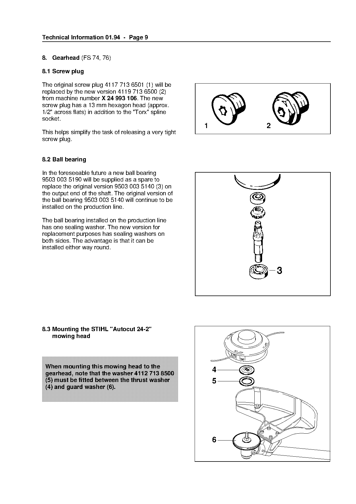
| 4117 713 6501 | 4119 713 6500 | The original screw plug 4117 713 6501 (1) will be replaced by the new version 4119 713 6500 (2) from machine number X 24 993 106. |
| 4126 791 7610 | 4126 791 7611 | 4 mm (1") and 26 mm (11/16"), the version 4126 791 7610 will be replaced by modified version 4126 791 7611. |
Full text
Page 1 of 12
Text of page 1 — search, copy, screen readers
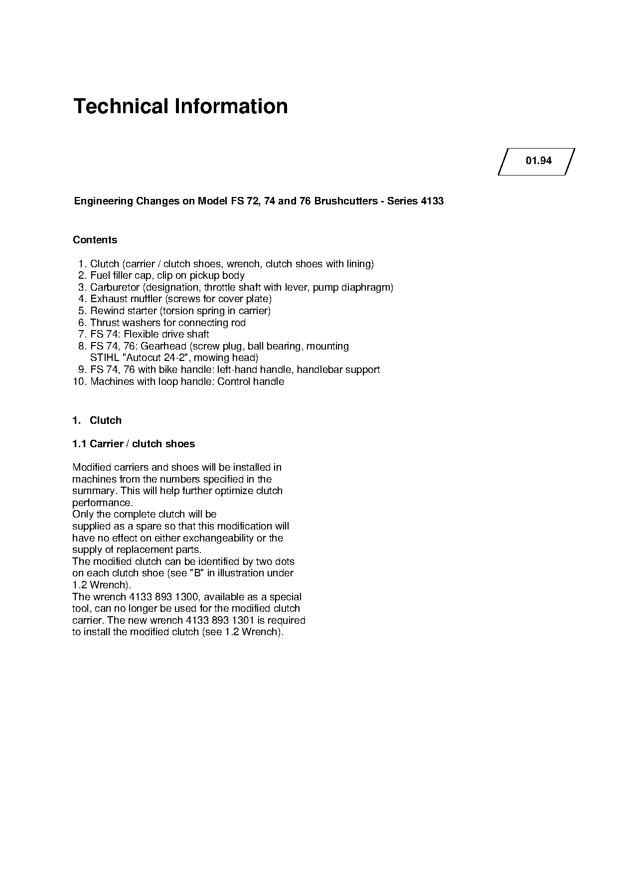
Technical Information

                                                                                 01.94

Engineering Changes on Model FS 72, 74 and 76 Brushcutters - Series 4133

Contents

 1. Clutch (carrier / clutch shoes, wrench, clutch shoes with lining)
 2. Fuel filler cap, clip on pickup body
 3. Carburetor (designation, throttle shaft with lever, pump diaphragm)

 4. Exhaust muffler (screws for cover plate)
 5. Rewind starter (torsion spring in carrier)
 6. Thrust washers for connecting rod

 7. FS 74: Flexible drive shaft
 8. FS 74, 76: Gearhead (screw plug, ball bearing, mounting
    STIHL "Autocut 24-2", mowing head)
 9. FS 74, 76 with bike handle: left-hand handle, handlebar support
10. Machines with loop handle: Control handle

1. Clutch

1.1 Carrier / clutch shoes

Modified carriers and shoes will be installed in

machines from the numbers specified in the
summary. This will help further optimize clutch

performance.
Only the complete clutch will be
supplied as a spare so that this modification will

have no effect on either exchangeability or the
supply of replacement parts.
The modified clutch can be identified by two dots

on each clutch shoe (see "B" in illustration under
1.2 Wrench).
The wrench 4133 893 1300, available as a special

tool, can no longer be used for the modified clutch
carrier. The new wrench 4133 893 1301 is required
to install the modified clutch (see 1.2 Wrench).
Page 2 of 12
Text of page 2 — search, copy, screen readers
Technical Information 01.94 - Page 2

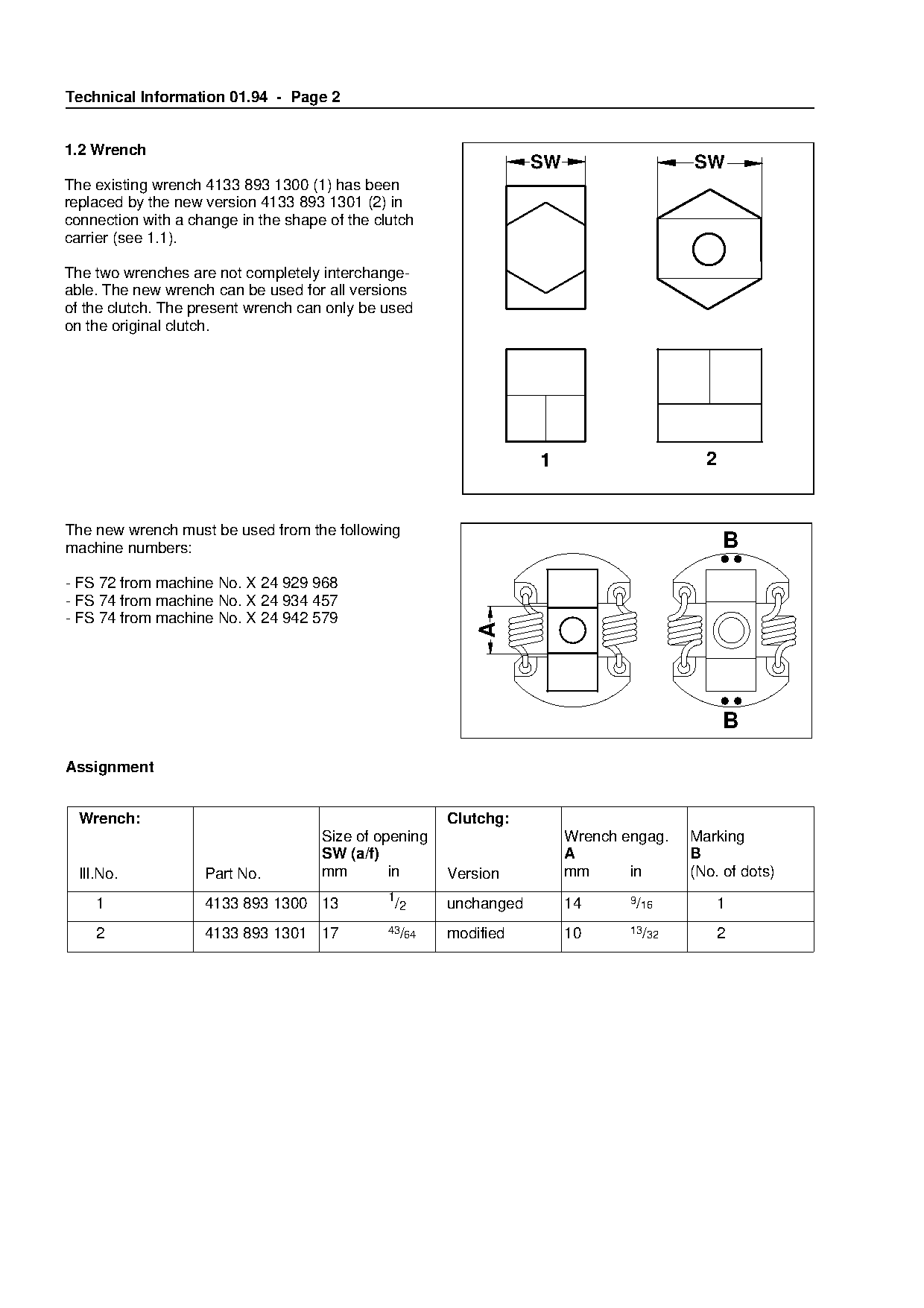
1.2 Wrench
                                                                   SW                   SW
The existing wrench 4133 893 1300 (1) has been
replaced by the new version 4133 893 1301 (2) in
connection with a change in the shape of the clutch
carrier (see 1.1).

The two wrenches are not completely interchange-
able. The new wrench can be used for all versions
of the clutch. The present wrench can only be used
on the original clutch.

                                                                   1                      2

The new wrench must be used from the following
machine numbers:                                                  fo                          B
- FS 72 from machine No. X 24 929 968
- FS 74 from machine No. X 24 934 457
- FS 74 from machine No. X 24 942 579
                                                           A


Assignment

  Wrench:                                              Clutchg:
                                     Size of opening                    Wrench engag.   Marking

                                     SW (a/f)                           A               B
  Ill.No.           Part No.         mm        in      Version          mm      in      (No. of dots)
                                               1                                9/16
     1              4133 893 1300 13            /2     unchanged        14                  1

     2              4133 893 1301 17           43/64   modified         10      13/32       2
Page 3 of 12
Text of page 3 — search, copy, screen readers
Technical Information 01.94 - Page 3

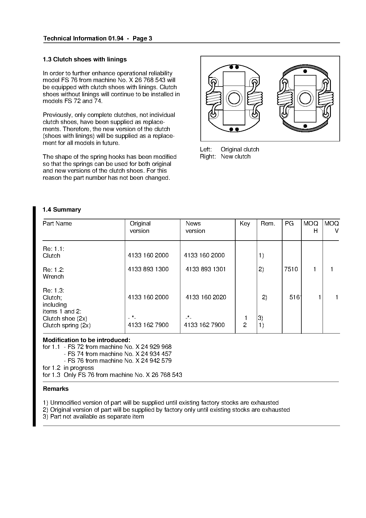
1.3 Clutch shoes with linings

In order to further enhance operational reliability
model FS 76 from machine No. X 26 768 543 will
be equipped with clutch shoes with linings. Clutch
shoes without linings will continue to be installed in
models FS 72 and 74.

Previously, only complete clutches, not individual
clutch shoes, have been supplied as replace-
ments. Therefore, the new version of the clutch
(shoes with linings) will be supplied as a replace-
ment for all models in future.

                                                              Left: Original clutch

The shape of the spring hooks has been modified               Right: New clutch
so that the springs can be used for both original
and new versions of the clutch shoes. For this

reason the part number has not been changed.

1.4 Summary

Part Name                         Original               News
                                                               fo           Key       Rem.    PG      MOQ       MOQ
                                  version                version                                        H         V

Re: 1.1:

Clutch                           4133 160 2000           4133 160 2000             1)

Re: 1.2:                         4133 893 1300           4133 893 1301             2)        7510      1         1
Wrench

Re: 1.3:

Clutch;                          4133 160 2000           4133 160 2020                2)       5161         1        1
including
items 1 and 2:

Clutch shoe (2x)                 - *-                    -*-                 1     3)
Clutch spring (2x)               4133 162 7900           4133 162 7900       2     1)

Modification to be introduced:
for 1.1 - FS 72 from machine No. X 24 929 968
        - FS 74 from machine No. X 24 934 457

        - FS 76 from machine No. X 24 942 579
for 1.2 in progress
for 1.3 Only FS 76 from machine No. X 26 768 543

Remarks

1) Unmodified version of part will be supplied until existing factory stocks are exhausted
2) Original version of part will be supplied by factory only until existing stocks are exhausted
3) Part not available as separate item
Page 4 of 12
Text of page 4 — search, copy, screen readers
Technical Information 01.94 - Page 4

2. Fuel filler cap, clip on pickup body

2.1 Fuel filler cap

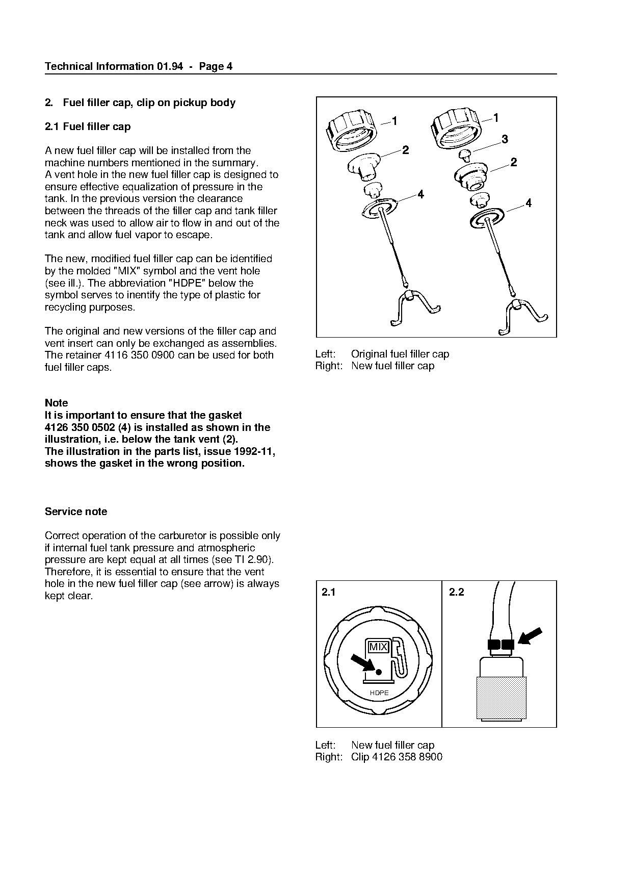
A new fuel filler cap will be installed from the
machine numbers mentioned in the summary.
A vent hole in the new fuel filler cap is designed to
ensure effective equalization of pressure in the
tank. In the previous version the clearance
between the threads of the filler cap and tank filler
neck was used to allow air to flow in and out of the
tank and allow fuel vapor to escape.

The new, modified fuel filler cap can be identified

by the molded "MIX" symbol and the vent hole
(see ill.). The abbreviation "HDPE" below the
symbol serves to inentify the type of plastic for

recycling purposes.

The original and new versions of the filler cap and

vent insert can only be exchanged as assemblies.
The retainer 4116 350 0900 can be used for both           Left: Original fuel filler cap
fuel filler caps.                                         Right: New fuel filler cap
Note
It is important to ensure that the gasket
4126 350 0502 (4) is installed as shown in the

illustration, i.e. below the tank vent (2).
The illustration in the parts list, issue 1992-11,
shows the gasket in the wrong position.

Service note

Correct operation of the carburetor is possible only
if internal fuel tank pressure and atmospheric

pressure are kept equal at all times (see TI 2.90).
Therefore, it is essential to ensure that the vent

hole in the new fuel filler cap (see arrow) is always
kept clear.                                                2.1                         2.2

                                                                      MIX

                                                                      HDPE

                                                          Left: New fuel filler cap
                                                          Right: Clip 4126 358 8900
Page 5 of 12
Text of page 5 — search, copy, screen readers
Technical Information 01.94 - Page 5

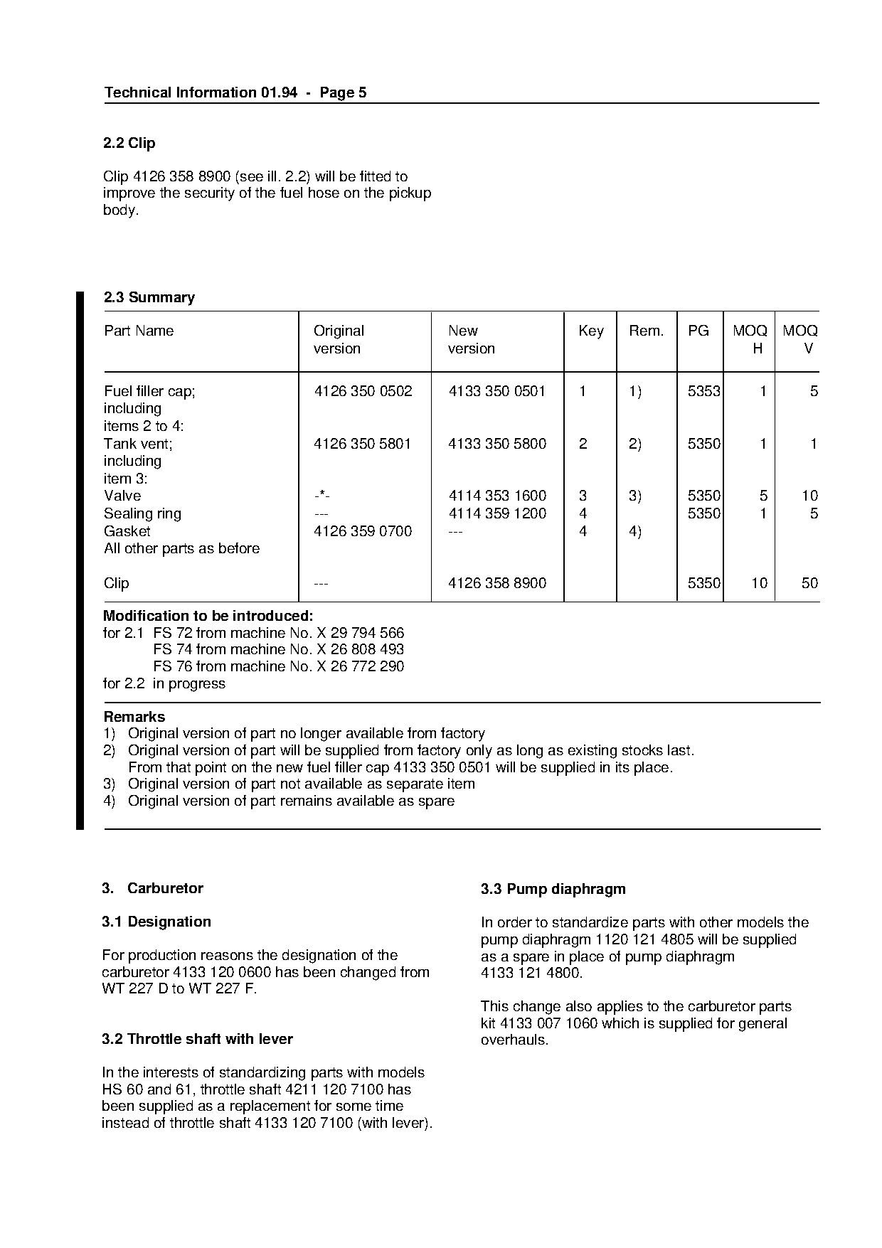
2.2 Clip

Clip 4126 358 8900 (see ill. 2.2) will be fitted to
improve the security of the fuel hose on the pickup
body.

2.3 Summary

Part Name                        Original               New                 Key     Rem.     PG     MOQ    MOQ
                                 version                version                                       H      V

Fuel filler cap;                 4126 350 0502          4133 350 0501       1       1)       5353      1          5
including

items 2 to 4:
Tank vent;                       4126 350 5801          4133 350 5800       2       2)       5350      1          1
including

item 3:
Valve                            -*-                    4114 353 1600       3       3)       5350      5       10
Sealing ring                     ---                    4114 359 1200       4                5350      1        5
Gasket
All other parts as before
                                 4126 359 0700          ---   fo            4       4)
Clip                             ---                    4126 358 8900                        5350     10       50

Modification to be introduced:
for 2.1 FS 72 from machine No. X 29 794 566
        FS 74 from machine No. X 26 808 493
        FS 76 from machine No. X 26 772 290

for 2.2 in progress

Remarks
1) Original version of part no longer available from factory
2) Original version of part will be supplied from factory only as long as existing stocks last.

   From that point on the new fuel filler cap 4133 350 0501 will be supplied in its place.
3) Original version of part not available as separate item
4) Original version of part remains available as spare

3. Carburetor                                               3.3 Pump diaphragm

3.1 Designation                                             In order to standardize parts with other models the
                                                            pump diaphragm 1120 121 4805 will be supplied
For production reasons the designation of the               as a spare in place of pump diaphragm
carburetor 4133 120 0600 has been changed from              4133 121 4800.
WT 227 D to WT 227 F.
                                                            This change also applies to the carburetor parts
                                                            kit 4133 007 1060 which is supplied for general
3.2 Throttle shaft with lever                               overhauls.

In the interests of standardizing parts with models
HS 60 and 61, throttle shaft 4211 120 7100 has
been supplied as a replacement for some time
instead of throttle shaft 4133 120 7100 (with lever).
Page 6 of 12
Text of page 6 — search, copy, screen readers
Technical Information 01.94 - Page 6

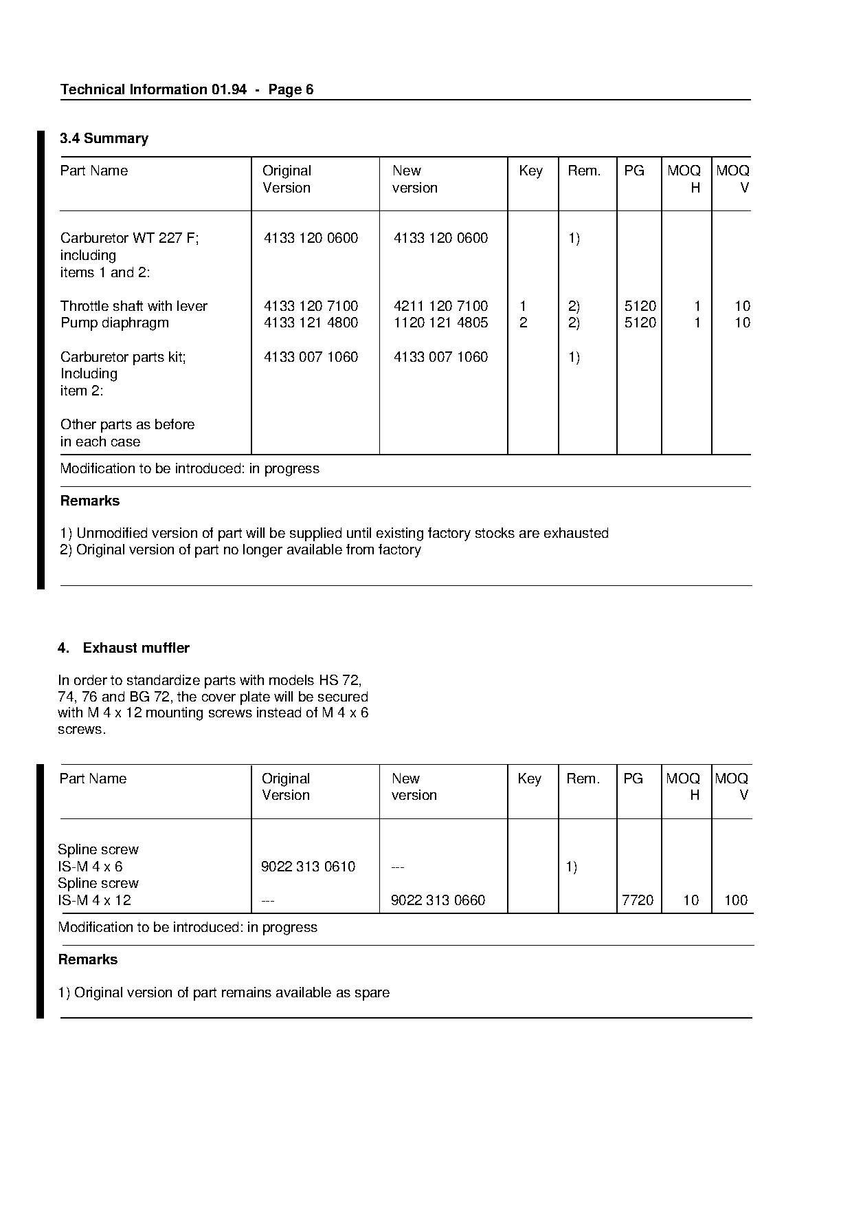
3.4 Summary

Part Name                        Original                New               Key     Rem.      PG     MOQ   MOQ
                                 Version                 version                                      H     V

Carburetor WT 227 F;             4133 120 0600           4133 120 0600             1)
including
items 1 and 2:

Throttle shaft with lever        4133 120 7100           4211 120 7100     1       2)        5120     1    10
Pump diaphragm                   4133 121 4800           1120 121 4805     2       2)        5120     1    10

Carburetor parts kit;            4133 007 1060           4133 007 1060             1)
Including
item 2:

Other parts as before
in each case

Modification to be introduced: in progress

Remarks
1) Unmodified version of part will be supplied until existing factory stocks are exhausted
2) Original version of part no longer available from factory

4. Exhaust muffler

In order to standardize parts with models HS 72,
74, 76 and BG 72, the cover plate will be secured
with M 4 x 12 mounting screws instead of M 4 x 6
screws.

Part Name                        Original                New              Key     Rem.       PG     MOQ   MOQ

                                 Version                 version                                      H     V

Spline screw
IS-M 4 x 6                      9022 313 0610            ---                      1)
Spline screw

IS-M 4 x 12                     ---                      9022 313 0660                       7720    10   100
Modification to be introduced: in progress

Remarks

1) Original version of part remains available as spare
Page 7 of 12
Text of page 7 — search, copy, screen readers
Technical Information 01.94 - Page 7

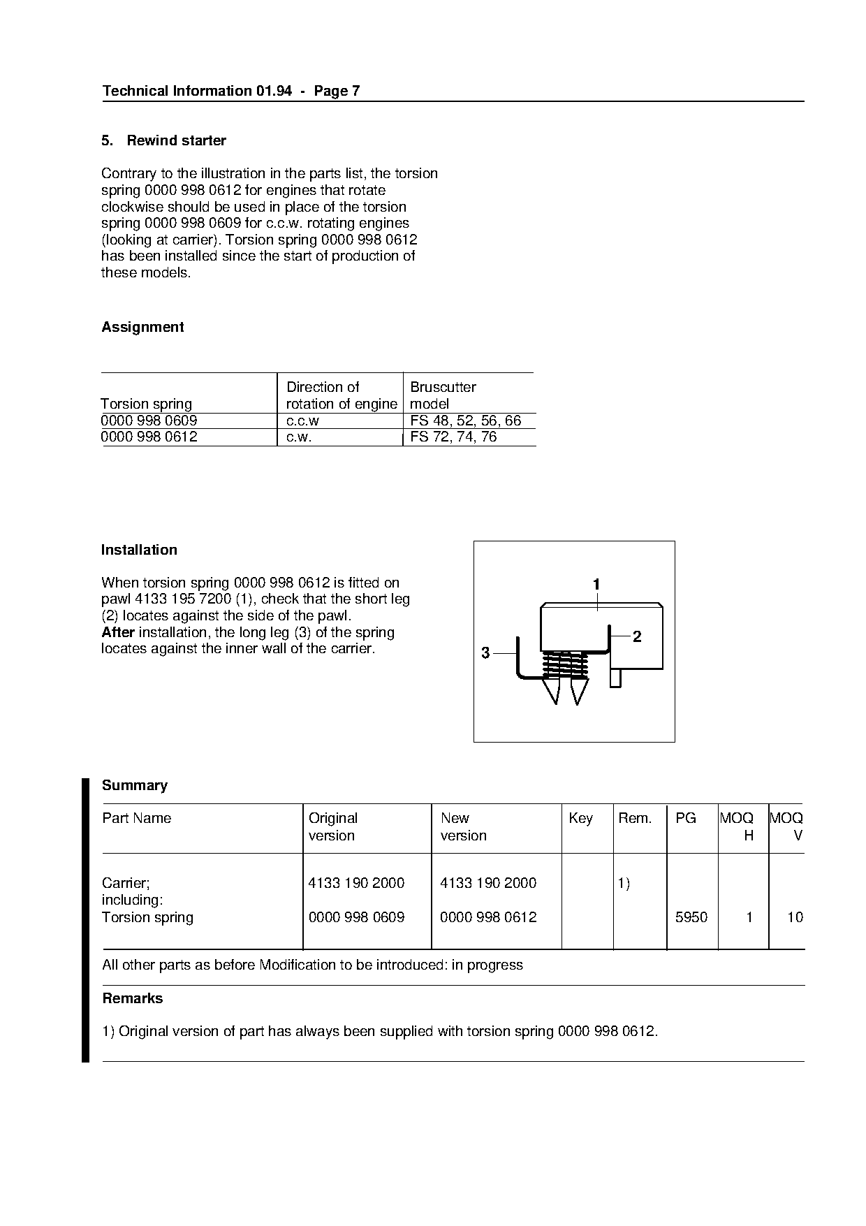
5. Rewind starter

Contrary to the illustration in the parts list, the torsion
spring 0000 998 0612 for engines that rotate
clockwise should be used in place of the torsion
spring 0000 998 0609 for c.c.w. rotating engines
(looking at carrier). Torsion spring 0000 998 0612
has been installed since the start of production of
these models.

Assignment

                                Direction of          Bruscutter
Torsion spring                  rotation of engine    model

0000 998 0609                   c.c.w                 FS 48, 52, 56, 66
0000 998 0612                   c.w.                  FS 72, 74, 76

Installation
When torsion spring 0000 998 0612 is fitted on                                  1
pawl 4133 195 7200 (1), check that the short leg

(2) locates against the side of the pawl.
After installation, the long leg (3) of the spring                                       2
locates against the inner wall of the carrier.                      3

Summary

Part Name                           Original                  New             Key   Rem.     PG     MOQ   MOQ
                                    version                   version                                 H     V

Carrier;                            4133 190 2000             4133 190 2000         1)
including:

Torsion spring                      0000 998 0609             0000 998 0612                  5950     1    10

All other parts as before Modification to be introduced: in progress

Remarks

1) Original version of part has always been supplied with torsion spring 0000 998 0612.
Page 8 of 12
Text of page 8 — search, copy, screen readers
Technical Information 01.94 - Page 8

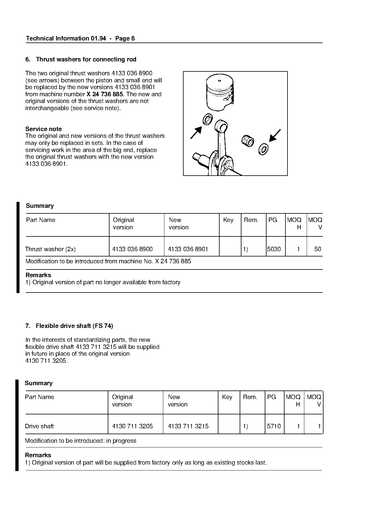
6. Thrust washers for connecting rod

The two original thrust washers 4133 036 8900
(see arrows) between the piston and small end will
be replaced by the new versions 4133 036 8901
from machine number X 24 736 885. The new and
original versions of the thrust washers are not
interchangeable (see service note).

Service note
The original and new versions of the thrust washers
may only be replaced in sets. In the case of

servicing work in the area of the big end, replace

the original thrust washers with the new version
4133 036 8901.

Summary

Part Name                         Original
                                  version
                                                        New
                                                        version
                                                                      fo     Key     Rem.         PG     MOQ
                                                                                                           H
                                                                                                               MOQ

Thrust washer (2x)                4133 036 8900         4133 036 8901                1)           5030     1    50

Modification to be introduced from machine No. X 24 736 885

Remarks

1) Original version of part no longer available from factory

7. Flexible drive shaft (FS 74)

In the interests of standardizing parts, the new
flexible drive shaft 4133 711 3215 will be supplied
in future in place of the original version

4130 711 3205.

Summary

Part Name                         Original              New                  Key     Rem.         PG     MOQ   MOQ
                                  version               version                                            H     V

Drive shaft                       4130 711 3205         4133 711 3215                1)           5710     1     1

Modification to be introduced: in progress

Rernarks
1) Original version of part will be supplied from factory only as long as existing stocks last.
Page 9 of 12
Text of page 9 — search, copy, screen readers
Technical Information 01.94 - Page 9

8. Gearhead (FS 74, 76)

8.1 Screw plug

The original screw plug 4117 713 6501 (1) will be
replaced by the new version 4119 713 6500 (2)
from machine number X 24 993 106. The new
screw plug has a 13 mm hexagon head (approx.
1/2" across flats) in addition to the "Torx" spline
socket.
                                                          1            2
This helps simplify the task of releasing a very tight
screw plug.

8.2 Ball bearing

In the foreseeable future a new ball bearing
9503 003 5190 will be supplied as a spare to
replace the original version 9503 003 5140 (3) on

the output end of the shaft. The original version of
the ball bearing 9503 003 5140 will continue to be
installed on the production line.

The ball bearing installed on the production line
has one sealing washer. The new version for
replacement purposes has sealing washers on
both sides. The advantage is that it can be

installed either way round.

8.3 Mounting the STIHL "Autocut 24-2"
    mowing head

 When mounting this mowing head to the
                                                              4

 gearhead, note that the washer 4112 713 8500
 (5) must be fitted between the thrust washer                 5
 (4) and guard washer (6).

                                                              6
Page 10 of 12
Text of page 10 — search, copy, screen readers
Technical Information 01.94 - Page 10

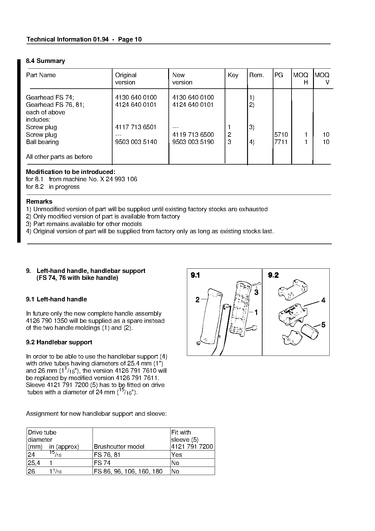
8.4 Summary

Part Name                          Original             New                  Key     Rem.         PG     MOQ   MOQ
                                   version              version                                            H     V

Gearhead FS 74;                    4130 640 0100        4130 640 0100                1)
Gearhead FS 76, 81;                4124 640 0101        4124 640 0101                2)
each of above
includes:
Screw plug                         4117 713 6501        ---                  1       3)
Screw plug                         ---                  4119 713 6500        2                    5710     1    10
Ball bearing                       9503 003 5140        9503 003 5190        3       4)           7711     1    10

All other parts as before

Modification to be introduced:

for 8.1 from machine No. X 24 993 106
for 8.2 in progress

Remarks
1) Unmodified version of part will be supplied until existing factory stocks are exhausted
2) Only modified version of part is available from factory
3) Part remains available for other models                            fo
4) Original version of part will be supplied from factory only as long as existing stocks last.

9. Left-hand handle, handlebar support
   (FS 74, 76 with bike handle)

9.1 Left-hand handle

In future only the new complete handle assembly
4126 790 1350 will be supplied as a spare instead

of the two handle moldings (1) and (2).

9.2 Handlebar support

In order to be able to use the handlebar support (4)
with drive tubes having diameters of 25.4 mm (1")
and 26 mm (11/16"), the version 4126 791 7610 will

be replaced by modified version 4126 791 7611.
Sleeve 4121 791 7200 (5) has to be fitted on drive
 tubes with a diameter of 24 mm (15/16").

Assignment for new handlebar support and sleeve:

Drive tube                                             Fit with
diameter                                               sleeve (5)
(mm) in (approx)            Brushcutter model          4121 791 7200
        15
24        /16               FS 76, 81                  Yes
25,4 1                      FS 74                      No
26      11/16               FS 86, 96, 106, 160, 180   No
Page 11 of 12
Text of page 11 — search, copy, screen readers
Technical Information 01.94 - Page 11

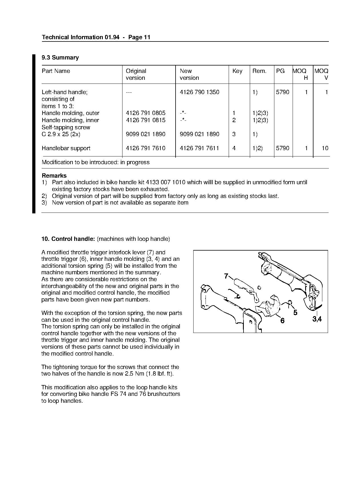
9.3 Summary

Part Name                         Original                 New             Key   Rem.     PG     MOQ      MOQ
                                  version                  version                                 H        V

Left-hand handle;                 ---                      4126 790 1350         1)       5790        1     1
consisting of
items 1 to 3:
Handle molding, outer             4126 791 0805            -*-             1     1)2)3)
Handle molding, inner             4126 791 0815            -*-             2     1)2)3)
Self-tapping screw
C 2.9 x 25 (2x)                   9099 021 1890            9099 021 1890   3     1)

Handlebar support                 4126 791 7610            4126 791 7611   4     1)2)     5790        1    10

Modification to be introduced: in progress

Remarks
1) Part also included in bike handle kit 4133 007 1010 which willl be supplied in unmodified form until

   existing factory stocks have been exhausted.
2) Original version of part will be supplied from factory only as long as existing stocks last.
3) New version of part is not available as separate item
10. Control handle: (machines with loop handle)

A modified throttle trigger interlock lever (7) and
throttle trigger (6), inner handle molding (3, 4) and an
additional torsion spring (5) will be installed from the

machine numbers mentioned in the summary.
As there are considerable restrictions on the

interchangeability of the new and original parts in the
original and modified control handle, the modified
parts have been given new part numbers.

With the exception of the torsion spring, the new parts
can be used in the original control handle.

The torsion spring can only be installed in the original
control handle together with the new versions of the
throttle trigger and inner handle molding. The original
versions of these parts cannot be used individually in

the modified control handle.

The tightening torque for the screws that connect the

two halves of the handle is now 2.5 Nm (1.8 lbf. ft).

This modification also applies to the loop handle kits
for converting bike handle FS 74 and 76 brushcutters
to loop handles.
Page 12 of 12
Text of page 12 — search, copy, screen readers
Technical Information 01.94 - Page 12

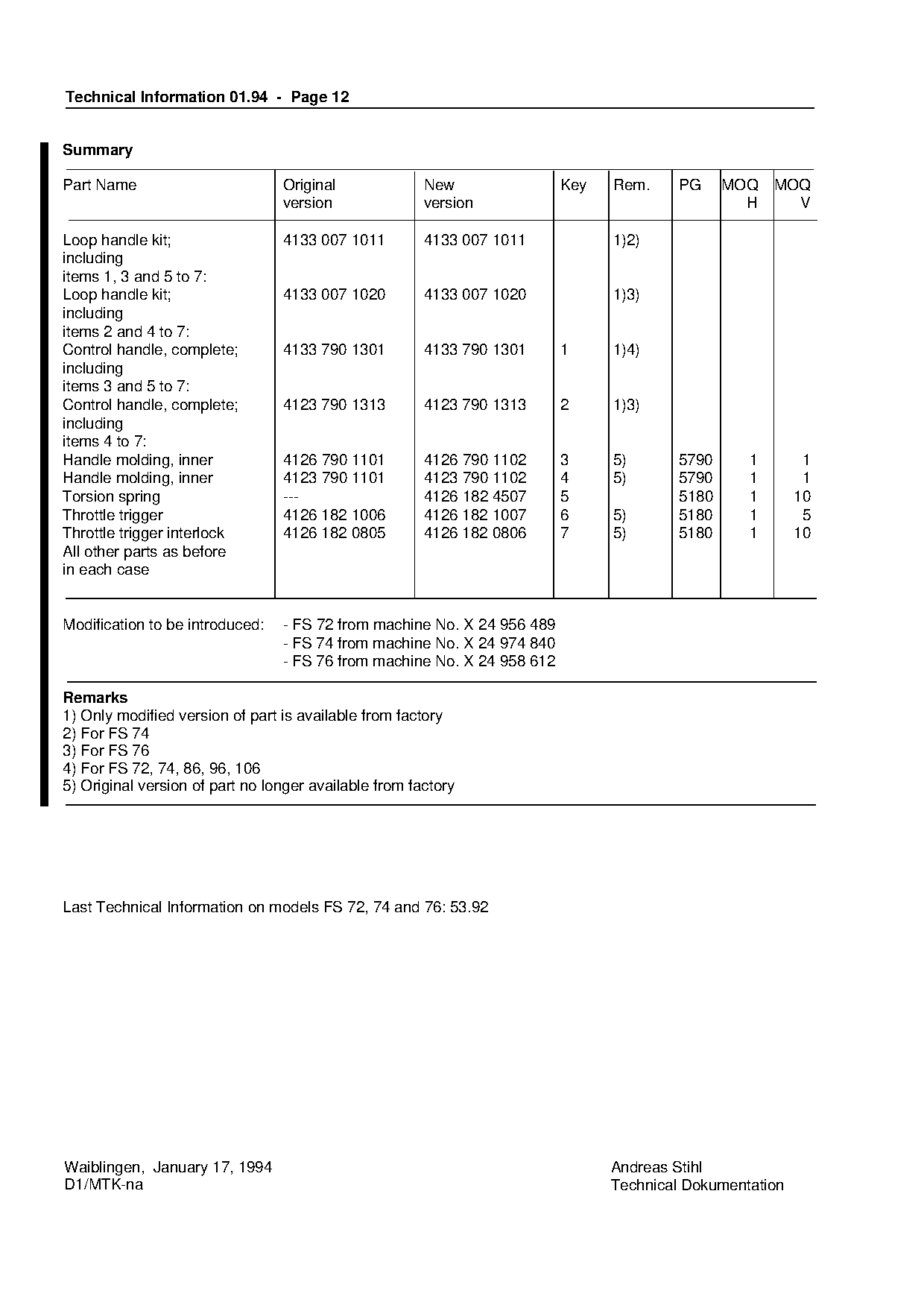
Summary

Part Name                        Original              New               Key   Rem.     PG    MOQ    MOQ
                                 version               version                                  H      V

Loop handle kit;                 4133 007 1011         4133 007 1011           1)2)
including
items 1, 3 and 5 to 7:
Loop handle kit;                 4133 007 1020         4133 007 1020           1)3)
including
items 2 and 4 to 7:
Control handle, complete;        4133 790 1301         4133 790 1301     1     1)4)

including

items 3 and 5 to 7:
Control handle, complete;        4123 790 1313         4123 790 1313     2     1)3)
including

items 4 to 7:
Handle molding, inner            4126 790 1101         4126 790 1102     3     5)      5790      1        1
Handle molding, inner            4123 790 1101         4123 790 1102     4     5)      5790      1        1

Torsion spring                   ---                   4126 182 4507     5             5180      1       10
Throttle trigger                 4126 182 1006         4126 182 1007     6     5)      5180      1        5
Throttle trigger interlock       4126 182 0805         4126 182 0806     7     5)      5180      1       10
All other parts as before
in each case

Modification to be introduced:   - FS 72 from machine No. X 24 956 489

                                 - FS 74 from machine No. X 24 974 840
                                 - FS 76 from machine No. X 24 958 612

Remarks

1) Only modified version of part is available from factory
2) For FS 74

3) For FS 76
4) For FS 72, 74, 86, 96, 106
5) Original version of part no longer available from factory

Last Technical Information on models FS 72, 74 and 76: 53.92

Waiblingen, January 17, 1994                                                   Andreas Stihl
D1/MTK-na                                                                      Technical Dokumentation
Most of these PDFs embed fonts with a shifted character map, so the text above was recovered rather than copied — read it as a faithful but imperfect transcription, and treat the page image above each block as the authority where the two disagree — the figures exist only there, because they are vector drawings that text extraction cannot keep.