Technical Information · issue 5 of 1994
Crankcase/shroud, clutch, wrench, deflector/gearhe
Model FC 72 Edger - Series 4133
IssueTI 5/1994
From serial 24 849 657, 24 957 772
Part changes (2)
| Was | Becomes | What the bulletin says |
|---|---|---|
| 4133 893 1300 | 4133 893 1301 | The existing wrench 4133 893 1300 (3) has been replaced by the new version 4133 893 1301 (4) in SW connection with the change in the shape of the SW clutch carrier (see 2. |
| 9503 003 6440 | 9503 003 6420 | The ball bearing 9503 003 6440 (11) on the output shaft will be replaced by the new version 9503 003 6420. |
Full text
Page 1 of 12
Text of page 1 — search, copy, screen readers
Technical Information

                                                                                             05.94

Model FC 72 Edger - Series 4133

Contents

1. Crankcase / shroud (new shape)
2. Clutch (carrier, wrench, clutch shoes, springs)
3. Deflector / gearhead (adjustment travel stop, depth wheel mounting, blade mounting,

   screw plug, ball bearing)
4. Exhaust muffler / cover plate (asymmetric hole pattern, mounting screws)
5. Fuel filler cap

6. Fuel pickup body (universal pickup body / clip deleted)
7. Control handle
8. Rewind starter (torsion spring in carrier)
9. Combination wrench                                    fo
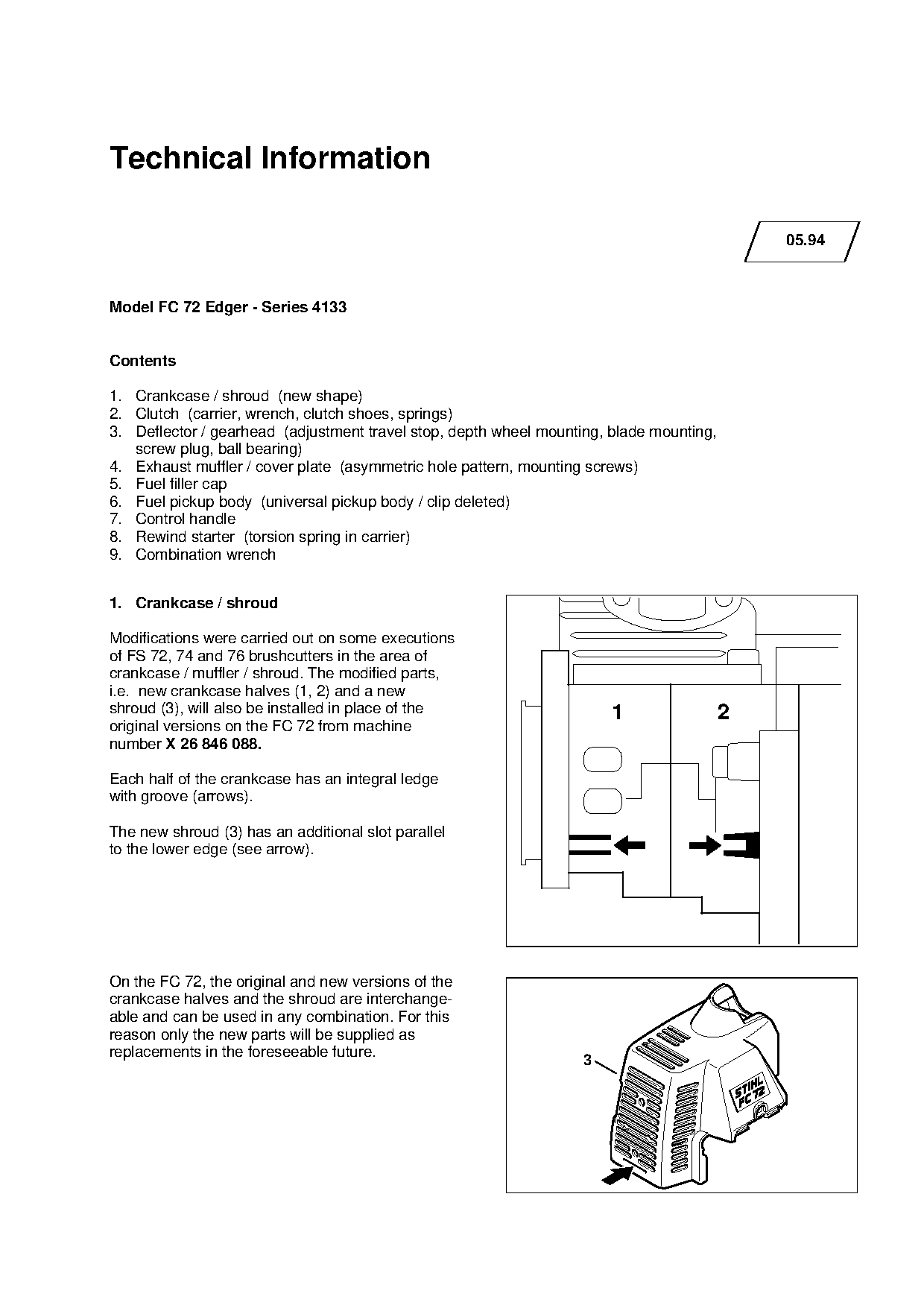
1. Crankcase / shroud

Modifications were carried out on some executions

of FS 72, 74 and 76 brushcutters in the area of
crankcase / muffler / shroud. The modified parts,
i.e. new crankcase halves (1, 2) and a new

shroud (3), will also be installed in place of the                     1                 2
original versions on the FC 72 from machine

number X 26 846 088.

Each half of the crankcase has an integral ledge
with groove (arrows).

The new shroud (3) has an additional slot parallel

to the lower edge (see arrow).

On the FC 72, the original and new versions of the
crankcase halves and the shroud are interchange-
able and can be used in any combination. For this
reason only the new parts will be supplied as
replacements in the foreseeable future.
                                                                   3
Page 2 of 12
Text of page 2 — search, copy, screen readers
Technical Information 05.94 - Page 2

Summary

Part Name                                          Original            New                Key      Rem.         MOQ
                                                   version             version                                    H
Crankcase (fan side)                               4133 020 2600       4133 020 2601       1           1)         1
Crankcase (starter side)                           4133 020 2800       4133 020 2801       2           1)         1
Shroud                                             4133 084 0900       4133 084 0901       3           1)         1

Modification to be introduced from machine number X 26 846 088

Remarks

1) Original version of part will be supplied by factory only until existing stocks are exhausted

2. Clutch

2.1 Carrier / clutch shoes

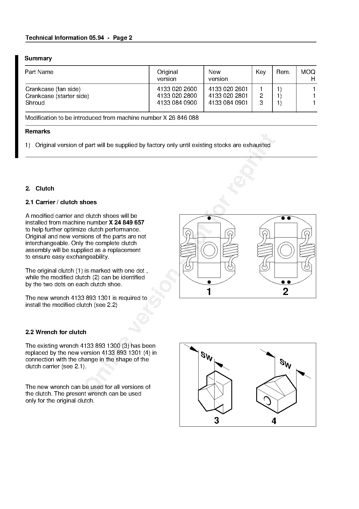
A modified carrier and clutch shoes will be
installed from machine number X 24 849 657
to help further optimize clutch performance.
Original and new versions of the parts are not
interchangeable. Only the complete clutch

assembly will be supplied as a replacement
to ensure easy exchangeability.

The original clutch (1) is marked with one dot ,

while the modified clutch (2) can be identified
by the two dots on each clutch shoe.

The new wrench 4133 893 1301 is required to
                                                                      1                                     2
install the modified clutch (see 2.2)

2.2 Wrench for clutch

The existing wrench 4133 893 1300 (3) has been
replaced by the new version 4133 893 1301 (4) in                    SW

connection with the change in the shape of the                                                          SW
clutch carrier (see 2.1).

The new wrench can be used for all versions of
the clutch. The present wrench can be used
only for the original clutch.

                                                                          3                        4
Page 3 of 12
Text of page 3 — search, copy, screen readers
Technical Information 05.94 - Page 3

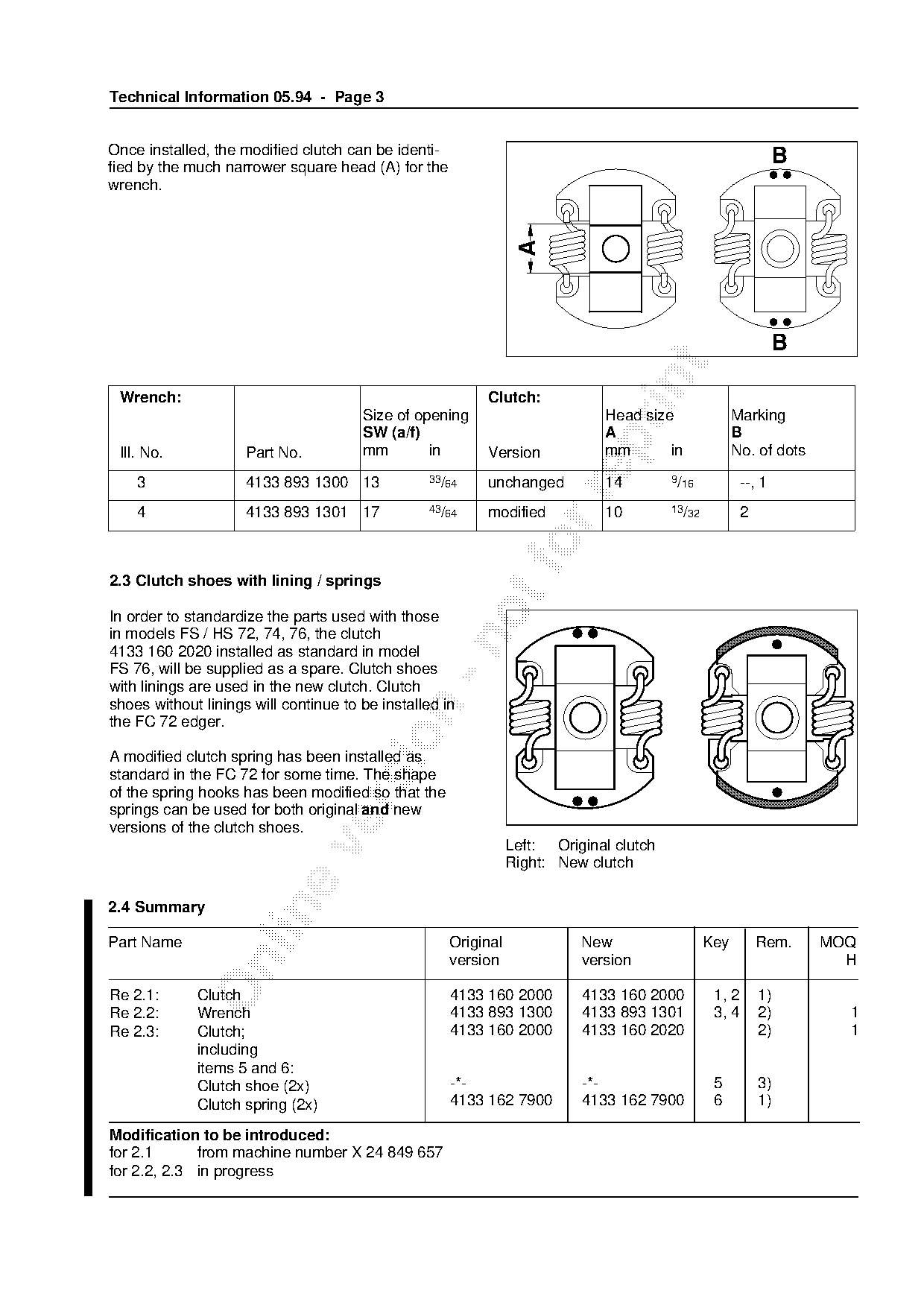
Once installed, the modified clutch can be identi-
fied by the much narrower square head (A) for the
                                                                                                                B
wrench.

                                                                 A
                                                                                                                B

 Wrench:                                                  Clutch:
                                       Size of opening                       Head size                Marking
                                       SW (a/f)                              A                        B

 Ill. No.            Part No.          mm        in       Version            mm       in              No. of dots

    3                4133 893 1300 13            33/64    unchanged          14         9/16            --, 1

    4                4133 893 1301 17            43/64    modified           10         13/32           2

2.3 Clutch shoes with lining / springs
In order to standardize the parts used with those
in models FS / HS 72, 74, 76, the clutch

4133 160 2020 installed as standard in model
FS 76, will be supplied as a spare. Clutch shoes
with linings are used in the new clutch. Clutch
shoes without linings will continue to be installed in

the FC 72 edger.

A modified clutch spring has been installed as
standard in the FC 72 for some time. The shape
of the spring hooks has been modified so that the

springs can be used for both original and new
versions of the clutch shoes.
                                                                Left: Original clutch

                                                                Right: New clutch

2.4 Summary

Part Name                                            Original             New                   Key         Rem.    MOQ
                                                     version              version                                     H

Re 2.1:      Clutch                                  4133 160 2000        4133 160 2000          1, 2       1)
Re 2.2:      Wrench                                  4133 893 1300        4133 893 1301          3, 4       2)        1
Re 2.3:      Clutch;                                 4133 160 2000        4133 160 2020                     2)        1
             including
             items 5 and 6:
             Clutch shoe (2x)                        -*-                  -*-                    5          3)
             Clutch spring (2x)                      4133 162 7900        4133 162 7900          6          1)

Modification to be introduced:
for 2.1      from machine number X 24 849 657
for 2.2, 2.3 in progress
Page 4 of 12
Text of page 4 — search, copy, screen readers
Technical Information 05.94 - Page 4

Remarks

1) Unmodified version of part will be supplied until existing factory stocks are exhausted
2) Original version of part will be supplied from factory only as long as existing stocks last
3) Part is not available as separate item

3. Deflector / gearhead

3.1 Adjustment travel stop for depth of cut

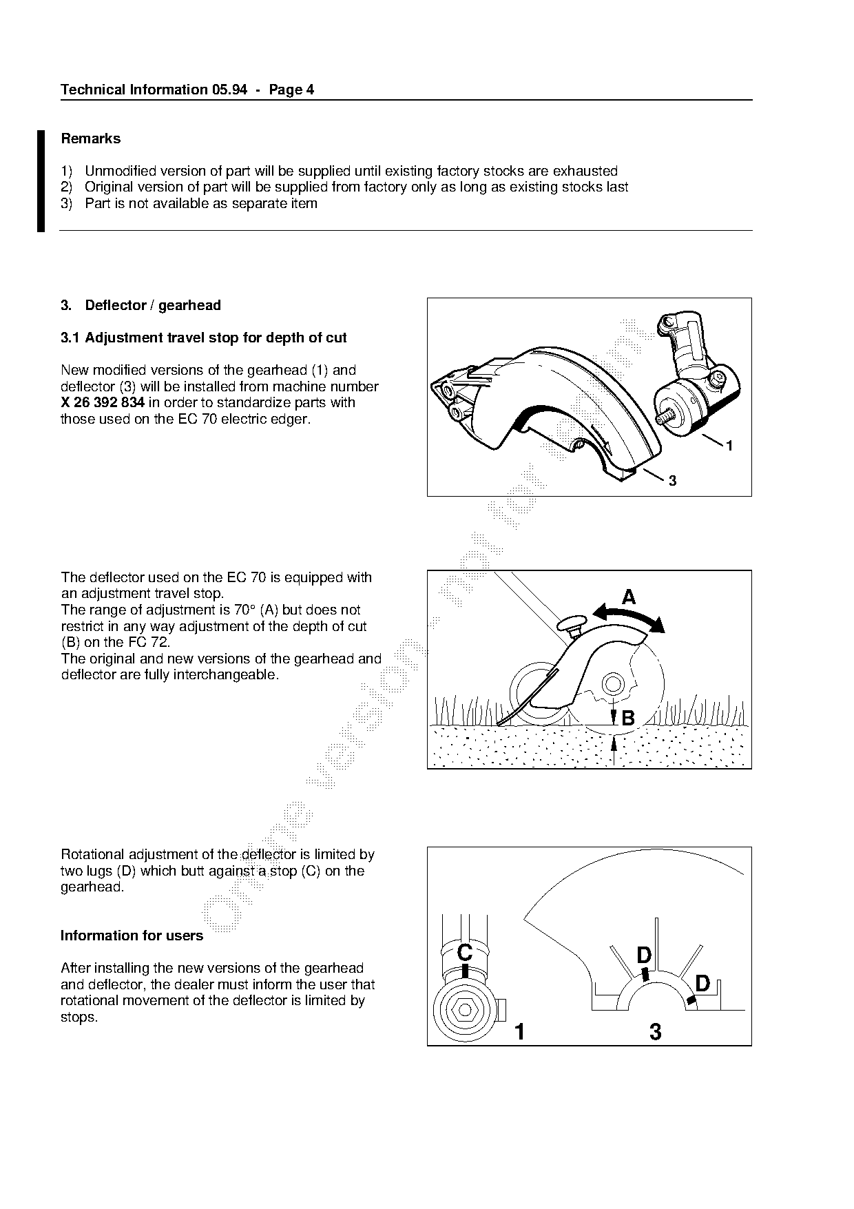
New modified versions of the gearhead (1) and
deflector (3) will be installed from machine number
X 26 392 834 in order to standardize parts with

those used on the EC 70 electric edger.
                                                                                                             1


The deflector used on the EC 70 is equipped with

an adjustment travel stop.                                                                  A
The range of adjustment is 70° (A) but does not
restrict in any way adjustment of the depth of cut
(B) on the FC 72.

The original and new versions of the gearhead and
deflector are fully interchangeable.


Rotational adjustment of the deflector is limited by
two lugs (D) which butt against a stop (C) on the
gearhead.

Information for users
                                                                 C                               D
After installing the new versions of the gearhead
and deflector, the dealer must inform the user that                                                      D
rotational movement of the deflector is limited by
stops.
                                                                          1                      3
Page 5 of 12
Text of page 5 — search, copy, screen readers
Technical Information 05.94 - Page 5

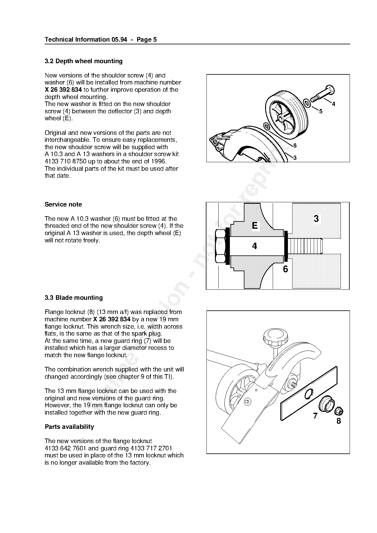
3.2 Depth wheel mounting

New versions of the shoulder screw (4) and
washer (6) will be installed from machine number
X 26 392 834 to further improve operation of the
depth wheel mounting.
The new washer is fitted on the new shoulder                                     4
screw (4) between the deflector (3) and depth                                5
wheel (E).

Original and new versions of the parts are not
interchangeable. To ensure easy replacements,
the new shoulder screw will be supplied with                         6

A 10.3 and A 13 washers in a shoulder screw kit

                                                                     3
4133 710 8750 up to about the end of 1996.
The individual parts of the kit must be used after
that date.

Service note

The new A 10.3 washer (6) must be fitted at the                          3
threaded end of the new shoulder screw (4). If the
original A 13 washer is used, the depth wheel (E)
                                                       fo    E
will not rotate freely.
                                                             4


3.3 Blade mounting

Flange locknut (8) (13 mm a/f) was replaced from
machine number X 26 392 834 by a new 19 mm
flange locknut. This wrench size, i.e. width across

flats, is the same as that of the spark plug.
At the same time, a new guard ring (7) will be

installed which has a larger diameter recess to
match the new flange locknut.

The combination wrench supplied with the unit will

changed accordingly (see chapter 9 of this TI).

The 13 mm flange locknut can be used with the

original and new versions of the guard ring.
However, the 19 mm flange locknut can only be
installed together with the new guard ring.
                                                                         7
                                                                                     8
Parts availability

The new versions of the flange locknut
4133 642 7601 and guard ring 4133 717 2701
must be used in place of the 13 mm locknut which
is no longer available from the factory.
Page 6 of 12
Text of page 6 — search, copy, screen readers
Technical Information 05.94 - Page 6

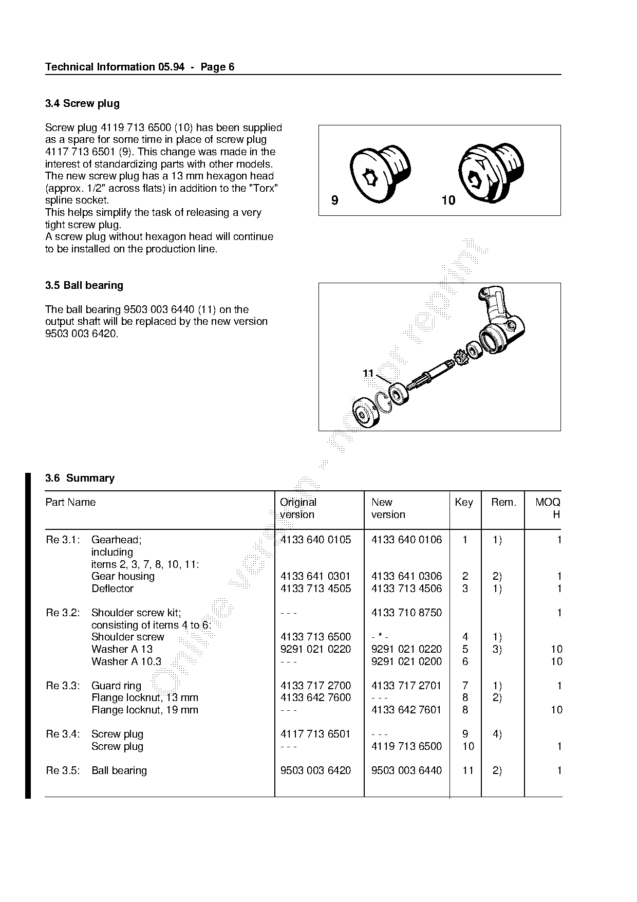
3.4 Screw plug

Screw plug 4119 713 6500 (10) has been supplied
as a spare for some time in place of screw plug
4117 713 6501 (9). This change was made in the
interest of standardizing parts with other models.
The new screw plug has a 13 mm hexagon head
(approx. 1/2" across flats) in addition to the "Torx"
spline socket.                                                 9                 10
This helps simplify the task of releasing a very
tight screw plug.
A screw plug without hexagon head will continue
to be installed on the production line.

3.5 Ball bearing

The ball bearing 9503 003 6440 (11) on the
output shaft will be replaced by the new version
9503 003 6420.


3.6 Summary

Part Name                                           Original         New             Key   Rem.   MOQ

                                                    version          version                        H

Re 3.1:   Gearhead;                                 4133 640 0105    4133 640 0106    1    1)       1
          including

          items 2, 3, 7, 8, 10, 11:
          Gear housing                              4133 641 0301    4133 641 0306    2    2)       1

          Deflector                                 4133 713 4505    4133 713 4506    3    1)       1

Re 3.2:   Shoulder screw kit;                       ---              4133 710 8750                  1
          consisting of items 4 to 6:

          Shoulder screw                            4133 713 6500    -*-              4    1)
          Washer A 13                               9291 021 0220    9291 021 0220    5    3)      10
          Washer A 10.3                             ---              9291 021 0200    6            10

Re 3.3:   Guard ring                                4133 717 2700    4133 717 2701    7    1)       1
          Flange locknut, 13 mm                     4133 642 7600    ---              8    2)
          Flange locknut, 19 mm                     ---              4133 642 7601    8            10

Re 3.4:   Screw plug                                4117 713 6501    ---              9    4)
          Screw plug                                ---              4119 713 6500    10            1

Re 3.5:   Ball bearing                              9503 003 6420    9503 003 6440    11   2)       1
Page 7 of 12
Text of page 7 — search, copy, screen readers
Technical Information 05.94 - Page 7

Modification to be introduced:
for 3.1, 3.2, 3.3     from machine number X 26 392 834
for 3.4               in progress
for 3.5               since start of production

Remarks

1)   Original version of part will be supplied by factory only until existing stocks are exhausted
2)   Original version of part no longer available from factory
3)   Quantity reduced from 2 to 1
4)   Part remains available for other models

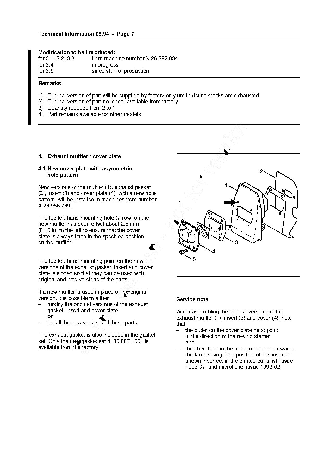
4. Exhaust muffler / cover plate

4.1 New cover plate with asymmetric
                                                                                                     2

    hole pattern

New versions of the muffler (1), exhaust gasket                                   1
(2), insert (3) and cover plate (4), with a new hole
pattern, will be installed in machines from number
X 26 985 789.
The top left-hand mounting hole (arrow) on the

new muffler has been offset about 2.5 mm
(0.10 in) to the left to ensure that the cover
plate is always fitted in the specified position
on the muffler.                                                                        3


The top left-hand mounting point on the new                         5
versions of the exhaust gasket, insert and cover
plate is slotted so that they can be used with
original and new versions of the parts.

If a new muffler is used in place of the original

version, it is possible to either                            Service note
– modify the original versions of the exhaust
     gasket, insert and cover plate                          When assembling the original versions of the
     or                                                      exhaust muffler (1), insert (3) and cover (4), note

– install the new versions of these parts.                   that
                                                             – the outlet on the cover plate must point
The exhaust gasket is also included in the gasket                 in the direction of the rewind starter

set. Only the new gasket set 4133 007 1051 is                     and
available from the factory.                                  – the short tube in the insert must point towards
                                                                  the fan housing. The position of this insert is
                                                                  shown incorrect in the printed parts list, issue
                                                                  1993-07, and microfiche, issue 1993-02.
Page 8 of 12
Text of page 8 — search, copy, screen readers
Technical Information 05.94 - Page 8

4.2 Mounting screws for cover plate

In order to standardize parts with models FS / HS
72, 74, 76 and BG 72, the cover plate will be
secured with M 4 x 12 mounting screws instead
of M 4 x 6 screws.

4.3 Summary

Part Name                                             Original              New                   Key   Rem.   MOQ
                                                      version               version                              H

Muffler                                               4133 140 0605          4133 140 0606         1    1)

Exhaust gasket                                        4133 149 0600          4133 149 0601         2    1)       1
Insert                                                4133 145 1000          4133 145 1001         3    1)       1
Cover plate                                           4133 145 0600          4133 145 0601         4    1)       5

Spline screw IS-M 4 x 6                               9022 313 0610          ---                   5    2)
Spline screw IS-M 4 x 12                              ---                    9022 313 0660         5            10

Gasket set;                                           4133 007 1050          4133 007 1051              3)       1
including item 2:

All other parts as before                                                fo
Modification to be introduced:
for 4.1: from machine number X 26 985 789
for 4.2: in progress

Remarks
1) Original version of part will be supplied by factory only until existing stocks are exhausted
2) Original version of part remains available as spare
3) Original version of part no longer available from factory

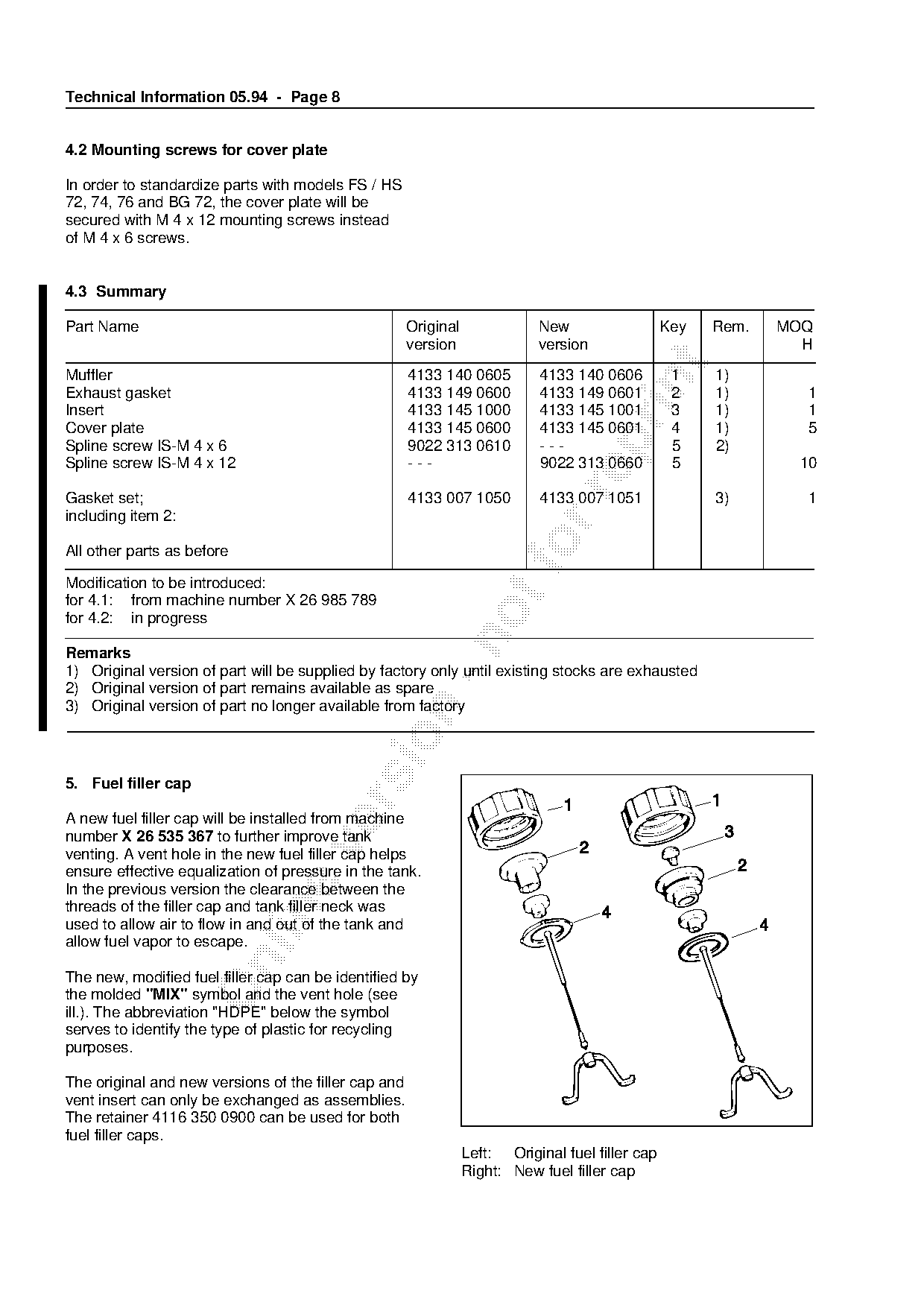
5. Fuel filler cap

A new fuel filler cap will be installed from machine
number X 26 535 367 to further improve tank

venting. A vent hole in the new fuel filler cap helps
ensure effective equalization of pressure in the tank.
In the previous version the clearance between the
threads of the filler cap and tank filler neck was

used to allow air to flow in and out of the tank and
allow fuel vapor to escape.

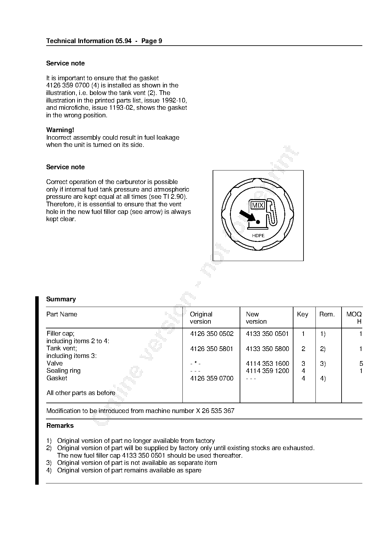
The new, modified fuel filler cap can be identified by
the molded "MIX" symbol and the vent hole (see
ill.). The abbreviation "HDPE" below the symbol
serves to identify the type of plastic for recycling
purposes.

The original and new versions of the filler cap and
vent insert can only be exchanged as assemblies.
The retainer 4116 350 0900 can be used for both
fuel filler caps.
                                                                 Left: Original fuel filler cap
                                                                 Right: New fuel filler cap
Page 9 of 12
Text of page 9 — search, copy, screen readers
Technical Information 05.94 - Page 9

Service note

It is important to ensure that the gasket
4126 359 0700 (4) is installed as shown in the
illustration, i.e. below the tank vent (2). The
illustration in the printed parts list, issue 1992-10,
and microfiche, issue 1193-02, shows the gasket
in the wrong position.

Warning!
Incorrect assembly could result in fuel leakage
when the unit is turned on its side.

Service note

Correct operation of the carburetor is possible

only if internal fuel tank pressure and atmospheric
pressure are kept equal at all times (see TI 2.90).
Therefore, it is essential to ensure that the vent                         MIX

hole in the new fuel filler cap (see arrow) is always
kept clear.

                                                                    fo     HDPE

Summary

Part Name                                                Original        New              Key       Rem.   MOQ
                                                         version         version                             H
Filler cap;                                              4126 350 0502   4133 350 0501      1       1)       1

including items 2 to 4:
Tank vent;                                               4126 350 5801   4133 350 5800      2       2)       1
including items 3:

Valve                                                    -*-             4114 353 1600      3       3)       5
Sealing ring                                             ---             4114 359 1200      4                1
Gasket                                                   4126 359 0700   ---                4       4)

All other parts as before

Modification to be introduced from machine number X 26 535 367

Remarks

1) Original version of part no longer available from factory
2) Original version of part will be supplied by factory only until existing stocks are exhausted.
   The new fuel filler cap 4133 350 0501 should be used thereafter.
3) Original version of part is not available as separate item
4) Original version of part remains available as spare
Page 10 of 12
Text of page 10 — search, copy, screen readers
Technical Information 05.94 - Page 10

6. Fuel pickup body

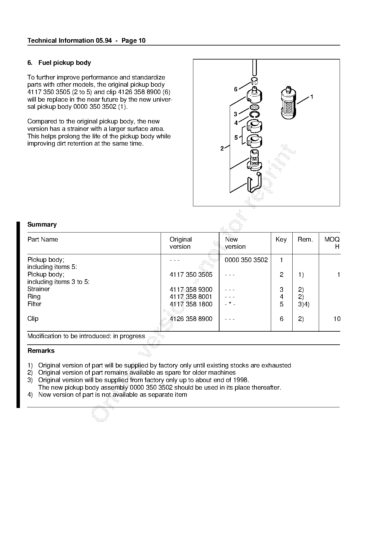
To further improve performance and standardize
parts with other models, the original pickup body
4117 350 3505 (2 to 5) and clip 4126 358 8900 (6)                            6
will be replace in the near future by the new univer-                                                     1
sal pickup body 0000 350 3502 (1).
                                                                            3
Compared to the original pickup body, the new                               4
version has a strainer with a larger surface area.
This helps prolong the life of the pickup body while                         5
improving dirt retention at the same time.
                                                                      2

Summary

Part Name                                          Original
                                                                    fo    New             Key      Rem.       MOQ
                                                   version                version                               H
Pickup body;                                       ---                    0000 350 3502    1
including items 5:

Pickup body;                                       4117 350 3505          ---              2       1)           1
including items 3 to 5:
Strainer                                           4117 358 9300          ---              3       2)

Ring                                               4117 358 8001          ---              4       2)
Filter                                             4117 358 1800          -*-              5       3)4)

Clip                                               4126 358 8900          ---              6       2)          10

Modification to be introduced: in progress

Remarks

1) Original version of part will be supplied by factory only until existing stocks are exhausted
2) Original version of part remains available as spare for older machines

3) Original version will be supplied from factory only up to about end of 1998.
   The new pickup body assembly 0000 350 3502 should be used in its place thereafter.
4) New version of part is not available as separate item
Page 11 of 12
Text of page 11 — search, copy, screen readers
Technical Information 05.94 - Page 11

7. Control handle

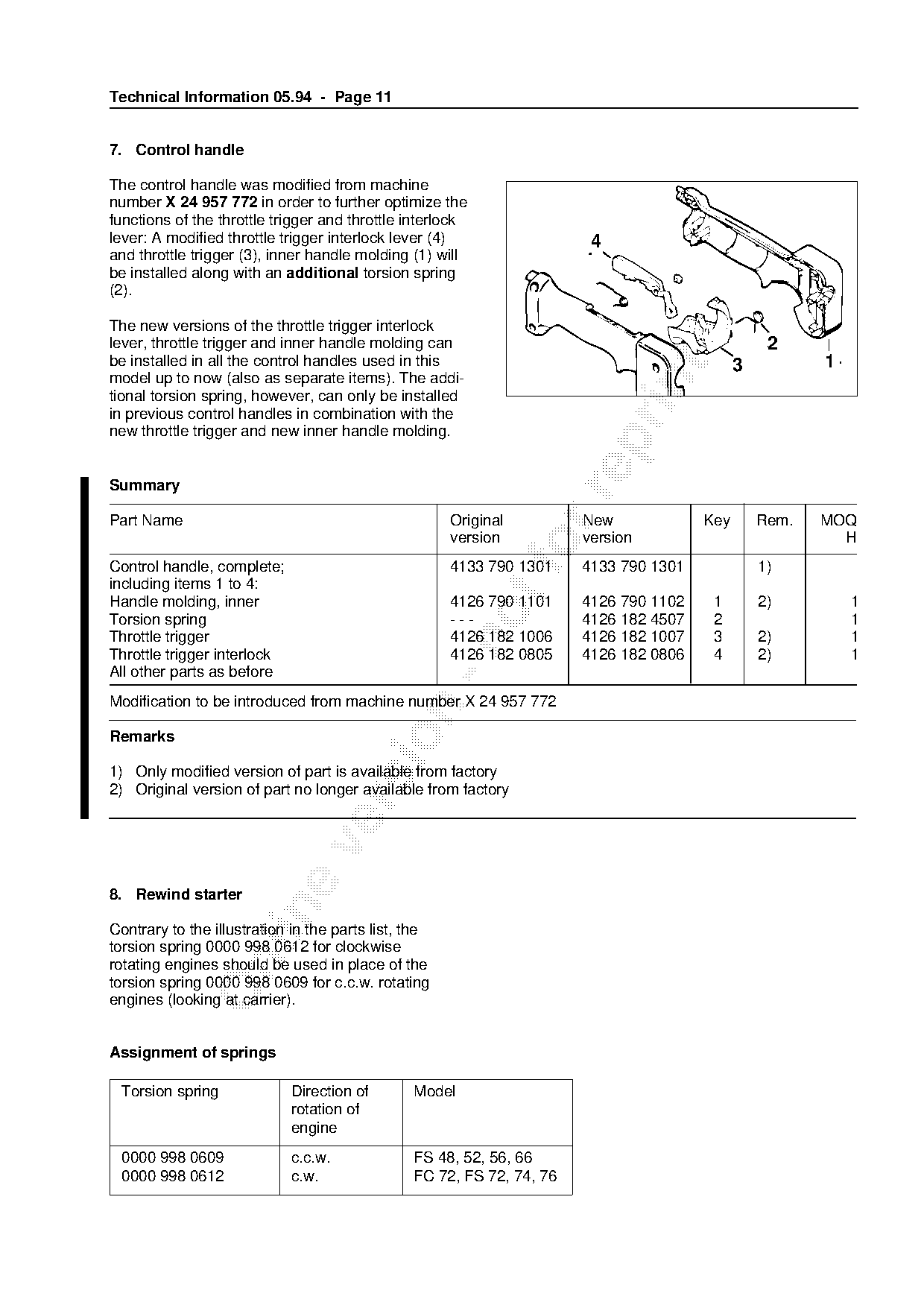
The control handle was modified from machine
number X 24 957 772 in order to further optimize the
functions of the throttle trigger and throttle interlock
lever: A modified throttle trigger interlock lever (4)                  4
and throttle trigger (3), inner handle molding (1) will
be installed along with an additional torsion spring
(2).

The new versions of the throttle trigger interlock
lever, throttle trigger and inner handle molding can                                              2
be installed in all the control handles used in this                                         3          1

model up to now (also as separate items). The addi-

tional torsion spring, however, can only be installed
in previous control handles in combination with the
new throttle trigger and new inner handle molding.

Summary

Part Name                                             Original         New             Key       Rem.   MOQ
                                                      version          version                            H
Control handle, complete;
                                                      4133 790 1301    4133 790 1301             1)
including items 1 to 4:
Handle molding, inner                                 4126 790 1101    4126 790 1102    1        2)         1
Torsion spring                                        ---              4126 182 4507    2                   1
Throttle trigger                                      4126 182 1006    4126 182 1007    3        2)         1

Throttle trigger interlock                            4126 182 0805    4126 182 0806    4        2)         1
All other parts as before
Modification to be introduced from machine number X 24 957 772

Remarks

1) Only modified version of part is available from factory
2) Original version of part no longer available from factory

8. Rewind starter

Contrary to the illustration in the parts list, the
torsion spring 0000 998 0612 for clockwise

rotating engines should be used in place of the
torsion spring 0000 998 0609 for c.c.w. rotating
engines (looking at carrier).

Assignment of springs

 Torsion spring              Direction of       Model
                             rotation of
                             engine
 0000 998 0609               c.c.w.             FS 48, 52, 56, 66
 0000 998 0612               c.w.               FC 72, FS 72, 74, 76
Page 12 of 12
Text of page 12 — search, copy, screen readers
Technical Information 05.94 - Page 12

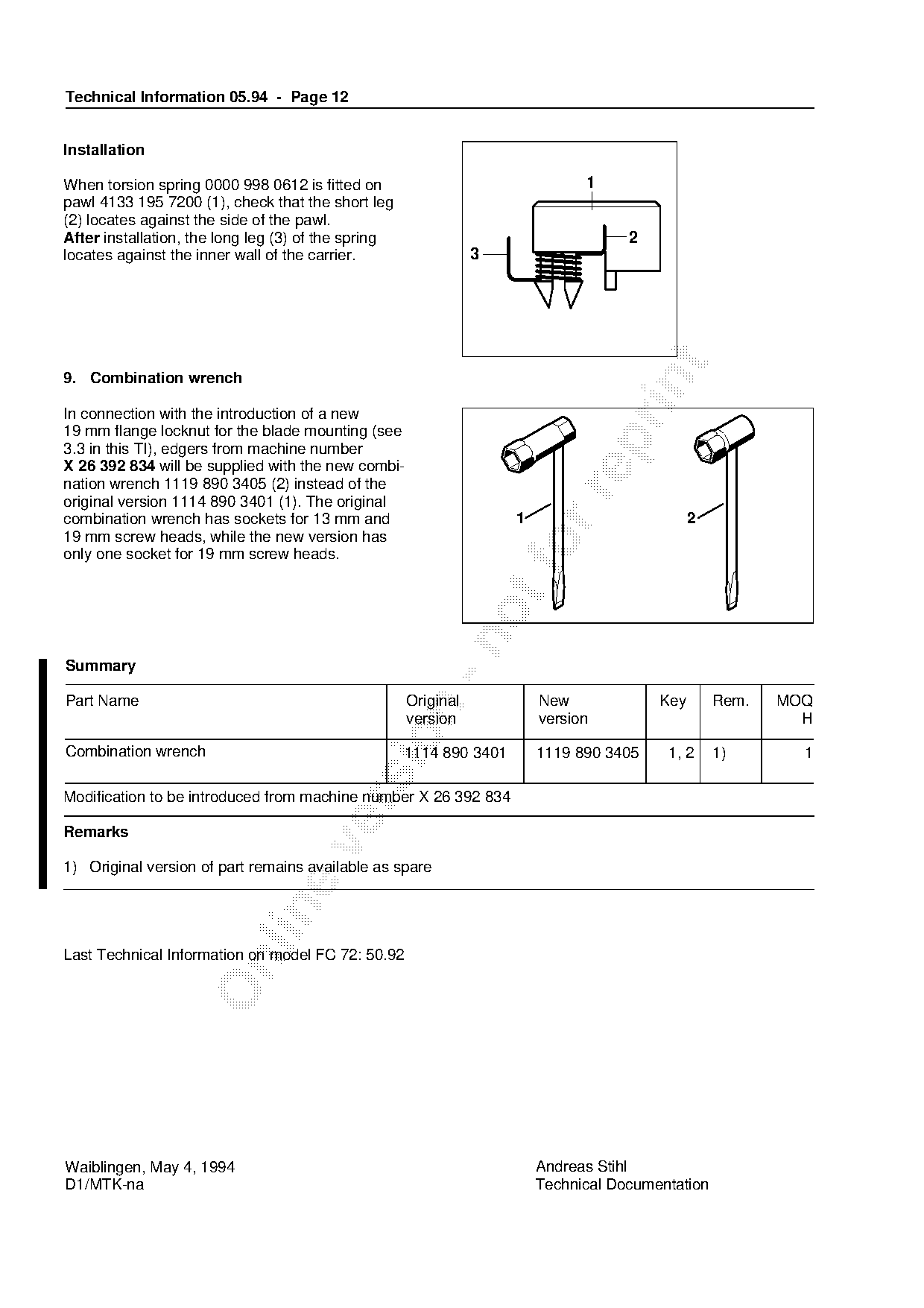
Installation

When torsion spring 0000 998 0612 is fitted on                                 1
pawl 4133 195 7200 (1), check that the short leg
(2) locates against the side of the pawl.
After installation, the long leg (3) of the spring                                   2
locates against the inner wall of the carrier.                  3

9. Combination wrench

In connection with the introduction of a new
19 mm flange locknut for the blade mounting (see

3.3 in this TI), edgers from machine number
X 26 392 834 will be supplied with the new combi-
nation wrench 1119 890 3405 (2) instead of the

original version 1114 890 3401 (1). The original
combination wrench has sockets for 13 mm and                         1                         2
19 mm screw heads, while the new version has
only one socket for 19 mm screw heads.                               fo

Summary

Part Name                                            Original            New             Key       Rem.   MOQ

                                                     version             version                            H

Combination wrench                                   1114 890 3401       1119 890 3405    1, 2     1)       1

Modification to be introduced from machine number X 26 392 834

Remarks

1) Original version of part remains available as spare

Last Technical Information on model FC 72: 50.92

Waiblingen, May 4, 1994                                                  Andreas Stihl
D1/MTK-na                                                                Technical Documentation
Most of these PDFs embed fonts with a shifted character map, so the text above was recovered rather than copied — read it as a faithful but imperfect transcription, and treat the page image above each block as the authority where the two disagree — the figures exist only there, because they are vector drawings that text extraction cannot keep.