Technical Information · issue 10 of 1994
Easy start system
Model 021, 023, 025 Chain Saws - Series 1123
Full text
Page 1 of 6
Text of page 1 — search, copy, screen readers
Technical Information

                                                                                                10.94

Model 021, 023, 025 Chain Saws - Series 1123
New versions with easy start system

                           3                             fo
                                                                     2
                                               1

Model 021, 023 and 025 chain saws are now               reduce the number of pulls required for starting by
available in a version with an easy start system        about 40%.
for users who attach special importance to starting     The decompression valve relieves the compressi-

behavior. The easy start system helps reduce the        on pressure in the combustion chamber during cran-
physical effort required to crank the engine and thus   king and helps reduce the effort needed to pull the
enhances operator comfort.                              starter rope. It is opened manually and closes auto-
                                                        matically as soon as the engine fires.
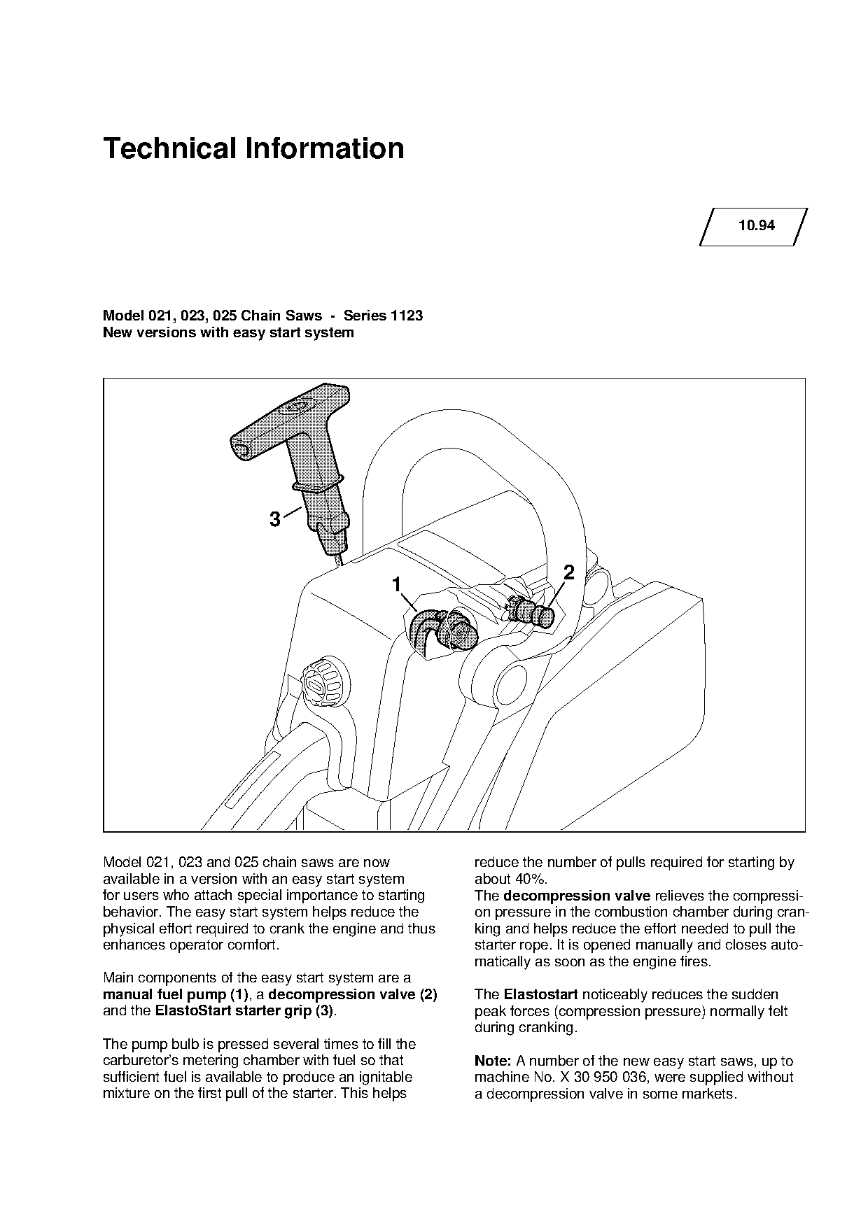
Main components of the easy start system are a
manual fuel pump (1), a decompression valve (2)         The Elastostart noticeably reduces the sudden
and the ElastoStart starter grip (3).                   peak forces (compression pressure) normally felt
                                                        during cranking.
The pump bulb is pressed several times to fill the
carburetor’s metering chamber with fuel so that         Note: A number of the new easy start saws, up to
sufficient fuel is available to produce an ignitable    machine No. X 30 950 036, were supplied without
mixture on the first pull of the starter. This helps    a decompression valve in some markets.
Page 2 of 6
Text of page 2 — search, copy, screen readers
Technical Information 10.94 - Page 2

1.   Construction and function

1.1 Fuel pump / carburetor

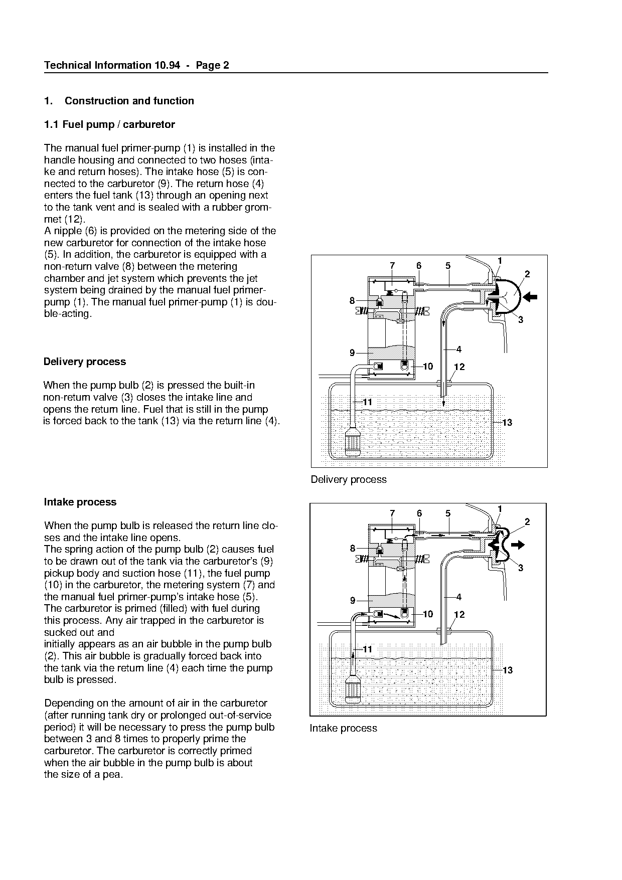
The manual fuel primer-pump (1) is installed in the
handle housing and connected to two hoses (inta-
ke and return hoses). The intake hose (5) is con-
nected to the carburetor (9). The return hose (4)
enters the fuel tank (13) through an opening next
to the tank vent and is sealed with a rubber grom-
met (12).
A nipple (6) is provided on the metering side of the
new carburetor for connection of the intake hose

(5). In addition, the carburetor is equipped with a

                                                                                                    1
non-return valve (8) between the metering                                     7   6        5
chamber and jet system which prevents the jet                                                                2
system being drained by the manual fuel primer-

pump (1). The manual fuel primer-pump (1) is dou-                  8
ble-acting.
                                                                                                         3

                                                                   9                           4
Delivery process

When the pump bulb (2) is pressed the built-in
                                                                  fo                  10       12

non-return valve (3) closes the intake line and
                                                                       11
opens the return line. Fuel that is still in the pump
is forced back to the tank (13) via the return line (4).                                            13

                                                           Delivery process

Intake process
                                                                                                    1
                                                                              7   6        5
When the pump bulb is released the return line clo-                                                          2
ses and the intake line opens.

The spring action of the pump bulb (2) causes fuel                 8
to be drawn out of the tank via the carburetor’s (9)
                                                                                                         3

pickup body and suction hose (11), the fuel pump
(10) in the carburetor, the metering system (7) and
the manual fuel primer-pump’s intake hose (5).                     9                           4
The carburetor is primed (filled) with fuel during

                                                                                      10       12
this process. Any air trapped in the carburetor is
sucked out and
initially appears as an air bubble in the pump bulb

                                                                       11
(2). This air bubble is gradually forced back into
the tank via the return line (4) each time the pump                                                 13
bulb is pressed.

Depending on the amount of air in the carburetor
(after running tank dry or prolonged out-of-service
period) it will be necessary to press the pump bulb        Intake process
between 3 and 8 times to properly prime the
carburetor. The carburetor is correctly primed
when the air bubble in the pump bulb is about
the size of a pea.
Page 3 of 6
Text of page 3 — search, copy, screen readers
Technical Information 10.94 - Page 3

1.2    Decompression valve

1.2.1 Construction

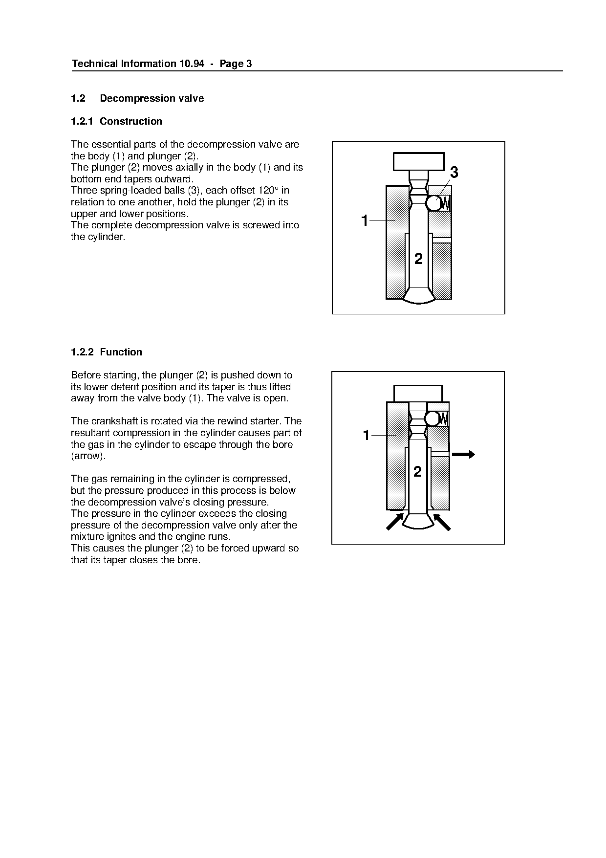
The essential parts of the decompression valve are
the body (1) and plunger (2).
The plunger (2) moves axially in the body (1) and its
bottom end tapers outward.                                             3
Three spring-loaded balls (3), each offset 120° in
relation to one another, hold the plunger (2) in its
upper and lower positions.
The complete decompression valve is screwed into              1
the cylinder.


1.2.2 Function

Before starting, the plunger (2) is pushed down to
its lower detent position and its taper is thus lifted
away from the valve body (1). The valve is open.

The crankshaft is rotated via the rewind starter. The
resultant compression in the cylinder causes part of          1
the gas in the cylinder to escape through the bore
(arrow).

The gas remaining in the cylinder is compressed,
                                                                   2

but the pressure produced in this process is below
the decompression valve’s closing pressure.
The pressure in the cylinder exceeds the closing
pressure of the decompression valve only after the

mixture ignites and the engine runs.
This causes the plunger (2) to be forced upward so

that its taper closes the bore.
Page 4 of 6
Text of page 4 — search, copy, screen readers
Technical Information 10.94 - Page 4

1.3 ElastoStart

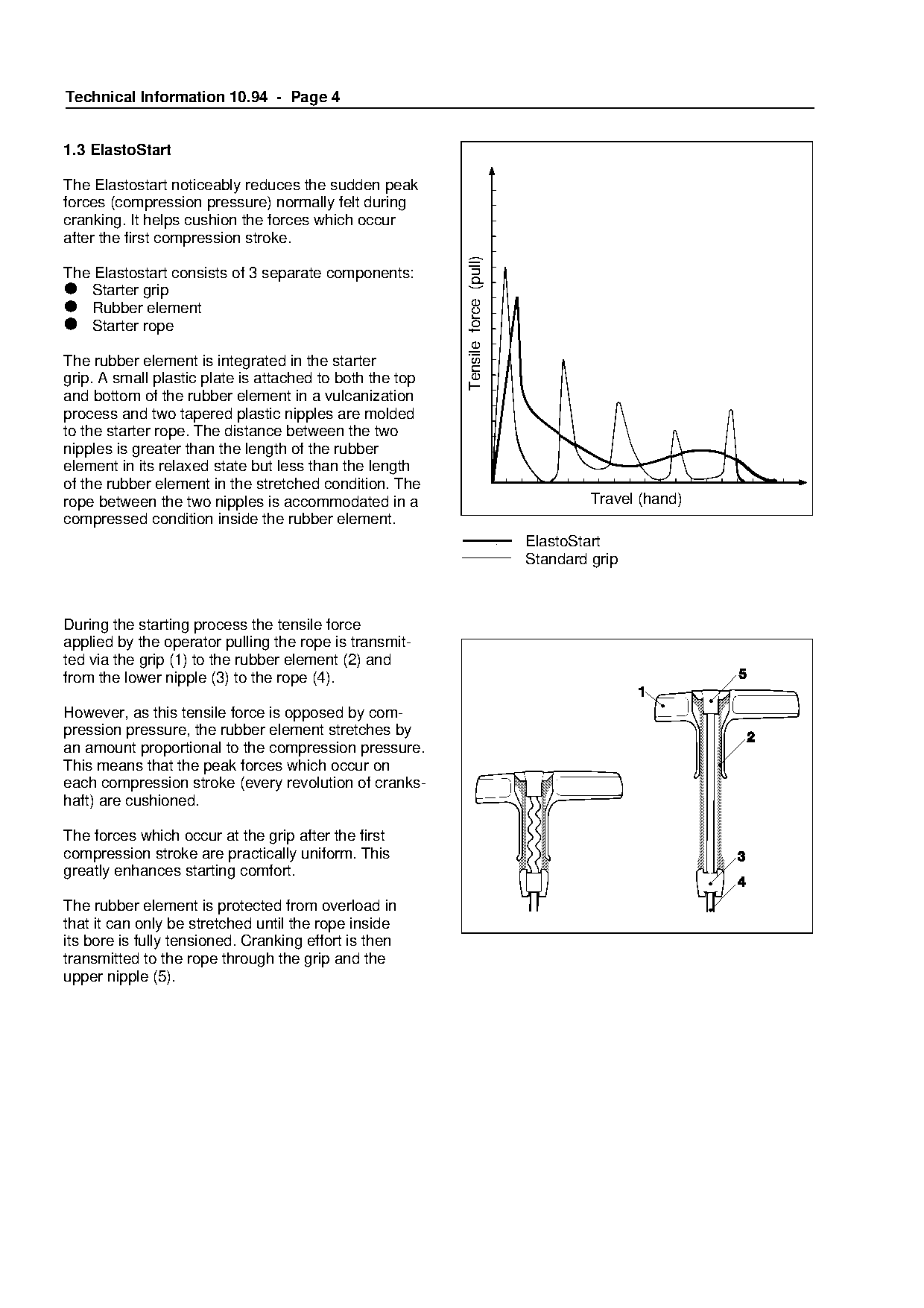
The Elastostart noticeably reduces the sudden peak
forces (compression pressure) normally felt during
cranking. It helps cushion the forces which occur
after the first compression stroke.

                                                           Tensile force (pull)
The Elastostart consists of 3 separate components:
•  Starter grip
•  Rubber element
•  Starter rope

The rubber element is integrated in the starter

grip. A small plastic plate is attached to both the top

and bottom of the rubber element in a vulcanization
process and two tapered plastic nipples are molded
to the starter rope. The distance between the two

nipples is greater than the length of the rubber
element in its relaxed state but less than the length
of the rubber element in the stretched condition. The

rope between the two nipples is accommodated in a                                          Travel (hand)
compressed condition inside the rubber element.

                                                                                  ElastoStart
                                                                                  Standard grip

During the starting process the tensile force

applied by the operator pulling the rope is transmit-
ted via the grip (1) to the rubber element (2) and
from the lower nipple (3) to the rope (4).

However, as this tensile force is opposed by com-
pression pressure, the rubber element stretches by

an amount proportional to the compression pressure.
This means that the peak forces which occur on
each compression stroke (every revolution of cranks-
haft) are cushioned.

The forces which occur at the grip after the first

compression stroke are practically uniform. This
greatly enhances starting comfort.

The rubber element is protected from overload in

that it can only be stretched until the rope inside
its bore is fully tensioned. Cranking effort is then
transmitted to the rope through the grip and the

upper nipple (5).
Page 5 of 6
Text of page 5 — search, copy, screen readers
Technical Information 10.94 - Page 5

2.   Service notes

2.1 Fuel pump

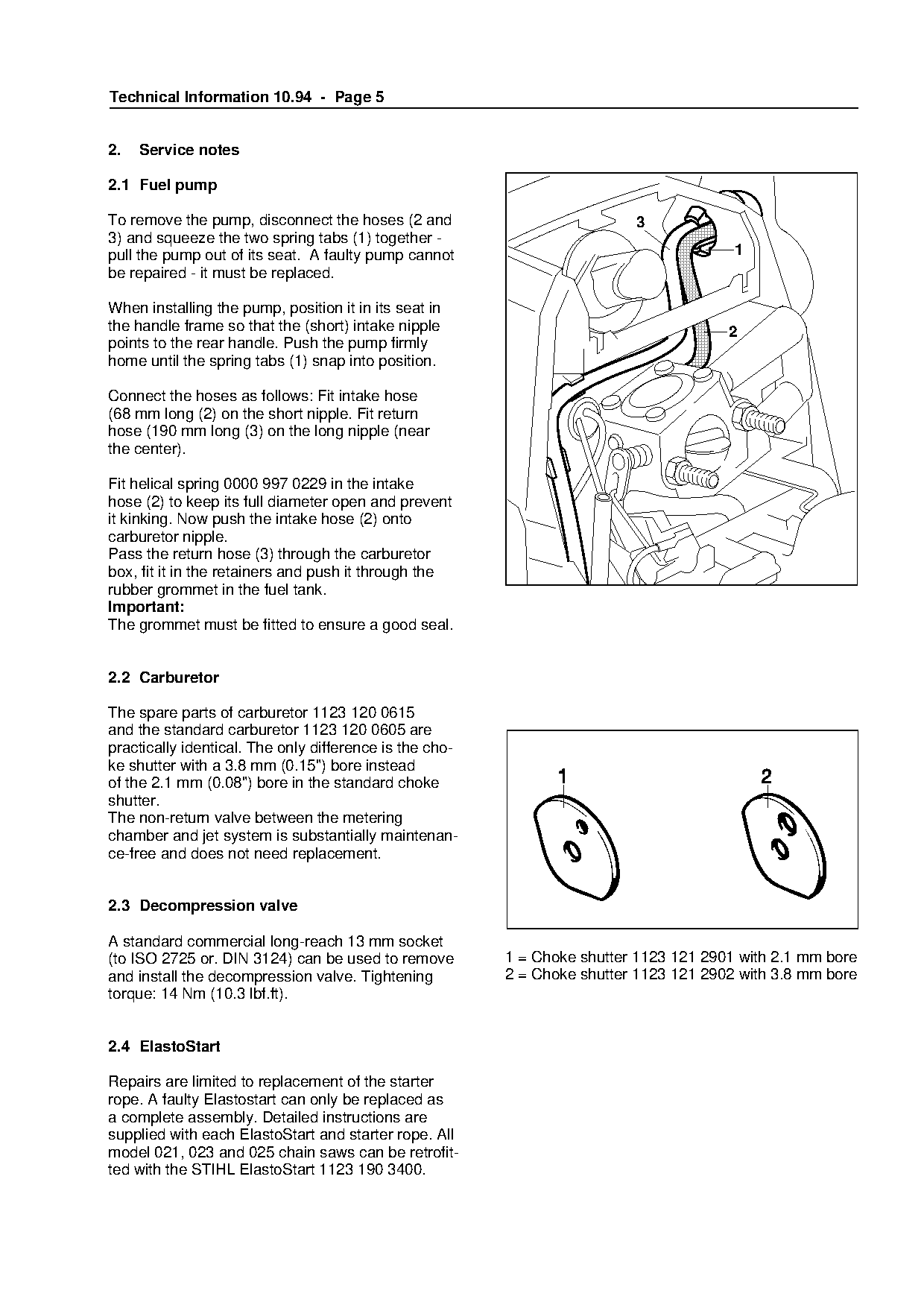
To remove the pump, disconnect the hoses (2 and                           3
3) and squeeze the two spring tabs (1) together -
pull the pump out of its seat. A faulty pump cannot                                     1
be repaired - it must be replaced.

When installing the pump, position it in its seat in
the handle frame so that the (short) intake nipple                                     2
points to the rear handle. Push the pump firmly
home until the spring tabs (1) snap into position.

Connect the hoses as follows: Fit intake hose
(68 mm long (2) on the short nipple. Fit return
hose (190 mm long (3) on the long nipple (near

the center).

Fit helical spring 0000 997 0229 in the intake

hose (2) to keep its full diameter open and prevent
it kinking. Now push the intake hose (2) onto
carburetor nipple.
Pass the return hose (3) through the carburetor
box, fit it in the retainers and push it through the
rubber grommet in the fuel tank.
Important:
The grommet must be fitted to ensure a good seal.

2.2 Carburetor

The spare parts of carburetor 1123 120 0615
and the standard carburetor 1123 120 0605 are

practically identical. The only difference is the cho-
ke shutter with a 3.8 mm (0.15") bore instead
of the 2.1 mm (0.08") bore in the standard choke
shutter.

The non-return valve between the metering
chamber and jet system is substantially maintenan-

ce-free and does not need replacement.

2.3 Decompression valve

A standard commercial long-reach 13 mm socket
(to ISO 2725 or. DIN 3124) can be used to remove         1 = Choke shutter 1123 121 2901 with 2.1 mm bore

and install the decompression valve. Tightening          2 = Choke shutter 1123 121 2902 with 3.8 mm bore
torque: 14 Nm (10.3 lbf.ft).

2.4 ElastoStart

Repairs are limited to replacement of the starter
rope. A faulty Elastostart can only be replaced as
a complete assembly. Detailed instructions are
supplied with each ElastoStart and starter rope. All
model 021, 023 and 025 chain saws can be retrofit-
ted with the STIHL ElastoStart 1123 190 3400.
Page 6 of 6
Text of page 6 — search, copy, screen readers
Technical Information 10.94 - Page 6

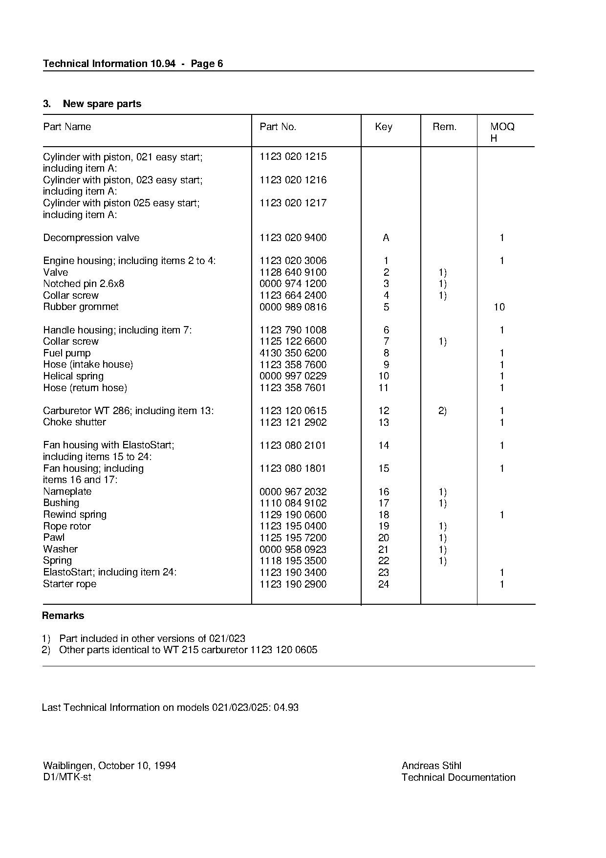
3.   New spare parts

Part Name                                     Part No.         Key           Rem.       MOQ
                                                                                        H
Cylinder with piston, 021 easy start;         1123 020 1215
including item A:
Cylinder with piston, 023 easy start;         1123 020 1216
including item A:
Cylinder with piston 025 easy start;          1123 020 1217
including item A:

Decompression valve                           1123 020 9400        A                      1

Engine housing; including items 2 to 4:       1123 020 3006        1                      1
Valve                                         1128 640 9100        2          1)
Notched pin 2.6x8                             0000 974 1200        3          1)

Collar screw                                  1123 664 2400        4          1)
Rubber grommet                                0000 989 0816        5                     10

Handle housing; including item 7:             1123 790 1008     6                         1
Collar screw                                  1125 122 6600     7             1)
Fuel pump                                     4130 350 6200     8                         1
Hose (intake house)
Helical spring
                                              1123 358 7600
                                              0000 997 0229
                                                              fo9
                                                               10
                                                                                          1
                                                                                          1
Hose (return hose)                            1123 358 7601    11                         1

Carburetor WT 286; including item 13:         1123 120 0615    12             2)          1

Choke shutter                                 1123 121 2902    13                         1

Fan housing with ElastoStart;                 1123 080 2101    14                         1
including items 15 to 24:

Fan housing; including                        1123 080 1801    15                         1
items 16 and 17:

Nameplate                                     0000 967 2032    16             1)
Bushing                                       1110 084 9102    17             1)
Rewind spring                                 1129 190 0600    18                         1
Rope rotor

                                              1123 195 0400    19             1)
Pawl                                          1125 195 7200    20             1)
Washer                                        0000 958 0923    21             1)

Spring                                        1118 195 3500    22             1)
ElastoStart; including item 24:               1123 190 3400    23                         1
Starter rope                                  1123 190 2900    24                         1

Remarks

1) Part included in other versions of 021/023
2) Other parts identical to WT 215 carburetor 1123 120 0605

Last Technical Information on models 021/023/025: 04.93

Waiblingen, October 10, 1994                                           Andreas Stihl
D1/MTK-st                                                              Technical Documentation
Most of these PDFs embed fonts with a shifted character map, so the text above was recovered rather than copied — read it as a faithful but imperfect transcription, and treat the page image above each block as the authority where the two disagree — the figures exist only there, because they are vector drawings that text extraction cannot keep.