Technical Information · issue 17 of 1994
Engine; ignition system; spark plug; fuel pickup b
Model FS 36, 40, 44 Brushcutters - Series 4130
IssueTI 17/1994
From serial 28 222 807, 28 903 005
Full text
Page 1 of 7
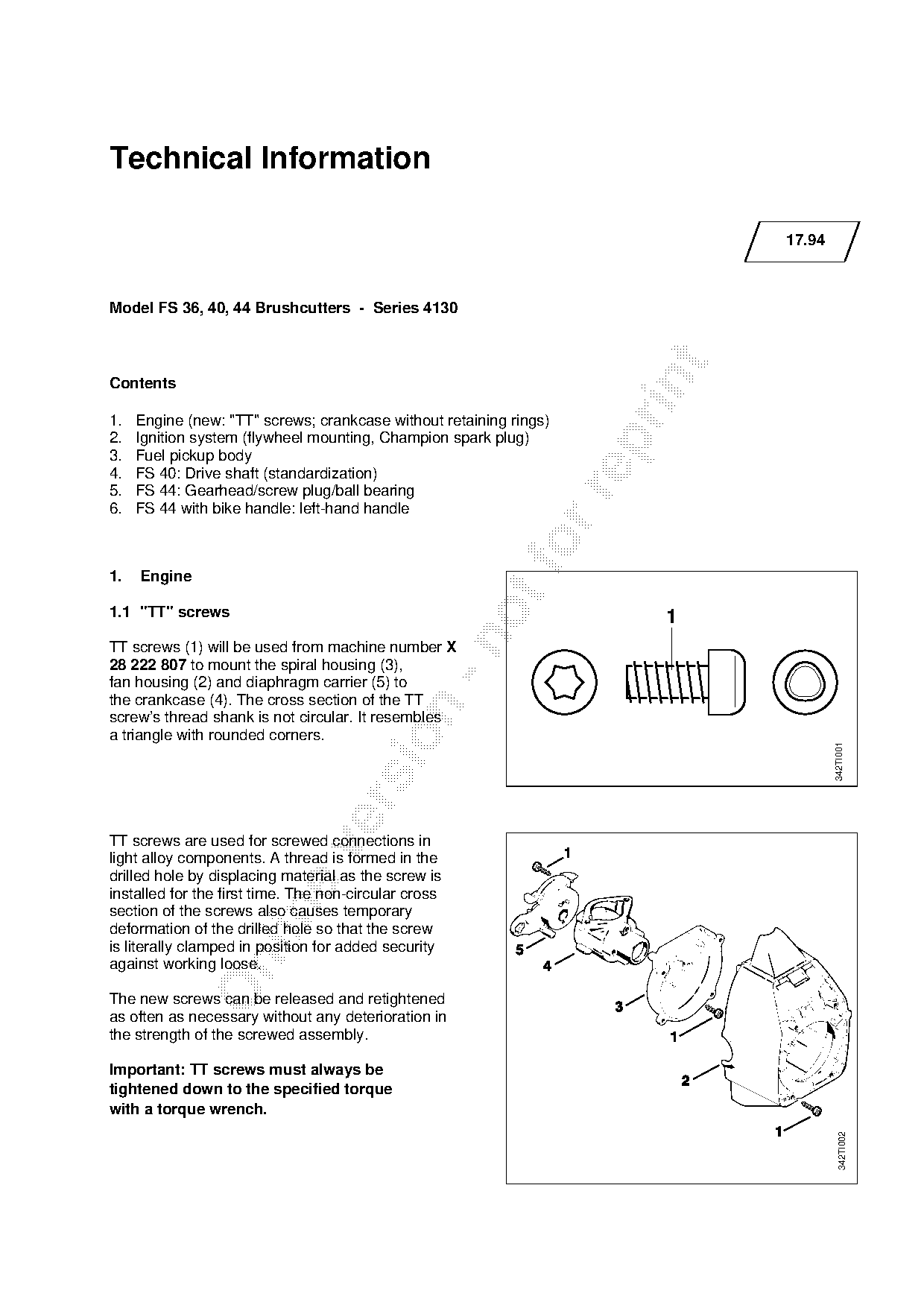
Text of page 1 — search, copy, screen readers
Technical Information

                                                                             17.94

Model FS 36, 40, 44 Brushcutters - Series 4130

Contents

1.   Engine (new: "TT" screws; crankcase without retaining rings)
2.   Ignition system (flywheel mounting, Champion spark plug)

3.   Fuel pickup body
4.   FS 40: Drive shaft (standardization)
5.   FS 44: Gearhead/screw plug/ball bearing

6.   FS 44 with bike handle: left-hand handle

1.   Engine
1.1 "TT" screws                                                          1

TT screws (1) will be used from machine number X
28 222 807 to mount the spiral housing (3),
fan housing (2) and diaphragm carrier (5) to
the crankcase (4). The cross section of the TT

screw’s thread shank is not circular. It resembles
a triangle with rounded corners.

                                                                                     342TI001

TT screws are used for screwed connections in

light alloy components. A thread is formed in the
drilled hole by displacing material as the screw is
installed for the first time. The non-circular cross

section of the screws also causes temporary
deformation of the drilled hole so that the screw
is literally clamped in position for added security

against working loose.

The new screws can be released and retightened
as often as necessary without any deterioration in
the strength of the screwed assembly.

Important: TT screws must always be
tightened down to the specified torque
with a torque wrench.
                                                                                       342TI002
Page 2 of 7
Text of page 2 — search, copy, screen readers
Technical Information 17.94 - Page 2

Spare parts availability
The core holes in the crankcase and spiral
housing have been modified to suit TT screws.
The factory therefore supplies TT screws along
with each replacement crankcase and spiral
housing.

Service notes
The new TT screws supplied with the spiral
housing or crankcase must be used to mount
the components listed in the table. Note the
tightening torques for TT screws when carrying
out repairs.

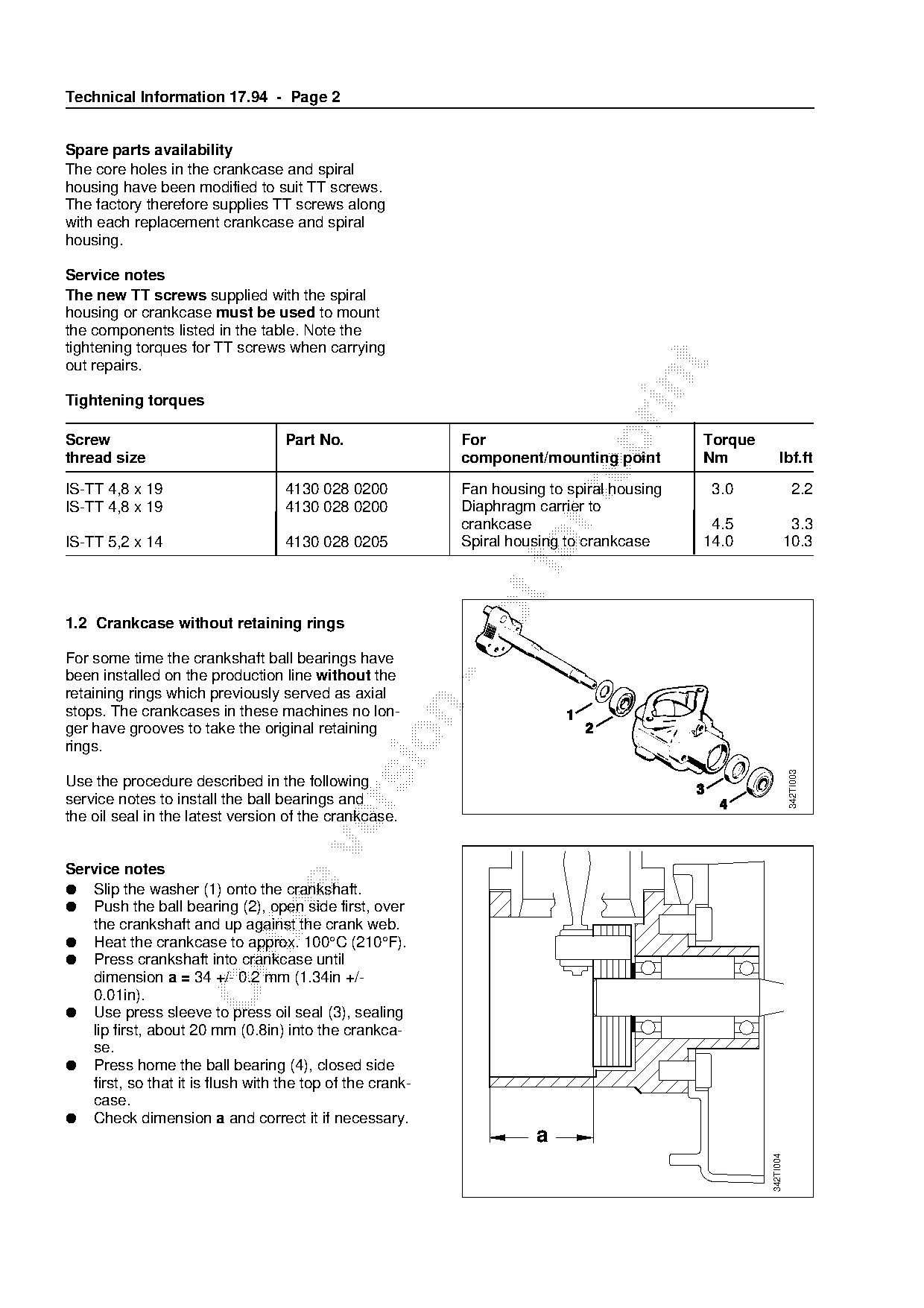
Tightening torques

Screw                              Part No.                For                             Torque
thread size                                                component/mounting point        Nm            lbf.ft

IS-TT 4,8 x 19                     4130 028 0200           Fan housing to spiral housing    3.0                  2.2

IS-TT 4,8 x 19                     4130 028 0200           Diaphragm carrier to
                                                           crankcase                        4.5                 3.3
IS-TT 5,2 x 14                     4130 028 0205
                                                           Spiral housing to crankcase     14.0                10.3

1.2 Crankcase without retaining rings

For some time the crankshaft ball bearings have
been installed on the production line without the
retaining rings which previously served as axial

stops. The crankcases in these machines no lon-
ger have grooves to take the original retaining

rings.

                                                                                                               342TI003
Use the procedure described in the following
service notes to install the ball bearings and

the oil seal in the latest version of the crankcase.

Service notes
● Slip the washer (1) onto the crankshaft.
● Push the ball bearing (2), open side first, over

   the crankshaft and up against the crank web.
● Heat the crankcase to approx. 100°C (210°F).
● Press crankshaft into crankcase until

   dimension a = 34 +/- 0.2 mm (1.34in +/-
   0.01in).
● Use press sleeve to press oil seal (3), sealing
   lip first, about 20 mm (0.8in) into the crankca-
   se.
● Press home the ball bearing (4), closed side
   first, so that it is flush with the top of the crank-
   case.
● Check dimension a and correct it if necessary.
                                                                     a
                                                                                                    342TI004
Page 3 of 7
Text of page 3 — search, copy, screen readers
Technical Information 17.94 - Page 3

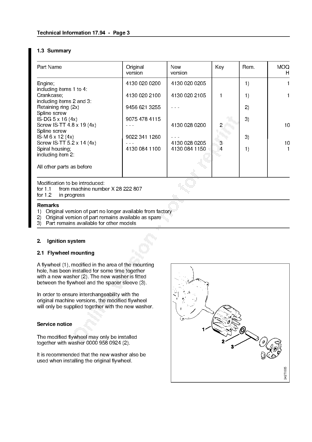
1.3 Summary

Part Name                              Original            New             Key    Rem.   MOQ
                                       version             version                         H
Engine;                                4130 020 0200       4130 020 0205          1)                 1
including items 1 to 4:
Crankcase;                             4130 020 2100       4130 020 2105    1     1)                 1
including items 2 and 3:
Retaining ring (2x)                    9456 621 3255       ---                    2)
Spline screw
IS-DG 5 x 16 (4x)                      9075 478 4115                              3)

Screw IS-TT 4.8 x 19 (4x)              ---                 4130 028 0200    2             10

Spline screw
IS-M 6 x 12 (4x)                       9022 341 1260       ---                    3)
Screw IS-TT 5.2 x 14 (4x)              ---                 4130 028 0205    3             10

Spiral housing;                        4130 084 1100       4130 084 1150    4     1)       1
including item 2:

All other parts as before

Modification to be introduced:
for 1.1 from machine number X 28 222 807
for 1.2 in progress
Remarks
1) Original version of part no longer available from factory

2) Original version of part remains available as spare
3) Part remains available for other models

2.   Ignition system

2.1 Flywheel mounting

A flywheel (1), modified in the area of the mounting
hole, has been installed for some time together

with a new washer (2). The new washer is fitted
between the flywheel and the spacer sleeve (3).

In order to ensure interchangeability with the
original machine versions, the modified flywheel
will only be supplied together with the new washer.

Service notice

The modified flywheel may only be installed
together with washer 0000 958 0924 (2).

It is recommended that the new washer also be
used when installing the original flywheel.
                                                                                          342TI005
Page 4 of 7
Text of page 4 — search, copy, screen readers
Technical Information 17.94 - Page 4

2.2 Spark plug

The GM AC CSR 45 spark plug (made by General
Motors) installed on the production line will be
replaced in the near future by the new RCJ8 spark
plug (made by Champion).

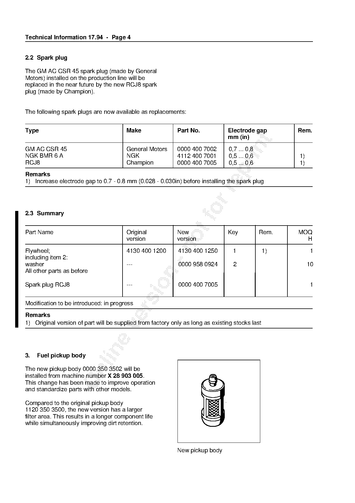
The following spark plugs are now available as replacements:

Type                                     Make               Part No.            Electrode gap         Rem.
                                                                                mm (in)

GM AC CSR 45                             General Motors     0000 400 7002        0,7 ... 0,8
NGK BMR 6 A                              NGK                4112 400 7001        0,5 ... 0,6          1)
RCJ8                                     Champion           0000 400 7005        0,5 ... 0,6          1)

Remarks
1) Increase electrode gap to 0.7 - 0.8 mm (0.028 - 0.030in) before installing the spark plug

2.3 Summary                                                           fo
Part Name                                Original           New                 Key            Rem.   MOQ
                                         version            version                                     H

Flywheel;                                4130 400 1200      4130 400 1250         1              1)        1
including item 2:
washer                                   ---                0000 958 0924          2                       10
All other parts as before

Spark plug RCJ8                          ---                0000 400 7005                                  1

Modification to be introduced: in progress

Remarks
1) Original version of part will be supplied from factory only as long as existing stocks last

3.   Fuel pickup body

The new pickup body 0000 350 3502 will be

installed from machine number X 28 903 005.
This change has been made to improve operation
and standardize parts with other models.
                                                                                         1
Compared to the original pickup body
1120 350 3500, the new version has a larger
filter area. This results in a longer component life
while simultaneously improving dirt retention.

                                                            New pickup body
Page 5 of 7
Text of page 5 — search, copy, screen readers
Technical Information 17.94 - Page 5

Summary

Part Name                               Original           New             Key       Rem.   MOQ
                                        version            version                            H
Pickup body                             1120 350 3500      0000 350 3502             1)       1

Modification to be introduced from machine number X 28 903 005
Remarks
1) Original version of part no longer available from factory

4.   Drive shaft (FS 40)

Drive shaft 4133 711 3215 has been installed

for some time in place of the original version
4130 711 3205 in order to standardize parts with
the FS 74 brushcutter.

Summary
Part Name                               Original           New             Key       Rem.   MOQ
                                        version            version                            H

Drive shaft                             4130 711 3205      4133 711 3215             1)       1

Modification to be introduced: in progress

Remarks
1) Original version of part no longer available from factory

5.   Gearhead (FS 44)

5.1 Screw plug

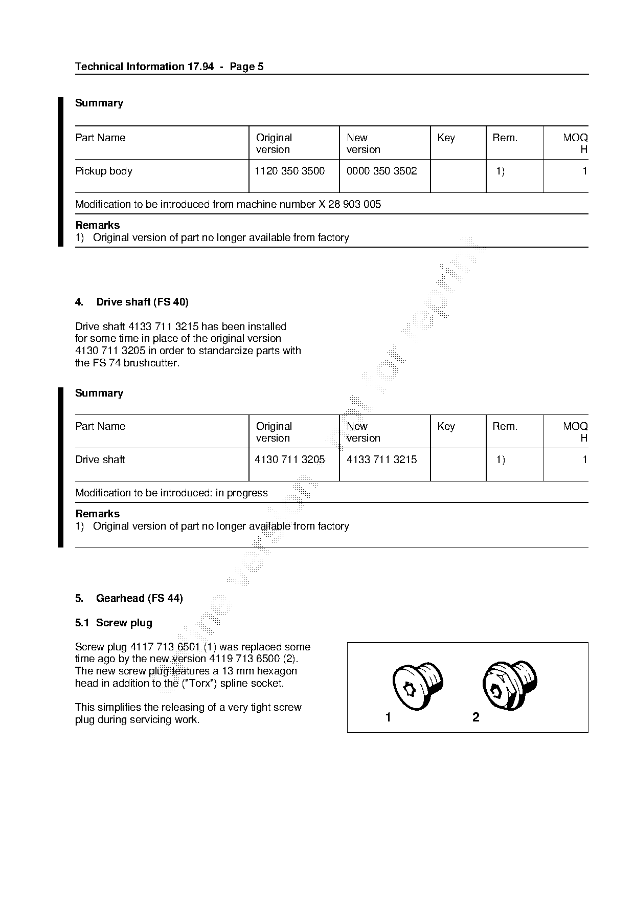
Screw plug 4117 713 6501 (1) was replaced some
time ago by the new version 4119 713 6500 (2).

The new screw plug features a 13 mm hexagon
head in addition to the ("Torx") spline socket.

This simplifies the releasing of a very tight screw
plug during servicing work.                                          1           2
Page 6 of 7
Text of page 6 — search, copy, screen readers
Technical Information 17.94 - Page 6

5.2 Ball bearing

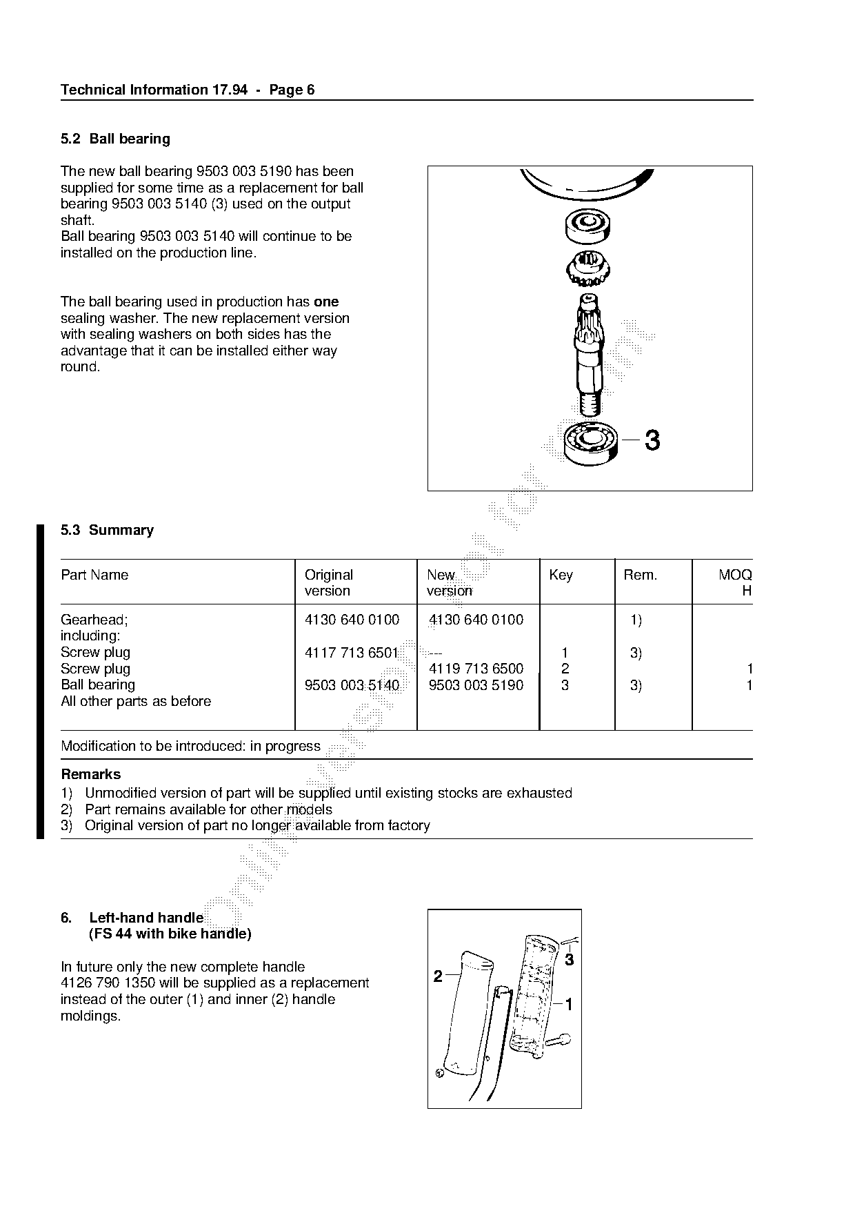
The new ball bearing 9503 003 5190 has been
supplied for some time as a replacement for ball
bearing 9503 003 5140 (3) used on the output
shaft.
Ball bearing 9503 003 5140 will continue to be
installed on the production line.

The ball bearing used in production has one
sealing washer. The new replacement version
with sealing washers on both sides has the

advantage that it can be installed either way

round.

5.3 Summary
Part Name                              Original           New                 Key     Rem.   MOQ
                                       version            version                              H

Gearhead;                              4130 640 0100      4130 640 0100               1)
including:
Screw plug                             4117 713 6501      ---                   1     3)

Screw plug                                                4119 713 6500         2              1

Ball bearing                           9503 003 5140      9503 003 5190         3     3)       1
All other parts as before

Modification to be introduced: in progress
Remarks

1) Unmodified version of part will be supplied until existing stocks are exhausted
2) Part remains available for other models
3) Original version of part no longer available from factory

6.   Left-hand handle
     (FS 44 with bike handle)

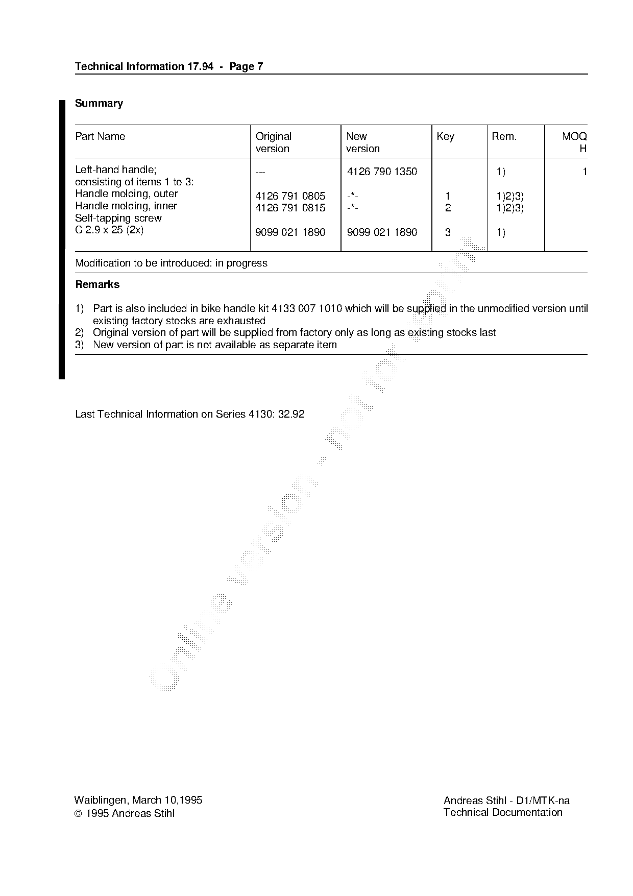
In future only the new complete handle
4126 790 1350 will be supplied as a replacement
instead of the outer (1) and inner (2) handle
moldings.
Page 7 of 7
Text of page 7 — search, copy, screen readers
Technical Information 17.94 - Page 7
Summary
Part Name Original New Key Rem. MOQ
version version H
Left-hand handle; --- 4126 790 1350 1) 1
consisting of items 1 to 3:
Handle molding, outer 4126 791 0805 -*- 1 1)2)3)
Handle molding, inner 4126 791 0815 -*- 2 1)2)3)
Self-tapping screw
C 2.9 x 25 (2x) 9099 021 1890 9099 021 1890 3 1)
Modification to be introduced: in progress
Remarks
1) Part is also included in bike handle kit 4133 007 1010 which will be supplied in the unmodified version until
existing factory stocks are exhausted
2) Original version of part will be supplied from factory only as long as existing stocks last
3) New version of part is not available as separate item
Last Technical Information on Series 4130: 32.92
Waiblingen, March 10,1995 Andreas Stihl - D1/MTK-na
1995 Andreas Stihl Technical Documentation Most of these PDFs embed fonts with a shifted character map, so the text above was recovered rather than copied — read it as a faithful but imperfect transcription, and treat the page image above each block as the authority where the two disagree — the figures exist only there, because they are vector drawings that text extraction cannot keep.