Technical Information · issue 18 of 1994
New FS 420 L version; drive tube; drive shaft; cyl
Model FS 360 and FS 420 Clearing Saws - Series 4116
IssueTI 18/1994
From serial 28 002 415, 28 698 911
Full text
Page 1 of 6
Text of page 1 — search, copy, screen readers
Technical Information

                                                                                               18.94

Model FS 360 and FS 420 Clearing Saws - Series 4116

Contents

1. New FS 420 L version

2. Drive tube, drive shaft
3. Cylinder/crankcase (FS 360),
   (hole pattern same as FS 420)

4. Clutch housing (rubber rings deleted)
5. Clutch (shoes without linings),
   clutch drum

6. Tank housing (tubular rivets)
7. Screen/shroud (new screws)
8. Filter mat (special accessory)

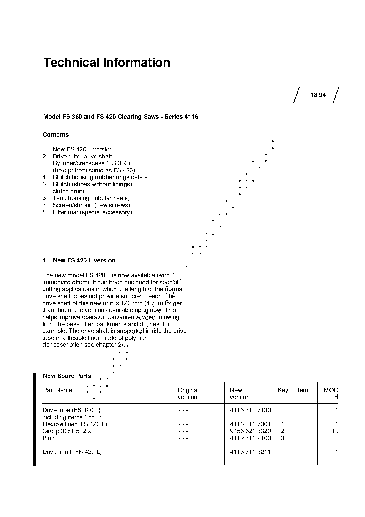
1. New FS 420 L version

The new model FS 420 L is now available (with

immediate effect). It has been designed for special
cutting applications in which the length of the normal

drive shaft does not provide sufficient reach. The
drive shaft of this new unit is 120 mm (4.7 in) longer
than that of the versions available up to now. This

helps improve operator convenience when mowing
from the base of embankments and ditches, for
example. The drive shaft is supported inside the drive

tube in a flexible liner made of polymer
(for description see chapter 2).

New Spare Parts

Part Name                                         Original        New             Key   Rem.       MOQ
                                                  version         version                            H

Drive tube (FS 420 L);                            ---             4116 710 7130                        1
including items 1 to 3:
Flexible liner (FS 420 L)                         ---             4116 711 7301    1                    1
Circlip 30x1.5 (2 x)                              ---             9456 621 3320    2                   10
Plug                                              ---             4119 711 2100    3

Drive shaft (FS 420 L)                            ---             4116 711 3211                        1
Page 2 of 6
Text of page 2 — search, copy, screen readers
Technical Information 18.94 - Page 2

2.   Drive tube, drive shaft

In future the drive shaft will be located and supported inside the drive tube in a flexible polymer liner instead
of the previous arrangement with five rubber-mounted bushes. The flexible liner can be replaced if it wears.

The flexible liner is located axially by a circlip installed at each end. The original drive shaft, which was
hardened in the area of the five bearings, has been discontinued and replaced by the new drive shaft
4116 711 3212.

Service note

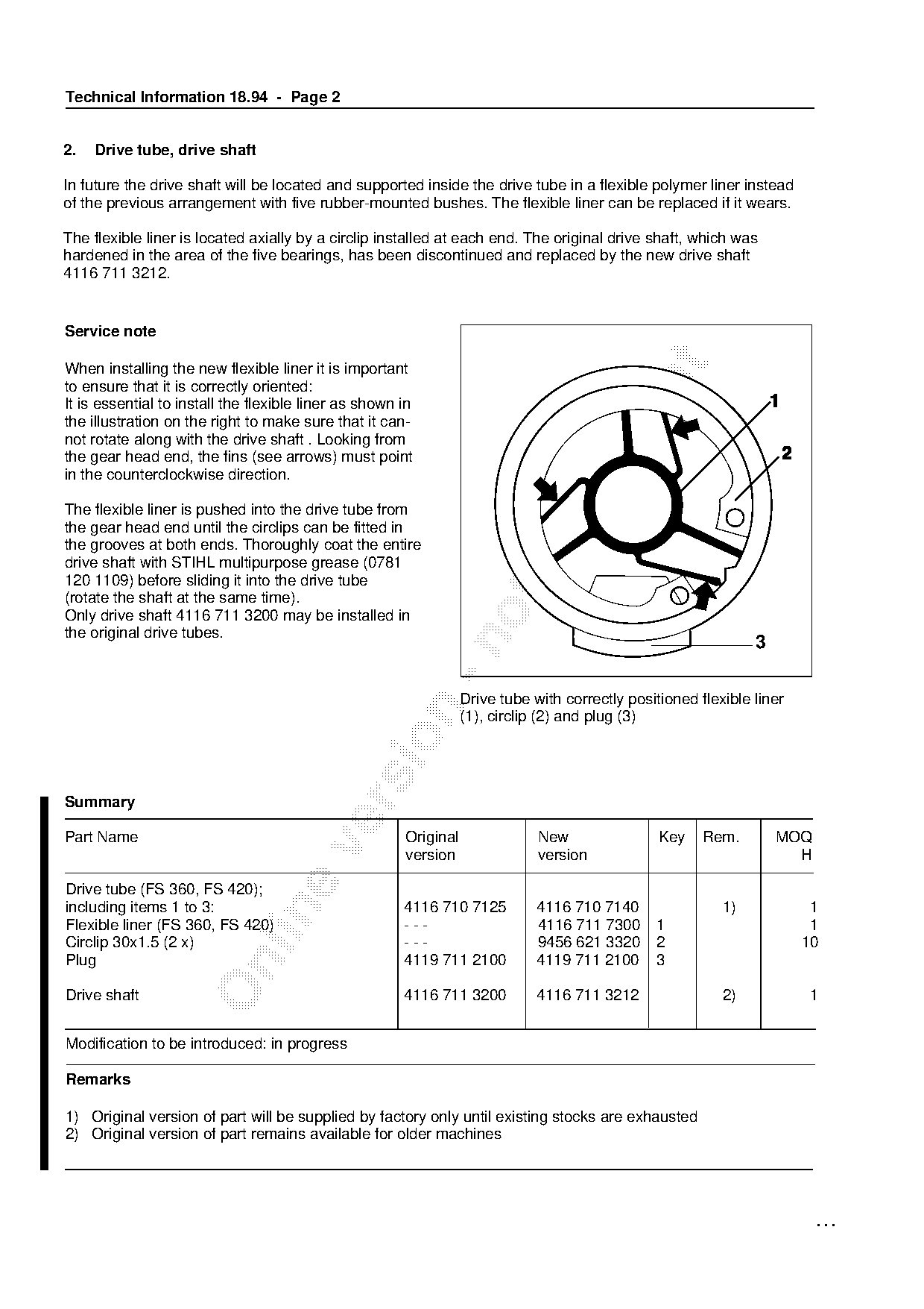
When installing the new flexible liner it is important

to ensure that it is correctly oriented:
It is essential to install the flexible liner as shown in
the illustration on the right to make sure that it can-
not rotate along with the drive shaft . Looking from

the gear head end, the fins (see arrows) must point
in the counterclockwise direction.

The flexible liner is pushed into the drive tube from
the gear head end until the circlips can be fitted in
the grooves at both ends. Thoroughly coat the entire
drive shaft with STIHL multipurpose grease (0781
120 1109) before sliding it into the drive tube
(rotate the shaft at the same time).
Only drive shaft 4116 711 3200 may be installed in
the original drive tubes.


                                                                  Drive tube with correctly positioned flexible liner

                                                                  (1), circlip (2) and plug (3)

Summary

Part Name                                              Original               New                Key    Rem.        MOQ

                                                       version                version                                 H

Drive tube (FS 360, FS 420);
including items 1 to 3:                                4116 710 7125          4116 710 7140                1)            1

Flexible liner (FS 360, FS 420)                        ---                    4116 711 7300     1                        1
Circlip 30x1.5 (2 x)                                   ---                    9456 621 3320     2                       10
Plug                                                   4119 711 2100          4119 711 2100     3

Drive shaft                                            4116 711 3200          4116 711 3212                2)           1

Modification to be introduced: in progress

Remarks

1) Original version of part will be supplied by factory only until existing stocks are exhausted
2) Original version of part remains available for older machines

                                                                                                                          ...
Page 3 of 6
Text of page 3 — search, copy, screen readers
Technical Information 18.94 Page 3

3. Cylinder/crankcase (FS 360)

In order to simplify parts inventories and repairs, the        Service notes and parts availability
hole pattern of the cylinder-to-crankcase joint on the
FS 360 will be changed from machine                            Crankcase 4116 020 2115, cylinder gasket
number X 28 698 911 to match the hole pattern of               4116 029 2305 and the new cylinder with 44 mm
the FS 420. The new part number of the cylinder                piston 4116 020 1202 must be used for repairs to
with 44 mm piston (with new hole pattern) is                   the FS 360 from machine number X 28 698 911.
4116 020 1202.                                                 The original versions of the crankcase, cylinder
This modification means that the crankcase                     with piston and cylinder gasket remain available for
4116 020 2115 and cylinder gasket 4116 029 2305,               repairs to FS 360 units prior to the above-mentioned
previously used only for the FS 420, will now fit              machine number.
the FS 360 as well.

Summary

Part Name                                           Original              New              Key      Rem.    MOQ
                                                    version               version                             H

Crankcase                                           4116 020 2105         4116 020 2115               1)         1
Cylinder with piston;                               4116 020 1201         4116 020 1202               1)         1
including:
Piston;
                                                    4116 030 2000         4116 030 2000
including:
Piston ring                                         4116 034 3000         4116 034 3000

Cylinder gasket                                     4116 029 2300         4116 029 2305               1)       10

All other parts as before

Modification to be introduced from machine number X 28 698 911

Remarks

1) Original version of part remains available for older machines

4. Clutch housing

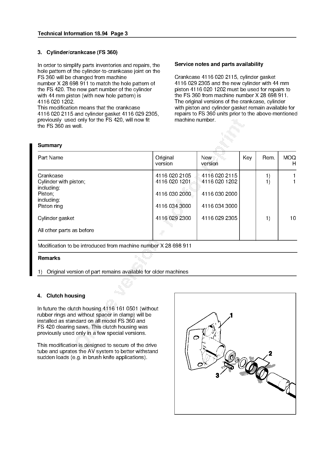
In future the clutch housing 4116 161 0501 (without

rubber rings and without spacer in clamp) will be
installed as standard on all model FS 360 and
FS 420 clearing saws. This clutch housing was

previously used only in a few special versions.

This modification is designed to secure of the drive
tube and uprates the AV system to better withstand
sudden loads (e.g. in brush knife applications).
Page 4 of 6
Text of page 4 — search, copy, screen readers
Technical Information 18.94 - Page 4

Summary

Part Name                                          Original              New               Key      Rem.     MOQ
                                                   version               version                               H

Clutch housing;                                    4116 160 0600         4116 161 0501     1         1)          1
including:
Rubber ring (2 x)                                  4116 791 9600         ---               2         2)
Spacer                                             4116 162 9800         ---               3         2)

All other parts as before
Modification to be introduced: in progress

Remarks

1) Original version of part will be supplied by factory only until existing stocks are exhausted

2) Original version of part remains available for older machines

5. Clutch, clutch drum

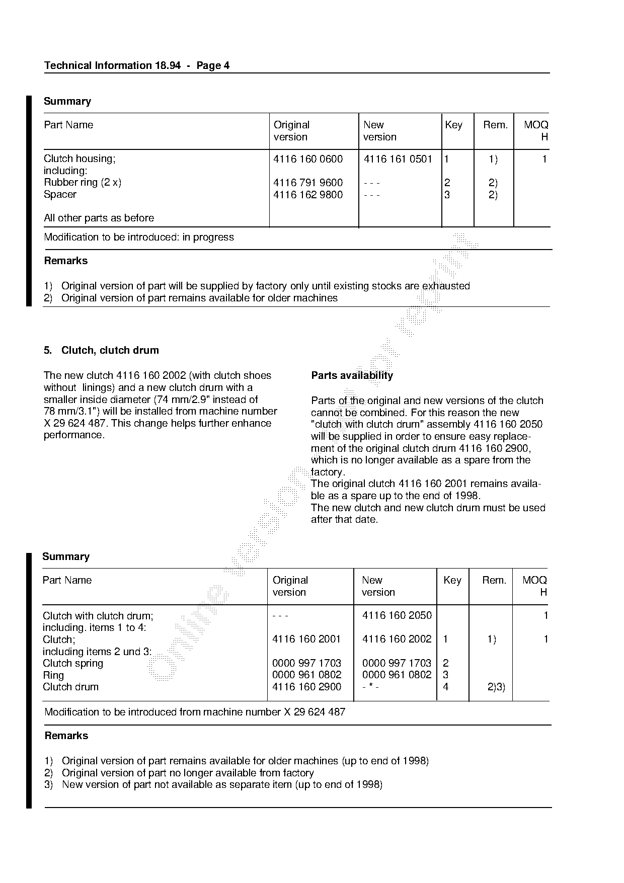
The new clutch 4116 160 2002 (with clutch shoes
without linings) and a new clutch drum with a
                                                              Parts availability

smaller inside diameter (74 mm/2.9" instead of                Parts of the original and new versions of the clutch
78 mm/3.1") will be installed from machine number             cannot be combined. For this reason the new
X 29 624 487. This change helps further enhance               "clutch with clutch drum" assembly 4116 160 2050

performance.                                                  will be supplied in order to ensure easy replace-
                                                              ment of the original clutch drum 4116 160 2900,
                                                              which is no longer available as a spare from the
                                                              factory.

                                                              The original clutch 4116 160 2001 remains availa-
                                                              ble as a spare up to the end of 1998.

                                                              The new clutch and new clutch drum must be used
                                                              after that date.

Summary

Part Name                                          Original              New               Key     Rem.     MOQ
                                                   version               version                              H

Clutch with clutch drum;                           ---                   4116 160 2050                           1
including. items 1 to 4:
Clutch;                                            4116 160 2001         4116 160 2002     1         1)          1

including items 2 und 3:
Clutch spring                                      0000 997 1703         0000 997 1703     2
Ring                                               0000 961 0802         0000 961 0802     3
Clutch drum                                        4116 160 2900         -*-               4         2)3)

Modification to be introduced from machine number X 29 624 487

Remarks

1) Original version of part remains available for older machines (up to end of 1998)
2) Original version of part no longer available from factory
3) New version of part not available as separate item (up to end of 1998)
Page 5 of 6
Text of page 5 — search, copy, screen readers
Technical Information 18.94 Page 5

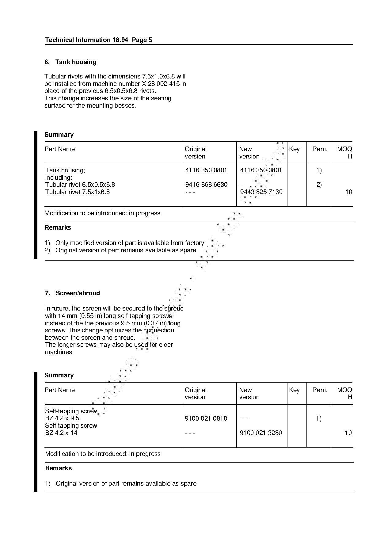
6. Tank housing

Tubular rivets with the dimensions 7.5x1.0x6.8 will
be installed from machine number X 28 002 415 in
place of the previous 6.5x0.5x6.8 rivets.
This change increases the size of the seating
surface for the mounting bosses.

Summary

Part Name                                             Original         New             Key   Rem.   MOQ

                                                      version          version                        H

Tank housing;                                         4116 350 0801    4116 350 0801          1)
including:

Tubular rivet 6.5x0.5x6.8                             9416 868 6630   ---                     2)
Tubular rivet 7.5x1x6.8                               ---              9443 825 7130                 10

Modification to be introduced: in progress

Remarks                                                          fo
1) Only modified version of part is available from factory
2) Original version of part remains available as spare

7. Screen/shroud

In future, the screen will be secured to the shroud
with 14 mm (0.55 in) long self-tapping screws
instead of the the previous 9.5 mm (0.37 in) long

screws. This change optimizes the connection
between the screen and shroud.
The longer screws may also be used for older

machines.

Summary

Part Name                                             Original         New             Key   Rem.   MOQ

                                                      version          version                        H

Self-tapping screw
BZ 4.2 x 9.5                                          9100 021 0810    ---                   1)
Self-tapping screw
BZ 4.2 x 14                                           ---              9100 021 3280                 10

Modification to be introduced: in progress

Remarks

1) Original version of part remains available as spare
Page 6 of 6
Text of page 6 — search, copy, screen readers
Technical Information 18.94 - Page 6

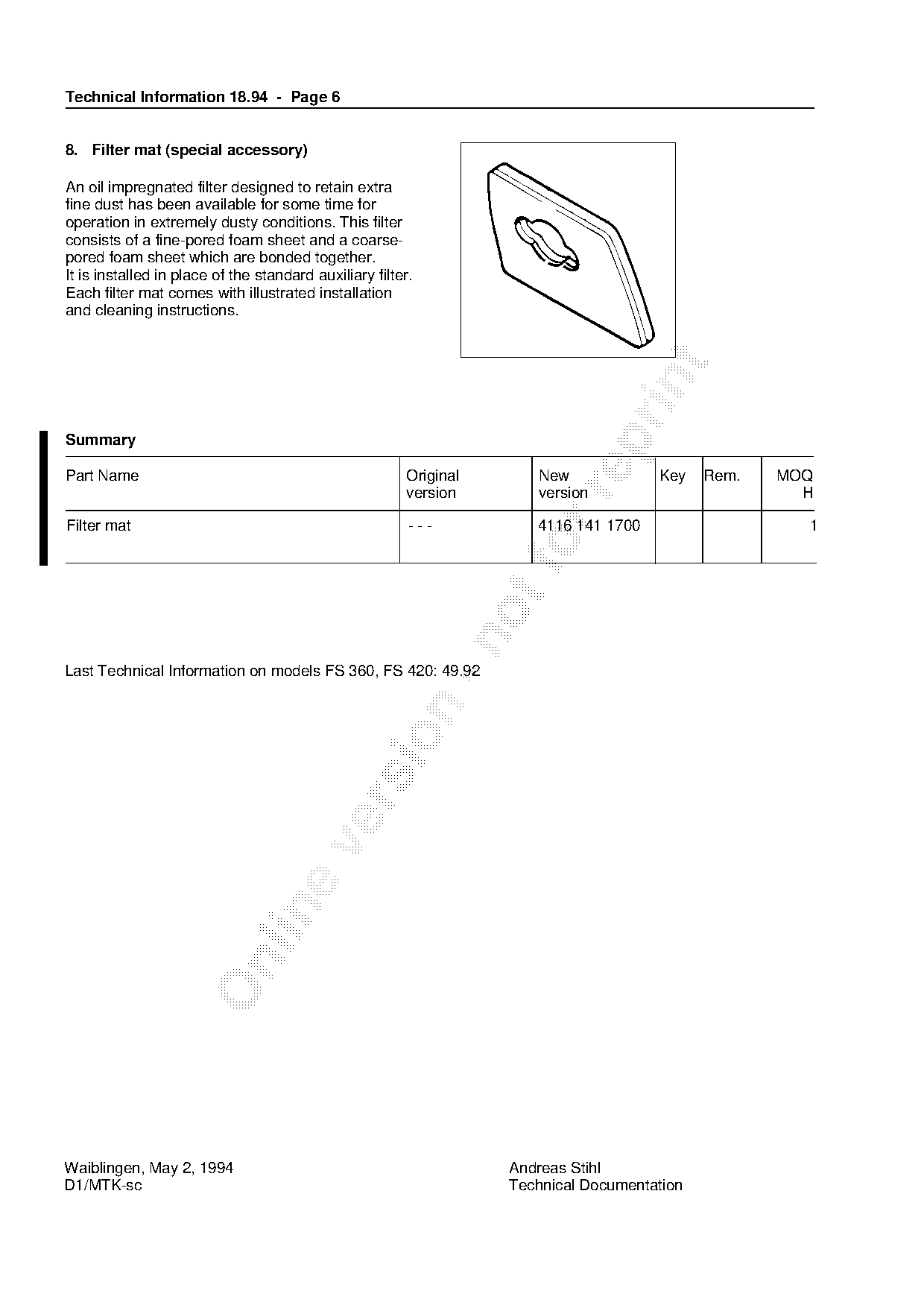
8. Filter mat (special accessory)

An oil impregnated filter designed to retain extra
fine dust has been available for some time for
operation in extremely dusty conditions. This filter
consists of a fine-pored foam sheet and a coarse-
pored foam sheet which are bonded together.
It is installed in place of the standard auxiliary filter.
Each filter mat comes with illustrated installation
and cleaning instructions.

Summary

Part Name                                               Original       New             Key    Rem.   MOQ

                                                        version        version                         H

Filter mat                                               ---           4116 141 1700                   1

Last Technical Information on models FS 360, FS 420: 49.92

Waiblingen, May 2, 1994                                             Andreas Stihl
D1/MTK-sc                                                           Technical Documentation
Most of these PDFs embed fonts with a shifted character map, so the text above was recovered rather than copied — read it as a faithful but imperfect transcription, and treat the page image above each block as the authority where the two disagree — the figures exist only there, because they are vector drawings that text extraction cannot keep.