Technical Information · issue 20 of 1994
Water pumps P 835, P 840
IssueTI 20/1994
Full text
Page 1 of 6
Text of page 1 — search, copy, screen readers
Technical Information

                                                                                                 20.94

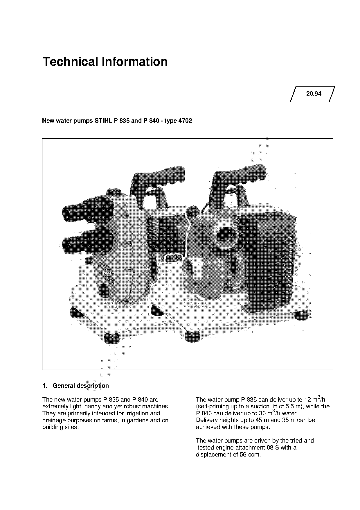
New water pumps STIHL P 835 and P 840 - type 4702

1. General description

The new water pumps P 835 and P 840 are             The water pump P 835 can deliver up to 12 m3/h
extremely light, handy and yet robust machines.     (self-priming up to a suction lift of 5.5 m), while the
They are primarily intended for irrigation and      P 840 can deliver up to 30 m3/h water.
drainage purposes on farms, in gardens and on       Delivery heights up to 45 m and 35 m can be
building sites.                                     achieved with these pumps.

                                                    The water pumps are driven by the tried-and-
                                                     tested engine attachment 08 S with a
                                                    displacement of 56 ccm.
Page 2 of 6
Text of page 2 — search, copy, screen readers
Technical Information 20.94 - Page 2

2.   Technical description

2.1 Engine

The power unit is based on the same compact
two-stroke engine that is also used in the 08 S
chain saw and in a number of STIHL BT and TS
series. The robust design permits its use even in
tough conditions. It is mechanically designed to
prevent accidental contact with hot engine parts.

2.2 Pump

The pumps operate on the centrifugal principle.

The pump housing comprises two diecast parts

(corrosion-proof aluminium alloy) which are bonded
and additionally screwed together. The intake and
delivery ports are screwed onto the pump housing.

The intake port ends directly at the open blade side
of the pump impeller where it is fitted with a
vulcanized elastic ring protecting the ends of the
blades against abrasion due to impurities.                    fo
The pump impeller (impeller wheel) is made of a
bronze alloy. An axial face seal ensures that the
pump impeller is sealed off from the pump housing.

The seal is made up of rubber and ceramic sealing
elements.

The water pump P 835 is a self-priming pump up

to a suction lift of 5.5 metres. Sufficient water must
be present in the pump housing for operation.

The water pump P 840, on the other hand, must
always be operated with a foot valve which is fitted
at the end of the suction hose. The pump and

suction hose must be filled with water before it is
started up. Water must overflow through the opening

in the pump housing in order to ensure that there is
also sufficient water present in the suction hose.

Important!

The water pumps must never be allowed to run dry,
otherwise the axial face seal will be damaged.
Page 3 of 6
Text of page 3 — search, copy, screen readers
Technical Information 20.94 - Page 3

3.    Technical Data

3.1. Engine

Displacement:                   56 cm3
Bore:                           47 mm
Stroke:                         32 mm
Compression ratio:              9.5:1
Power output (DIN 70 020)       2.5 kW (3.4 PS)
max. torque
at 5,000 r.p.m.:                3.7 Nm
Crankshaft:                     Two-part, drop forged
Crankshaft bearings:            Two deep groove ball bearings

Crankpin diameter:              14.4 mm

Big-end bearing:                Needle cage
Connecting rod length:          58 mm
Piston pin diameter:            12 mm

Small-end bearing:              Needle cage
Rewind starter:                 Pawl system with automatic
                                rope rewind system

Starter rope:                   4.5 mm dia., 1000 mm long
Crankcase leakage test
at gauge pressure:              pü = 0.4 bar (5.8 psi)
under vacuum:                   pü = 0.4 bar (5.8 psi)      fo
3.2 Fuel System

Carburetor:                     All position diaphragm carburetor with
                                integral fuel pump
(Standard setting)
High speed adjusting screw H:   Back off approx. 1 turn

Low speed adjusting screw L:    Back off approx. 1 turn
Carburetor leakage test

at gauge pressure:              pü = 0.4 bar (5.8 psi)
Fuel tank capacity:             2.65 l (2650 cm3)
Octane number:                  min. 90 RON

Fuel mixture:                   Regular brand-name gasoline and brand-name two-stroke engine oil
Mix ratio:                      1:50
                                with STIHL two-stroke engine oil 1:50

                                1:40 with other brand-name two-stroke engine oils
Air filter:                     Round filter with foam

3.3 Ignition System

Principle of operation:         Contact ignition

Ignition timing:                2.0 ... 2.4 mm B.T.D.C.
Spark plug:                     Bosch WR 7 AC
Electrode gap:                  0.5 mm
Spark plug thread:              M 14 x 1.25; 12.7 mm long
Heat range:                     175
Page 4 of 6
Text of page 4 — search, copy, screen readers
Technical Information 20.94 - Page 4

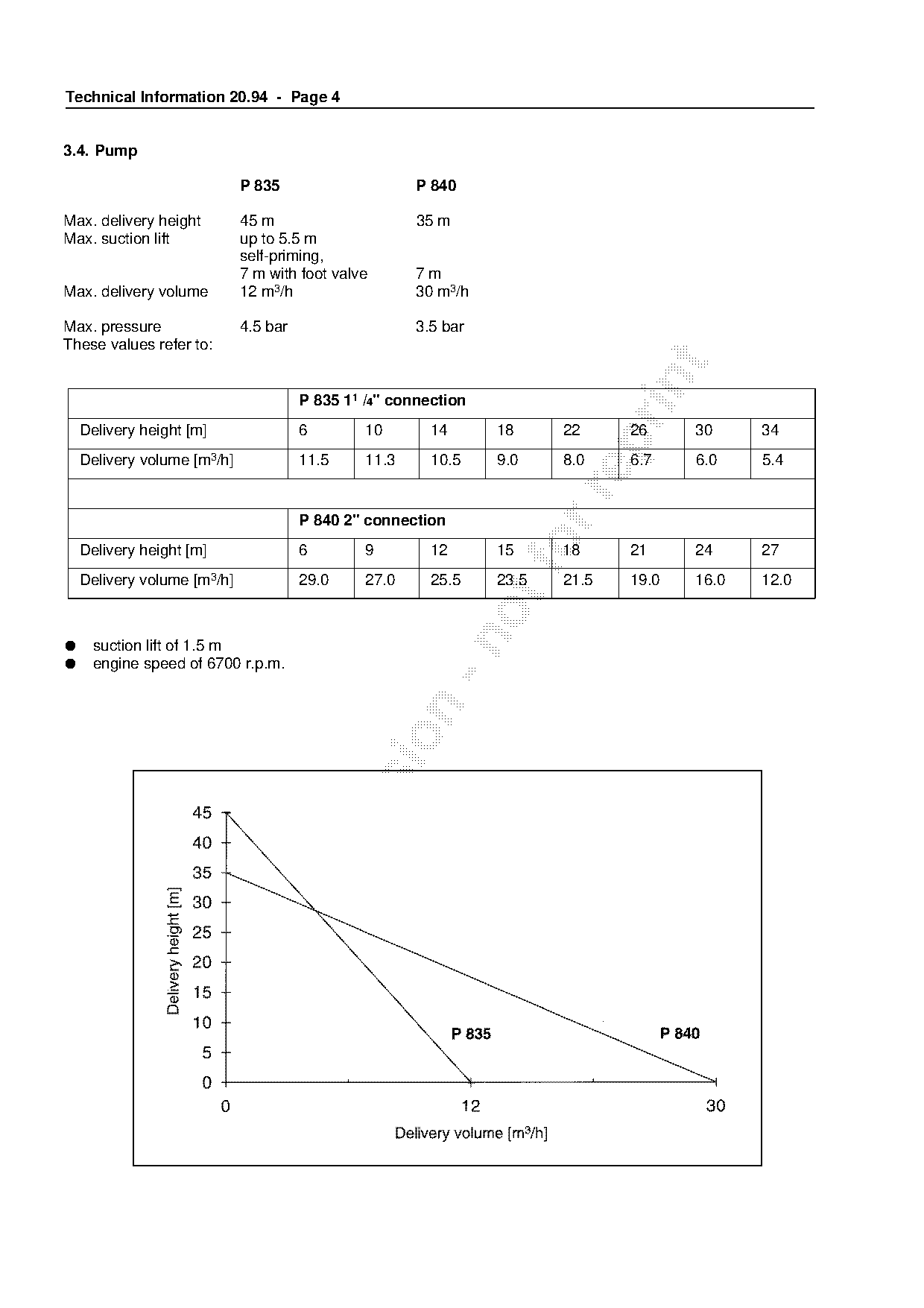
3.4. Pump

                             P 835                     P 840

Max. delivery height         45 m                      35 m
Max. suction lift            up to 5.5 m
                             self-priming,
                             7 m with foot valve       7m
Max. delivery volume         12 m3/h                   30 m3/h

Max. pressure                4.5 bar                   3.5 bar
These values refer to:

                                       P 835 11 /4" connection
    Delivery height [m]                6        10       14      18     22     26     30     34

    Delivery volume [m3/h]             11.5     11.3     10.5    9.0    8.0    6.7    6.0    5.4

                                       P 840 2" connection
    Delivery height [m]                6        9        12      15   fo18     21     24     27
    Delivery volume [m3/h]             29.0     27.0     25.5    23.5   21.5   19.0   16.0   12.0

●    suction lift of 1.5 m
●    engine speed of 6700 r.p.m.
Page 5 of 6
Text of page 5 — search, copy, screen readers
Technical Information 20.94 - Page 5

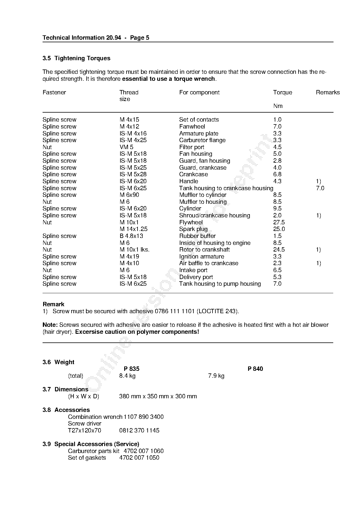
3.5 Tightening Torques

The specified tightening torque must be maintained in order to ensure that the screw connection has the re-
quired strength. It is therefore essential to use a torque wrench.

Fastener                     Thread                 For component                       Torque           Remarks
                             size
                                                                                        Nm

Spline screw                 M 4x15                 Set of contacts                  1.0
Spline screw                 M 4x12                 Fanwheel                         7.0
Spline screw                 IS-M 4x16              Armature plate                   3.3
Spline screw                 IS-M 4x25              Carburetor flange                3.3

Nut                          VM 5                   Filter port                      4.5

Spline screw                 IS-M 5x18              Fan housing                      5.0
Spline screw                 IS-M 5x18              Guard, fan housing               2.8
Spline screw                 IS-M 5x25              Guard, crankcase                 4.0

Spline screw                 IS-M 5x28              Crankcase                        6.8
Spline screw                 IS-M 6x20              Handle                           4.3                 1)
Spline screw                 IS-M 6x25              Tank housing to crankcase housing                    7.0

Spline screw                 M 6x90                 Muffler to cylinder              8.5
Nut                          M6                     Muffler to housing               8.5
Spline screw                 IS-M 6x20              Cylinder                         9.5
Spline screw
Nut
                             IS-M 5x18
                             M 10x1                 Flywheel
                                                    Shroud/crankcase housing         2.0
                                                                                     27.5
                                                                                                         1)

                             M 14x1.25              Spark plug                       25.0
Spline screw                 B 4.8x13               Rubber buffer                    1.5
Nut                          M6                     Inside of housing to engine      8.5

Nut                          M 10x1 lks.            Rotor to crankshaft              24.5                1)
Spline screw                 M 4x19                 Ignition armature                3.3
Spline screw                 M 4x10                 Air baffle to crankcase          2.3                 1)
Nut                          M6                     Intake port                      6.5

Spline screw                 IS-M 5x18              Delivery port                    5.3
Spline screw                 IS-M 6x25              Tank housing to pump housing     7.0

Remark
1) Screw must be secured with adhesive 0786 111 1101 (LOCTITE 243).

Note: Screws secured with adhesive are easier to release if the adhesive is heated first with a hot air blower

(hair dryer). Excersise caution on polymer components!

3.6 Weight
                               P 835                                          P 840

           (total)           8.4 kg                            7.9 kg

3.7 Dimensions
        (H x W x D)          380 mm x 350 mm x 300 mm

3.8 Accessories
        Combination wrench 1107 890 3400
        Screw driver
        T27x120x70       0812 370 1145

3.9 Special Accessories (Service)
        Carburetor parts kit 4702 007 1060
        Set of gaskets      4702 007 1050
Page 6 of 6
Text of page 6 — search, copy, screen readers
Technical Information 20.94 - Page 6

4.   Special tools                                         No. Repair job
                                                                                                     P 835, 840
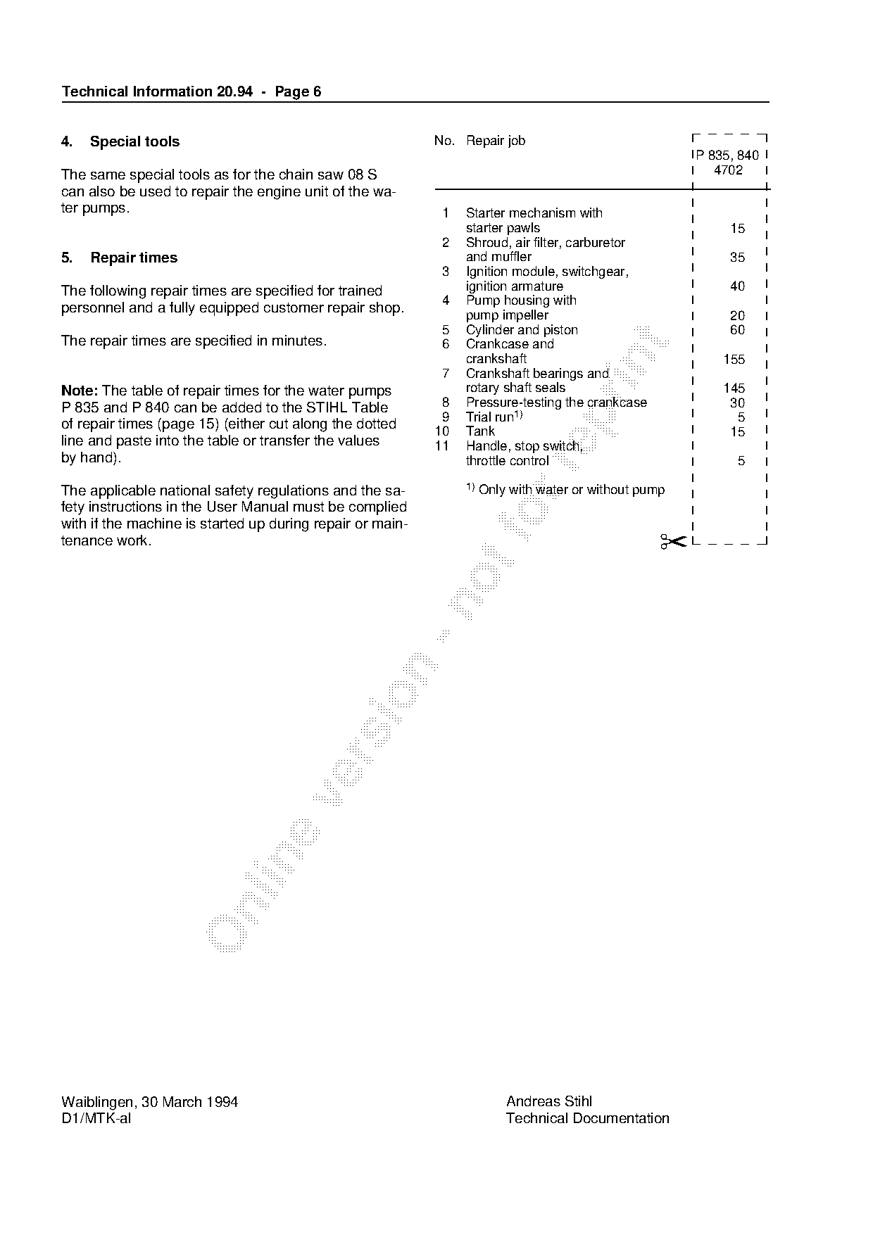
The same special tools as for the chain saw 08 S                                                        4702
can also be used to repair the engine unit of the wa-
ter pumps.                                                  1   Starter mechanism with
                                                                starter pawls                             15
                                                            2   Shroud, air filter, carburetor
5.   Repair times                                               and muffler                               35
                                                            3   Ignition module, switchgear,
The following repair times are specified for trained            ignition armature                         40
                                                            4   Pump housing with
personnel and a fully equipped customer repair shop.            pump impeller                             20
                                                            5   Cylinder and piston                       60
The repair times are specified in minutes.                  6   Crankcase and

                                                                crankshaft

                                                                                                         155
                                                            7   Crankshaft bearings and
Note: The table of repair times for the water pumps             rotary shaft seals                       145
P 835 and P 840 can be added to the STIHL Table             8   Pressure-testing the crankcase            30

                                                            9   Trial run1)                                5
of repair times (page 15) (either cut along the dotted     10   Tank                                      15
line and paste into the table or transfer the values       11   Handle, stop switch,
by hand).                                                       throttle control                           5

                                                                1) Only with water or without pump
The applicable national safety regulations and the sa-
fety instructions in the User Manual must be complied
with if the machine is started up during repair or main-           fo
tenance work.                                                                                    ✂

Waiblingen, 30 March 1994                                             Andreas Stihl
D1/MTK-al                                                             Technical Documentation
Most of these PDFs embed fonts with a shifted character map, so the text above was recovered rather than copied — read it as a faithful but imperfect transcription, and treat the page image above each block as the authority where the two disagree — the figures exist only there, because they are vector drawings that text extraction cannot keep.