Technical Information · issue 24 of 1994
New Edger FC 44
IssueTI 24/1994
Full text
Page 1 of 8
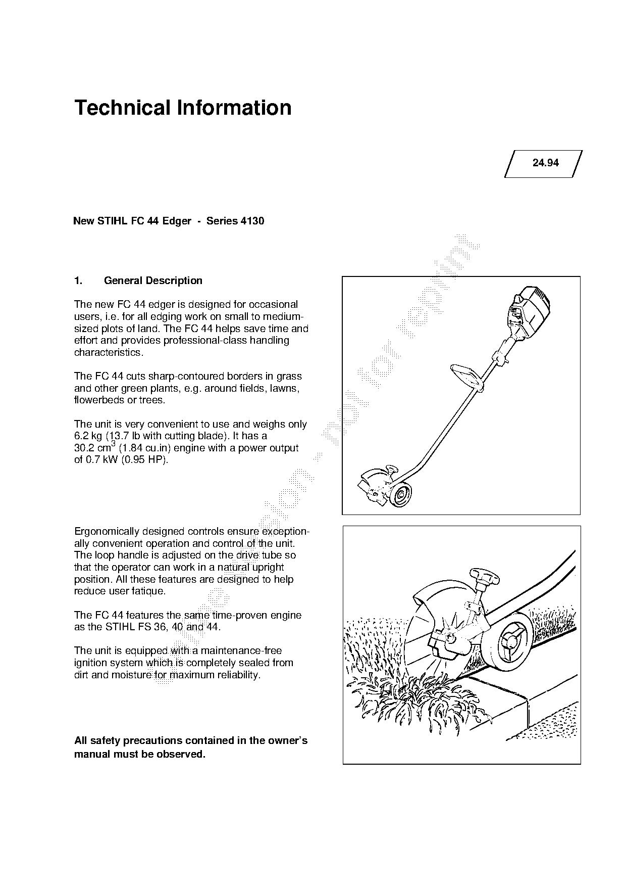
Text of page 1 — search, copy, screen readers
Technical Information

                                                                    24.94

New STIHL FC 44 Edger - Series 4130

1.    General Description

The new FC 44 edger is designed for occasional
users, i.e. for all edging work on small to medium-
sized plots of land. The FC 44 helps save time and

effort and provides professional-class handling
characteristics.

The FC 44 cuts sharp-contoured borders in grass
and other green plants, e.g. around fields, lawns,
flowerbeds or trees.

The unit is very convenient to use and weighs only

6.2 kg (13.7 lb with cutting blade). It has a
30.2 cm3 (1.84 cu.in) engine with a power output
of 0.7 kW (0.95 HP).

Ergonomically designed controls ensure exception-
ally convenient operation and control of the unit.

The loop handle is adjusted on the drive tube so
that the operator can work in a natural upright

position. All these features are designed to help
reduce user fatique.

The FC 44 features the same time-proven engine

as the STIHL FS 36, 40 and 44.

The unit is equipped with a maintenance-free

ignition system which is completely sealed from
dirt and moisture for maximum reliability.

All safety precautions contained in the owner’s
manual must be observed.
Page 2 of 8
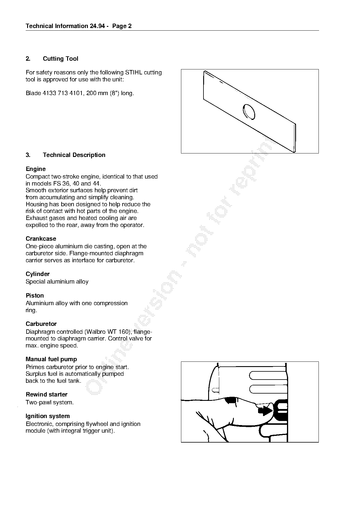
Text of page 2 — search, copy, screen readers
Technical Information 24.94 - Page 2

2.    Cutting Tool

For safety reasons only the following STIHL cutting
tool is approved for use with the unit:

Blade 4133 713 4101, 200 mm (8") long.

3.    Technical Description

Engine

Compact two-stroke engine, identical to that used
in models FS 36, 40 and 44.
Smooth exterior surfaces help prevent dirt

from accumulating and simplify cleaning.
Housing has been designed to help reduce the
risk of contact with hot parts of the engine.
Exhaust gases and heated cooling air are
expelled to the rear, away from the operator.
Crankcase
One-piece aluminium die casting, open at the

carburetor side. Flange-mounted diaphragm
carrier serves as interface for carburetor.

Cylinder

Special aluminium alloy

Piston
Aluminium alloy with one compression
ring.

Carburetor

Diaphragm controlled (Walbro WT 160), flange-
mounted to diaphragm carrier. Control valve for
max. engine speed.

Manual fuel pump
Primes carburetor prior to engine start.
Surplus fuel is automatically pumped

back to the fuel tank.

Rewind starter
Two-pawl system.

Ignition system
Electronic, comprising flywheel and ignition
module (with integral trigger unit).
Page 3 of 8
Text of page 3 — search, copy, screen readers
Technical Information 24.94 - Page 3

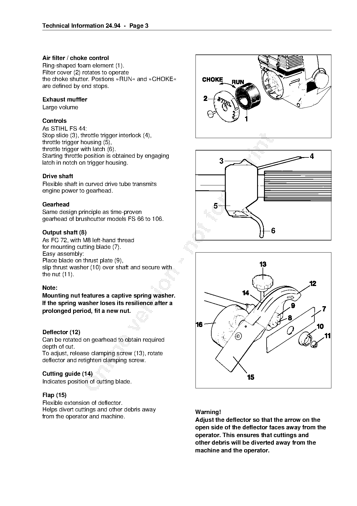
Air filter / choke control
Ring-shaped foam element (1).
Filter cover (2) rotates to operate
the choke shutter. Postions »RUN« and »CHOKE«
are defined by end stops.

Exhaust muffler
Large volume

Controls
As STIHL FS 44:
Stop slide (3), throttle trigger interlock (4),

throttle trigger housing (5),

throttle trigger with latch (6).
Starting throttle position is obtained by engaging                                           4
latch in notch on trigger housing.                             3

Drive shaft
Flexible shaft in curved drive tube transmits

engine power to gearhead.

Gearhead                                                   5
Same design principle as time-proven
gearhead of brushcutter models FS 66 to 106.
                                                                               6
Output shaft (8)
As FC 72, with M8 left-hand thread
for mounting cutting blade (7).

Easy assembly:
Place blade on thrust plate (9),
slip thrust washer (10) over shaft and secure with

the nut (11).

Note:
Mounting nut features a captive spring washer.
If the spring washer loses its resilience after a

prolonged period, fit a new nut.

Deflector (12)
Can be rotated on gearhead to obtain required
depth of cut.

To adjust, release clamping screw (13), rotate
deflector and retighten clamping screw.

Cutting guide (14)
Indicates position of cutting blade.

Flap (15)
Flexible extension of deflector.
Helps divert cuttings and other debris away          Warning!
from the operator and machine.
                                                     Adjust the deflector so that the arrow on the
                                                     open side of the deflector faces away from the
                                                     operator. This ensures that cuttings and
                                                     other debris will be diverted away from the
                                                     machine and the operator.
Page 4 of 8
Text of page 4 — search, copy, screen readers
Technical Information 24.94 - Page 4

Depth wheel (16)
Helps maintain the required depth of cut and
supports part of the edger’s weight.
Can be mounted on either side of the deflector.
Position of rubber flap must then be changed
to match.

4.     Specifications

4.1    Powerhead

4.1.1 Engine

Single cylinder two-stroke engine with special impregnated bore
Displacement:                          30.2 cm3 (1.84 cu.in)

Bore:                                  34.8 mm (1.37 in)
Stroke:                                31.8 mm (1.25 in)
Engine power to ISO 8893:              0.7 kW (0.95 HP)

Max. permissible engine speed
without cutting blade
(cut-off speed):                      9,300 rpm (+/- 700 rpm)

Bearings:                             Crankshaft supported in heavy-duty ball bearings;
                                      big-end and small-end bearings are needle
                                      cages

Rewind starter:                       Two pawl system
Spare travel on

                                      1
rewind spring:                         /4 ... 1 3/4 turns of rope rotor
Pawl/pin clearance:                   0.05 ... 0.4 mm (0.0020 - 0.016 in)
Starter rope
- Diameter:                           3.5 mm (0.14 in)

- Length:                             850 mm (33.5 in)

Silencing:                            Intake air silencing and efficient
                                      exhaust muffler

4.1.2 Fuel system

Carburetor:                           All position diaphragm carburetor
                                      with integral fuel pump
Air filter:                           Foam element
Fuel capacity:                        0.51 L (1.1 US pt)
Fuel mixture:                         Brand-name regular grade gasoline (unleaded or
                                      leaded) and STIHL two-stroke engine oil
Mix ratio:                            50:1 with STIHL 1:50 engine oil
                                      25:1 with other branded two-stroke engine oils
Page 5 of 8
Text of page 5 — search, copy, screen readers
Technical Information 24.94 - Page 5

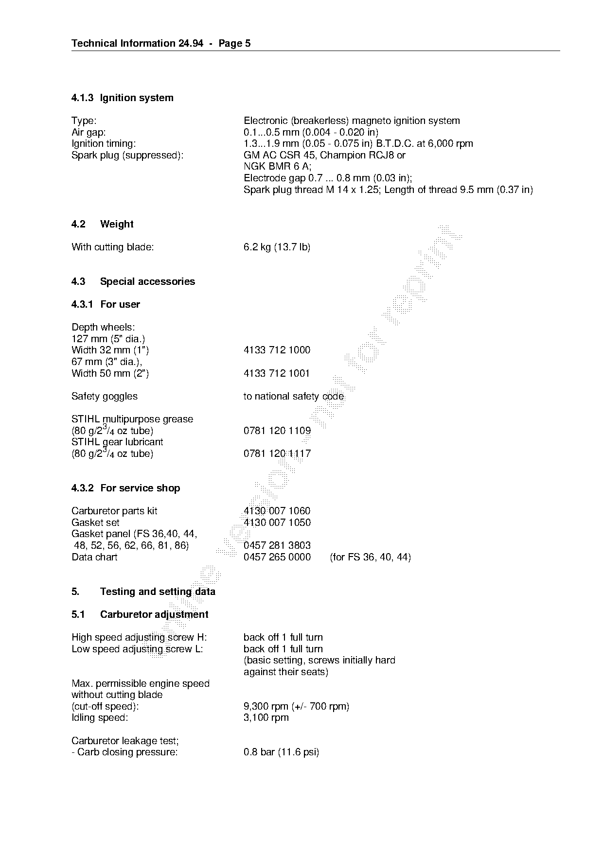
4.1.3 Ignition system

Type:                             Electronic (breakerless) magneto ignition system
Air gap:                          0.1...0.5 mm (0.004 - 0.020 in)
Ignition timing:                  1.3...1.9 mm (0.05 - 0.075 in) B.T.D.C. at 6,000 rpm
Spark plug (suppressed):          GM AC CSR 45, Champion RCJ8 or
                                  NGK BMR 6 A;
                                  Electrode gap 0.7 ... 0.8 mm (0.03 in);
                                  Spark plug thread M 14 x 1.25; Length of thread 9.5 mm (0.37 in)

4.2   Weight

With cutting blade:               6.2 kg (13.7 lb)

4.3   Special accessories

4.3.1 For user

Depth wheels:
127 mm (5" dia.)
Width 32 mm (1")                  4133 712 1000
67 mm (3" dia.),
Width 50 mm (2")                  4133 712 1001
Safety goggles                    to national safety code

STIHL multipurpose grease
(80 g/23/4 oz tube)               0781 120 1109
STIHL gear lubricant
(80 g/23/4 oz tube)               0781 120 1117

4.3.2 For service shop

Carburetor parts kit              4130 007 1060
Gasket set                        4130 007 1050

Gasket panel (FS 36,40, 44,
48, 52, 56, 62, 66, 81, 86)       0457 281 3803

Data chart                        0457 265 0000        (for FS 36, 40, 44)

5.    Testing and setting data

5.1   Carburetor adjustment

High speed adjusting screw H:     back off 1 full turn
Low speed adjusting screw L:      back off 1 full turn
                                  (basic setting, screws initially hard
                                  against their seats)
Max. permissible engine speed
without cutting blade
(cut-off speed):                  9,300 rpm (+/- 700 rpm)
Idling speed:                     3,100 rpm

Carburetor leakage test;
- Carb closing pressure:          0.8 bar (11.6 psi)
Page 6 of 8
Text of page 6 — search, copy, screen readers
Technical Information 24.94 - Page 6

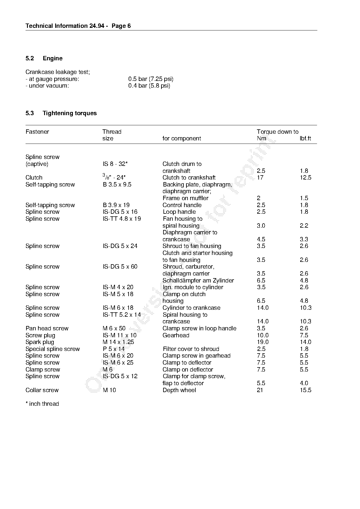
5.2   Engine

Crankcase leakage test;
- at gauge pressure:                    0.5 bar (7.25 psi)
- under vacuum:                         0.4 bar (5.8 psi)

5.3   Tightening torques

Fastener                   Thread                                                  Torque down to
                           size                      for component                 Nm             lbf.ft

Spline screw
(captive)                  IS 8 - 32*                Clutch drum to
                                                     crankshaft                    2.5             1.8

                           3
Clutch                      /8" - 24*                Clutch to crankshaft          17              12.5
Self-tapping screw         B 3.5 x 9.5               Backing plate, diaphragm,
                                                     diaphragm carrier;

                                                     Frame on muffler              2               1.5
Self-tapping screw         B 3.9 x 19                Control handle                2.5             1.8
Spline screw
Spline screw
                           IS-DG 5 x 16
                           IS-TT 4.8 x 19
                                                     Loop handle  fo
                                                     Fan housing to
                                                                                   2.5             1.8

                                                     spiral housing                3.0             2.2
                                                     Diaphragm carrier to
                                                     crankcase                     4.5             3.3
Spline screw               IS-DG 5 x 24              Shroud to fan housing         3.5             2.6

                                                     Clutch and starter housing
                                                     to fan housing                3.5             2.6
Spline screw               IS-DG 5 x 60              Shroud, carburetor,
                                                     diaphragm carrier             3.5             2.6

                                                     Schalldämpfer am Zylinder     6.5             4.8

Spline screw               IS-M 4 x 20               Ign. module to cylinder       3.5             2.6
Spline screw               IS-M 5 x 18               Clamp on clutch
                                                     housing                       6.5             4.8
Spline screw               IS-M 6 x 18               Cylinder to crankcase         14.0            10.3

Spline screw               IS-TT 5.2 x 14            Spiral housing to
                                                     crankcase                     14.0            10.3
Pan head screw             M 6 x 50                  Clamp screw in loop handle    3.5             2.6

Screw plug                 IS-M 11 x 10              Gearhead                      10.0            7.5
Spark plug                 M 14 x 1.25                                             19.0            14.0
Special spline screw       P 5 x 14                  Filter cover to shroud        2.5             1.8

Spline screw               IS-M 6 x 20               Clamp screw in gearhead       7.5             5.5
Spline screw               IS-M 6 x 25               Clamp to deflector            7.5             5.5
Clamp screw                M6                        Clamp on deflector            7.5             5.5

Spline screw               IS-DG 5 x 12              Clamp for clamp screw,
                                                     flap to deflector             5.5             4.0
Collar screw               M 10                      Depth wheel                   21              15.5

* inch thread
Page 7 of 8
Text of page 7 — search, copy, screen readers
Technical Information 24.94 - Page 7

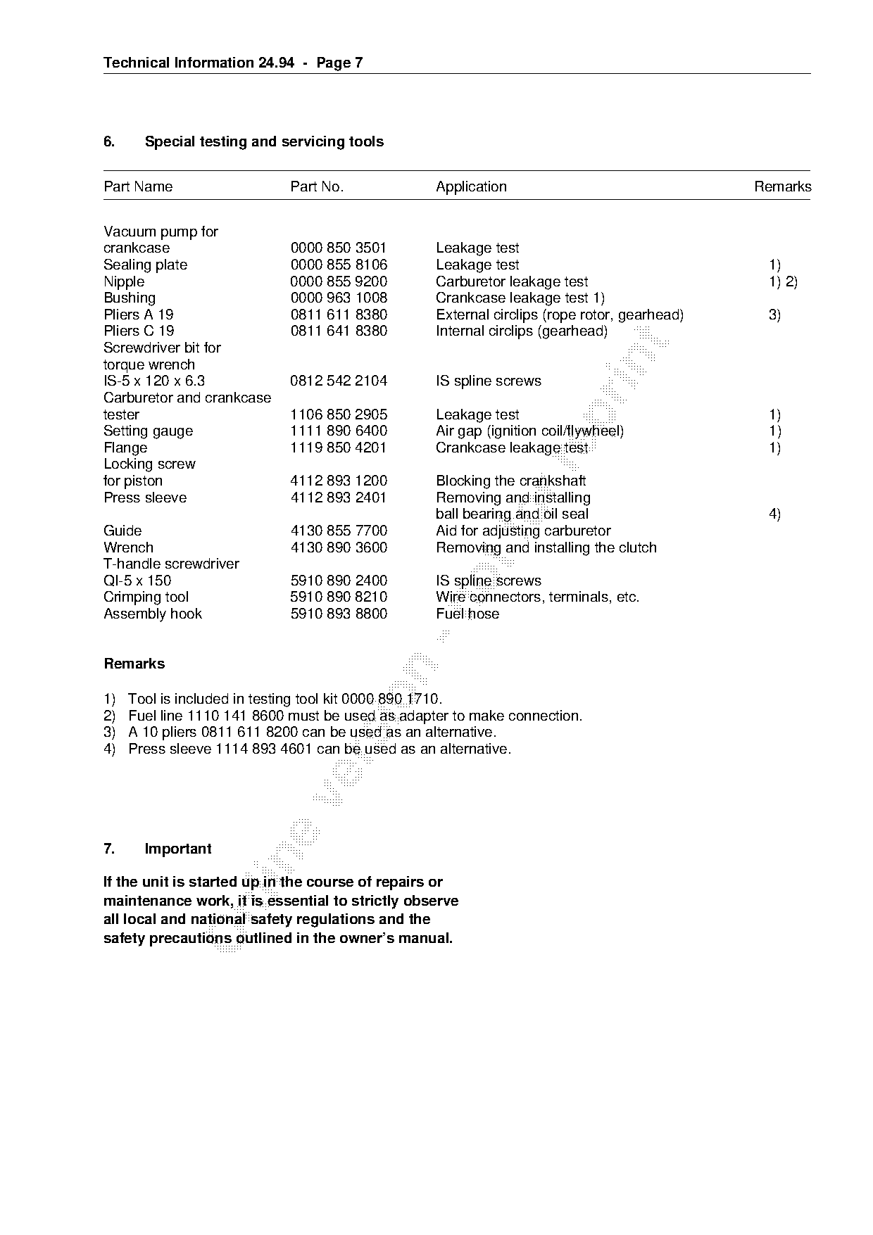
6.     Special testing and servicing tools

Part Name                   Part No.              Application                                Remarks

Vacuum pump for
crankcase                   0000 850 3501         Leakage test
Sealing plate               0000 855 8106         Leakage test                                1)
Nipple                      0000 855 9200         Carburetor leakage test                     1) 2)
Bushing                     0000 963 1008         Crankcase leakage test 1)
Pliers A 19                 0811 611 8380         External circlips (rope rotor, gearhead)    3)
Pliers C 19                 0811 641 8380         Internal circlips (gearhead)

Screwdriver bit for

torque wrench
IS-5 x 120 x 6.3            0812 542 2104         IS spline screws
Carburetor and crankcase
tester                      1106 850 2905         Leakage test                                1)

Setting gauge               1111 890 6400         Air gap (ignition coil/flywheel)            1)
Flange                      1119 850 4201         Crankcase leakage test                      1)
Locking screw

for piston                  4112 893 1200         Blocking the crankshaft
Press sleeve                4112 893 2401         Removing and installing

Guide                       4130 855 7700
                                                  ball bearing and oil seal
                                                  Aid for adjusting carburetor
                                                                                              4)

Wrench                      4130 890 3600         Removing and installing the clutch
T-handle screwdriver
QI-5 x 150                  5910 890 2400         IS spline screws
Crimping tool               5910 890 8210         Wire connectors, terminals, etc.

Assembly hook               5910 893 8800         Fuel hose

Remarks

1)   Tool is included in testing tool kit 0000 890 1710.
2)   Fuel line 1110 141 8600 must be used as adapter to make connection.
3)   A 10 pliers 0811 611 8200 can be used as an alternative.
4)   Press sleeve 1114 893 4601 can be used as an alternative.

7.     Important

If the unit is started up in the course of repairs or
maintenance work, it is essential to strictly observe

all local and national safety regulations and the
safety precautions outlined in the owner’s manual.
Page 8 of 8
Text of page 8 — search, copy, screen readers
Technical Information 24.94 - Page 8

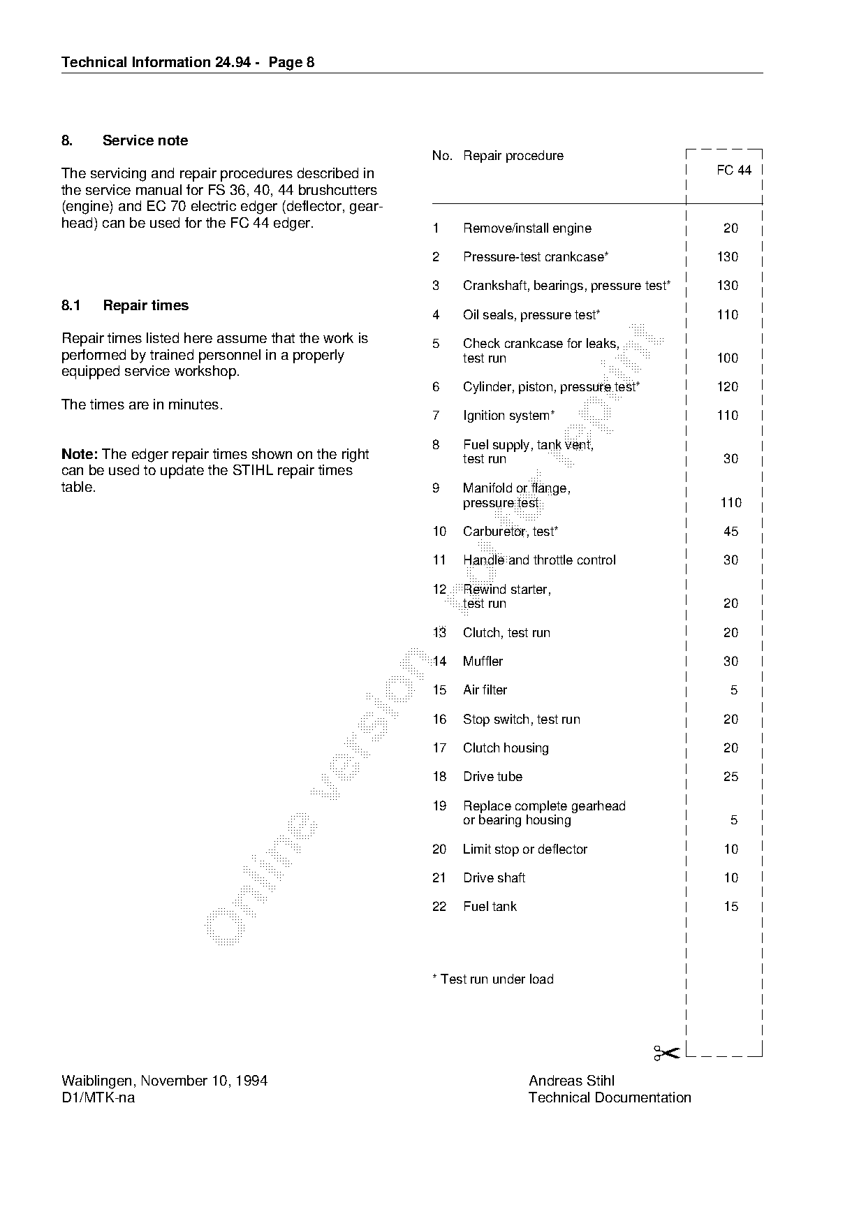
8.    Service note
                                                       No. Repair procedure
The servicing and repair procedures described in                                                    FC 44
the service manual for FS 36, 40, 44 brushcutters
(engine) and EC 70 electric edger (deflector, gear-
head) can be used for the FC 44 edger.                 1    Remove/install engine                    20

                                                       2    Pressure-test crankcase*                130

                                                       3    Crankshaft, bearings, pressure test*    130
8.1   Repair times
                                                       4    Oil seals, pressure test*               110
Repair times listed here assume that the work is

                                                       5    Check crankcase for leaks,
performed by trained personnel in a properly

                                                            test run                                100
equipped service workshop.
                                                       6    Cylinder, piston, pressure test*        120
The times are in minutes.

                                                       7    Ignition system*                        110

                                                       8    Fuel supply, tank vent,
Note: The edger repair times shown on the right             test run                                 30

can be used to update the STIHL repair times
table.                                                 9    Manifold or flange,
                                                            pressure test                           110

                                                       10
                                                            Carburetor, test*                        45
                                                       11   Handle and throttle control              30

                                                       12   Rewind starter,

                                                            test run                                 20

                                                       13   Clutch, test run                         20

                                                       14   Muffler                                  30

                                                       15   Air filter                                5

                                                       16   Stop switch, test run                    20

                                                       17   Clutch housing                           20

                                                       18   Drive tube                               25

                                                       19   Replace complete gearhead
                                                            or bearing housing                        5

                                                       20   Limit stop or deflector                  10

                                                       21   Drive shaft                              10

                                                       22   Fuel tank                                15

                                                       * Test run under load

                                                                                               ✂
Waiblingen, November 10, 1994                                             Andreas Stihl
D1/MTK-na                                                                 Technical Documentation
Most of these PDFs embed fonts with a shifted character map, so the text above was recovered rather than copied — read it as a faithful but imperfect transcription, and treat the page image above each block as the authority where the two disagree — the figures exist only there, because they are vector drawings that text extraction cannot keep.