Technical Information · issue 25 of 1994
Fuel hose/grommet; muffler
Models HS 72, 74 and 76 will come with new crank-
IssueTI 25/1994
From serial 29 943 802
Part changes (4)
| Was | Becomes | What the bulletin says |
|---|---|---|
| 4226 350 0405 | 9022 341 1010 | 1 Fuel tank The IS-M 5 x 20 spline screw (9022 341 1020) previously used to mount the fuel tank has been Fuel tank 4226 350 0405 will be supplied as deleted and replaced by an IS-M 5 x18 spline a spare part instead of the original tank screw (9022 341 1010). |
| 4133 350 0501 | 4226 350 0501 | Fuel filler cap 4133 350 0501 will be replaced by 3 the version 4226 350 0501. |
| 9216 263 0700 | 9220 260 0701 | The M5 locknut 9216 263 0700 will be replaced by locknut 9220 260 0701 to further enhance reliability. |
| 4133 893 1300 | 4133 893 1301 | 2 Wrench for clutch (special tool) SW The existing wrench 4133 893 1300 (3) has been SW replaced by the new version 4133 893 1301 (4) in connection with the change in the shape of the clutch carrier (see 9. |
Full text
Page 1 of 8
Text of page 1 — search, copy, screen readers
Technical Information

                                                                                25.94

STIHL HS 72, 74, 76 Hedge Trimmers - Series 4226

Contents

 1. Muffler (cover plate with asymmetric hole pattern)

 2. Fuel hose (tank entry with grommet)
 3. Hand guard/handle molding (different mounting screw)
 4. Cutter bar assembly 1000 ES (new cutting length)

 5. Cutter guard for HS 76 (no longer standard equipment)
 6. Cutter bar (locknut)
 7. Crankcase (new shape)
 8. Carburetor (pump diaphragm)
 9. Clutch (carrier, wrench, clutch shoes, springs)
10. Catcher plate (option)

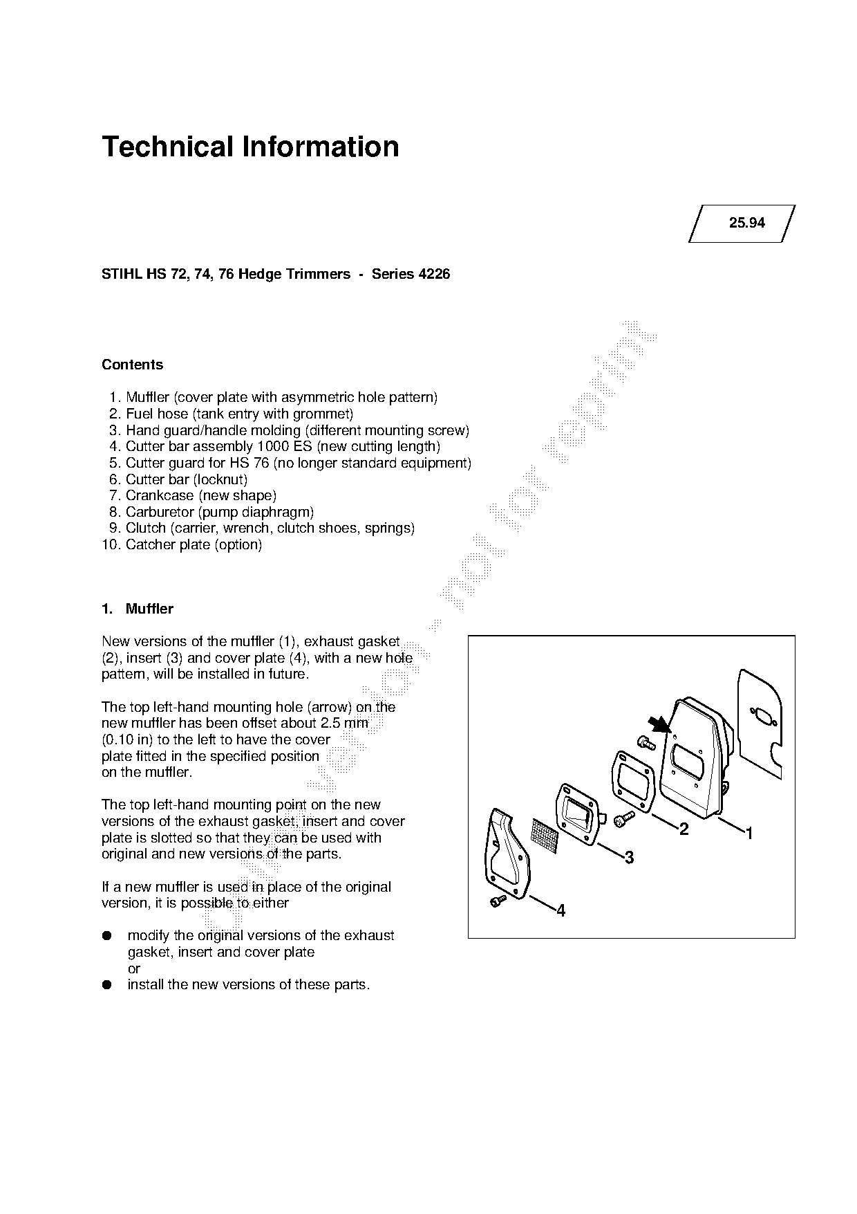
1. Muffler

New versions of the muffler (1), exhaust gasket

(2), insert (3) and cover plate (4), with a new hole
pattern, will be installed in future.

The top left-hand mounting hole (arrow) on the
new muffler has been offset about 2.5 mm
(0.10 in) to the left to have the cover

plate fitted in the specified position
on the muffler.

The top left-hand mounting point on the new
versions of the exhaust gasket, insert and cover
plate is slotted so that they can be used with
                                                                            2     1

original and new versions of the parts.                                3
If a new muffler is used in place of the original

version, it is possible to either
                                                                 4
●   modify the original versions of the exhaust
    gasket, insert and cover plate
●   install the new versions of these parts.
Page 2 of 8
Text of page 2 — search, copy, screen readers
Technical Information 25.94 - Page 2

The exhaust gasket (2) is also included in the                    because the fuel tank could in certain
gasket set. Only the new version of the gasket                    circumstances be damaged by hot exhaust gases.
set 4226 007 1051 (with new exhaust gasket) is                    In order to reduce risk of fire and burns caused by
available from the factory.                                       hot exhaust gases follow these instructions.

Warning!

When assembling the original versions of the
exhaust muffler (1), insert (3) and cover (4), note
that

●    the outlet on the cover plate must point in the
     direction of the cutter bar

●    the short tube in the insert must point towards

     the fan housing

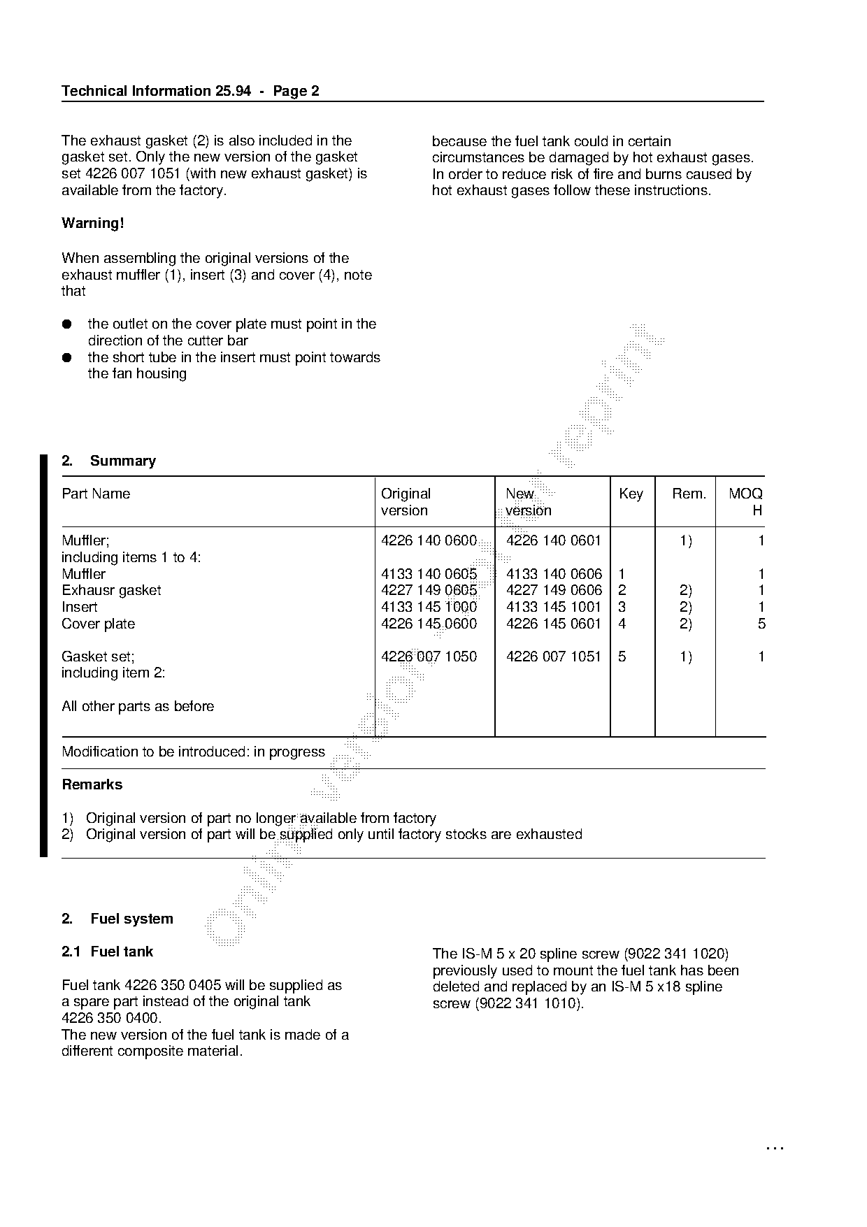
2.   Summary

Part Name                                              Original              New               Key     Rem.     MOQ

Muffler;
                                                       version

                                                       4226 140 0600
                                                                          fo version

                                                                             4226 140 0601               1)
                                                                                                                  H

                                                                                                                        1
including items 1 to 4:
Muffler                                                4133 140 0605         4133 140 0606     1                        1
Exhausr gasket                                         4227 149 0605         4227 149 0606     2         2)             1

Insert                                                 4133 145 1000         4133 145 1001     3         2)             1
Cover plate                                            4226 145 0600         4226 145 0601     4         2)             5

Gasket set;                                            4226 007 1050         4226 007 1051     5         1)             1

including item 2:

All other parts as before

Modification to be introduced: in progress

Remarks

1) Original version of part no longer available from factory
2) Original version of part will be supplied only until factory stocks are exhausted

2.   Fuel system

2.1 Fuel tank                                                     The IS-M 5 x 20 spline screw (9022 341 1020)
                                                                  previously used to mount the fuel tank has been
Fuel tank 4226 350 0405 will be supplied as                       deleted and replaced by an IS-M 5 x18 spline
a spare part instead of the original tank                         screw (9022 341 1010).
4226 350 0400.
The new version of the fuel tank is made of a
different composite material.

                                                                                                                            ...
Page 3 of 8
Text of page 3 — search, copy, screen readers
Technical Information 25.94 - Page 3

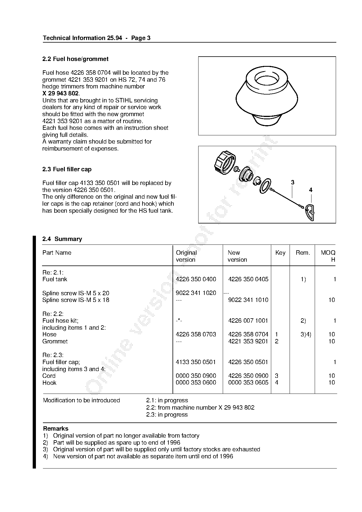
2.2 Fuel hose/grommet

Fuel hose 4226 358 0704 will be located by the
grommet 4221 353 9201 on HS 72, 74 and 76
hedge trimmers from machine number
X 29 943 802.
Units that are brought in to STIHL servicing
dealers for any kind of repair or service work
should be fitted with the new grommet
4221 353 9201 as a matter of routine.
Each fuel hose comes with an instruction sheet
giving full details.
A warranty claim should be submitted for

reimbursement of expenses.

2.3 Fuel filler cap

Fuel filler cap 4133 350 0501 will be replaced by                                             3
the version 4226 350 0501.                                                                              4

The only difference on the original and new fuel fil-
ler caps is the cap retainer (cord and hook) which
has been specially designed for the HS fuel tank.
2.4 Summary

Part Name                                           Original           New              Key       Rem.      MOQ
                                                    version            version                                H

Re: 2.1:

Fuel tank                                           4226 350 0400      4226 350 0405               1)         1

Spline screw IS-M 5 x 20                            9022 341 1020    ---
Spline screw IS-M 5 x 18                            ---                 9022 341 1010                        10

Re: 2.2:

Fuel hose kit;                                      -*-                4226 007 1001               2)         1
including items 1 and 2:

Hose                                                4226 358 0703      4226 358 0704    1          3)4)      10
Grommet                                             ---                4221 353 9201    2                    10

Re: 2.3:

Fuel filler cap;                                    4133 350 0501      4226 350 0501                          1
including items 3 and 4:
Cord                                                0000 350 0900      4226 350 0900    3                    10

Hook                                                0000 353 0600      0000 353 0605    4                    10

Modification to be introduced           2.1: in progress
                                        2.2: from machine number X 29 943 802
                                        2.3: in progress

Remarks
1) Original version of part no longer available from factory
2) Part will be supplied as spare up to end of 1996
3) Original version of part will be supplied only until factory stocks are exhausted
4) New version of part not available as separate item until end of 1996
Page 4 of 8
Text of page 4 — search, copy, screen readers
Technical Information 25.94 - Page 4

3. Handle molding (HS 72, 74 only)

In future the handle moldings of models HS 72 and
HS 74 will be secured with IS-P 4 x 19 Plastoform
spline screws instead of the IS-BZ 4 x 19 self-tap-
ping screws used up to now.

Summary

Part Name                                         Original          New               Key   Rem.   MOQ
                                                  version           version                          H

Self-tapping screw IS-BZ 4 x 19                   9074 478 3065    ---                       1)
Spline screw IS- P 4 x 19                         ---                 9074 478 3075                 10

Modification to be introduced: in progress

Remarks

1) Part remains available as spare for other models

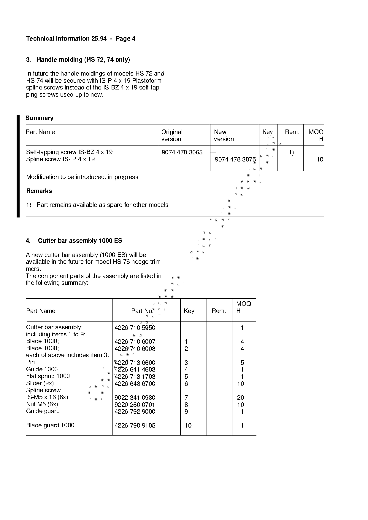
4.   Cutter bar assembly 1000 ES

A new cutter bar assembly (1000 ES) will be
available in the future for model HS 76 hedge trim-
mers.
The component parts of the assembly are listed in

the following summary:

                                                                              MOQ
Part Name                              Part No.              Key   Rem.       H

Cutter bar assembly;              4226 710 5950                               1
including items 1 to 9:

Blade 1000;                       4226 710 6007              1                4
Blade 1000;                       4226 710 6008              2                4
each of above includes item 3:

Pin                               4226 713 6600              3                 5
Guide 1000                        4226 641 4603              4                 1
Flat spring 1000                  4226 713 1703              5                 1

Slider (9x)                       4226 648 6700              6                10
Spline screw
IS-M5 x 16 (6x)                   9022 341 0980              7                20
Nut M5 (6x)                       9220 260 0701              8                10
Guide guard                       4226 792 9000              9                 1

Blade guard 1000                  4226 790 9105              10               1
Page 5 of 8
Text of page 5 — search, copy, screen readers
Technical Information 25.94 - Page 5

5. Cutter guard for HS 76

Cutter guard 4226 792 9105 has been deleted on all versions of the HS 76 to help increase cutting capacity.

6. Cutter bar (all versions)

The M5 locknut 9216 263 0700 will be replaced by locknut 9220 260 0701 to further enhance reliability. The
property class of the new locknut has been matched to that of the IS-M5 x 16 spline screw 9022 341 0980.

Summary

Part Name                                           Original           New              Key     Rem.   MOQ

                                                    version            version                           H

Locknut M5                                         9216 263 0700       9220 260 0701            1)        10

Modification to be introduced: in progress

Remarks
1) Original version of part remains available as spare for other models
7.   Crankcase

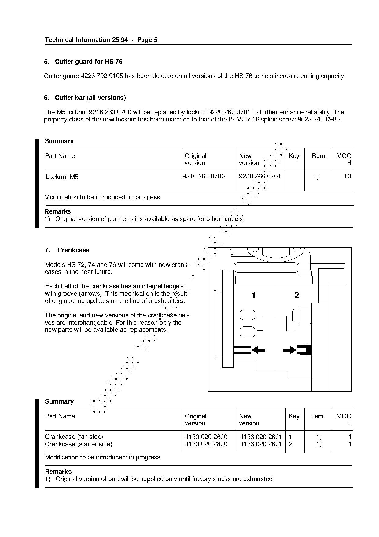
Models HS 72, 74 and 76 will come with new crank-
cases in the near future.

Each half of the crankcase has an integral ledge

with groove (arrows). This modification is the result                       1               2
of engineering updates on the line of brushcutters.

The original and new versions of the crankcase hal-
ves are interchangeable. For this reason only the

new parts will be available as replacements.

Summary

Part Name                                           Original           New              Key     Rem.   MOQ
                                                    version            version                           H

Crankcase (fan side)                                4133 020 2600       4133 020 2601   1        1)           1
Crankcase (starter side)                            4133 020 2800       4133 020 2801   2        1)           1

Modification to be introduced: in progress

Remarks
1) Original version of part will be supplied only until factory stocks are exhausted
Page 6 of 8
Text of page 6 — search, copy, screen readers
Technical Information 25.94 - Page 6

8. Carburetor/pump diaphragm

In order to standardize parts with other models, the
pump diaphragm 1120 121 4805 will be supplied
as a spare with immediate effect in place of pump
diaphragm 4133 121 4800.

This change also affects the carburetor parts
kit 4133 007 1060 which is supplied for shop
repairs.

Summary

Part Name                                          Original          New              Key   Rem.   MOQ
                                                   version           version                         H

Carburetor WT 264;                                 226 120 0600       4226 120 0600          1)
including :
Pump diaphragm                                     4133 121 4800      1120 121 4805   1      2)      1

Carburetor parts kit;                              4133 007 1060      4133 007 1060          1)
including item 1:

All other parts as before                                          fo
Modification to be introduced: in progress

Remarks

1) Unmodified version of part will be supplied until existing stocks are exhausted
2) Original version of part no longer available from factory

9.   Clutch

9.1 Carrier / clutch shoes

A modified carrier and clutch shoes will be
installed in future to help further optimize
clutch performance. Original and new versions

of the parts are not interchangeable. Only the
complete clutch assembly will be supplied as a
replacement to ensure easy exchangeability.

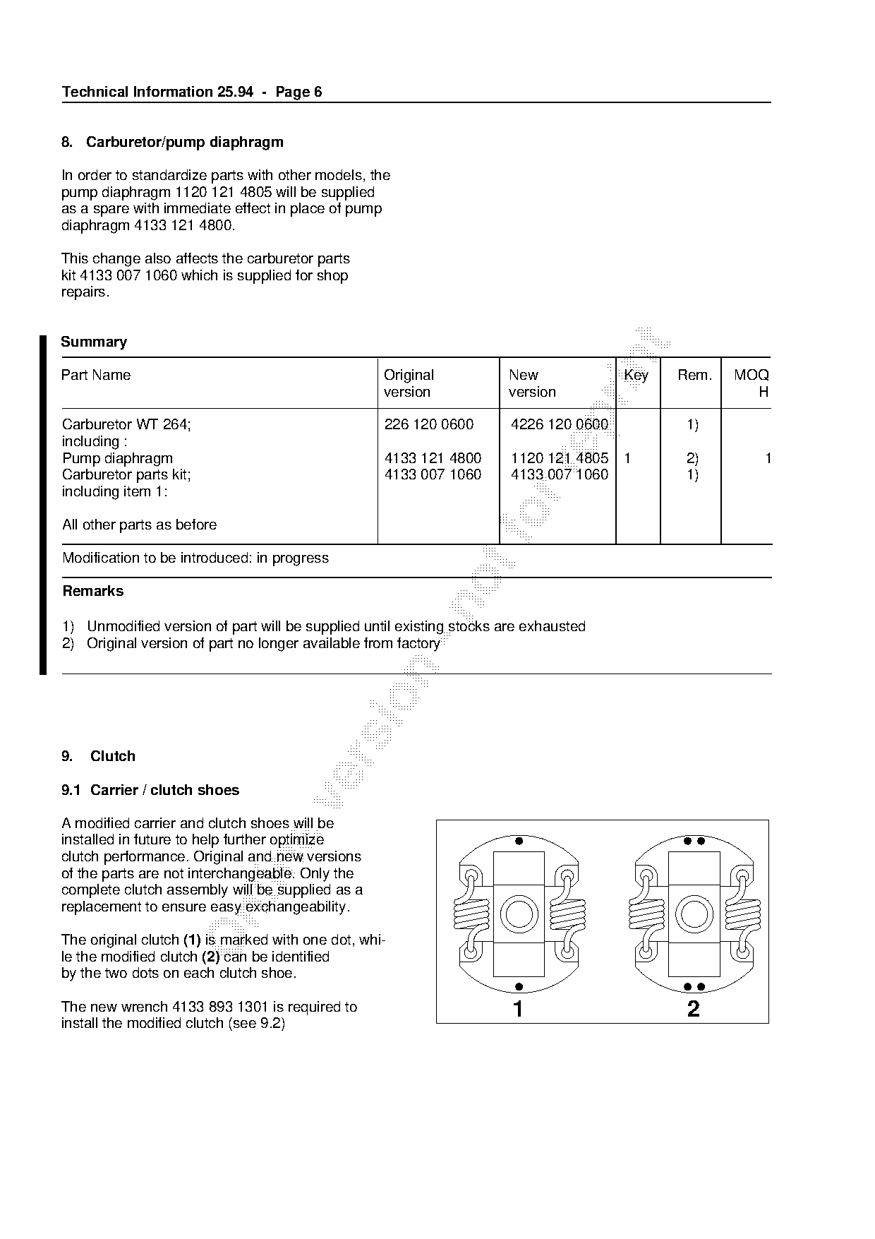
The original clutch (1) is marked with one dot, whi-
le the modified clutch (2) can be identified
by the two dots on each clutch shoe.

The new wrench 4133 893 1301 is required to                           1                      2
install the modified clutch (see 9.2)
Page 7 of 8
Text of page 7 — search, copy, screen readers
Technical Information 25.94 - Page 7

9.2 Wrench for clutch (special tool)
                                                                      SW
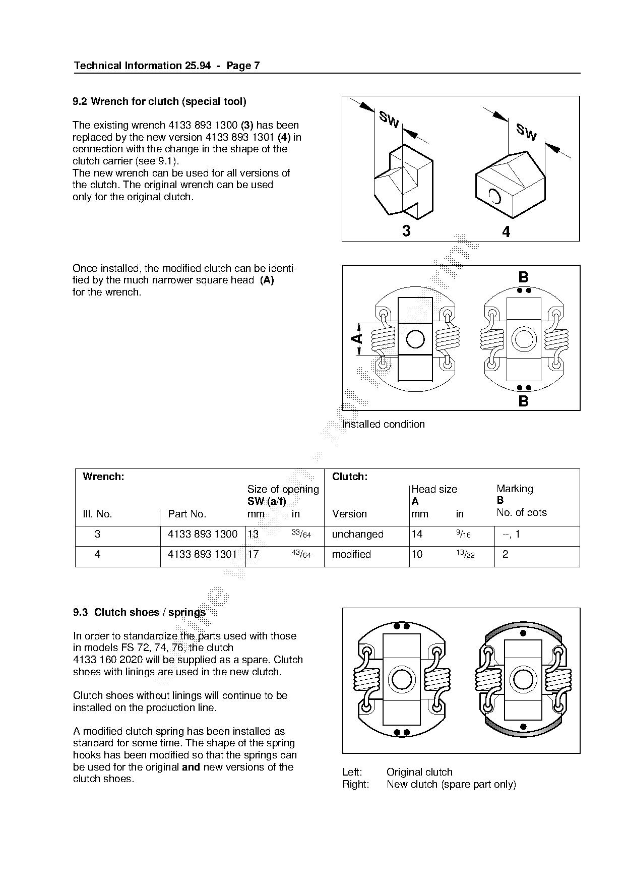
The existing wrench 4133 893 1300 (3) has been                                                       SW
replaced by the new version 4133 893 1301 (4) in
connection with the change in the shape of the
clutch carrier (see 9.1).
The new wrench can be used for all versions of
the clutch. The original wrench can be used
only for the original clutch.

                                                                           3                     4

Once installed, the modified clutch can be identi-
fied by the much narrower square head (A)                                                             B

for the wrench.

                                                              fo A
                                                                                                      B

                                                             Installed condition

  Wrench:                                                  Clutch:

                                       Size of opening                         Head size        Marking

                                       SW (a/f)                                A                B
  Ill. No.           Part No.          mm        in        Version             mm       in      No. of dots

     3               4133 893 1300 13              33/64   unchanged           14       9/16     --, 1

     4               4133 893 1301 17              43/64   modified            10       13/32    2

9.3 Clutch shoes / springs

In order to standardize the parts used with those
in models FS 72, 74, 76, the clutch

4133 160 2020 will be supplied as a spare. Clutch
shoes with linings are used in the new clutch.

Clutch shoes without linings will continue to be
installed on the production line.

A modified clutch spring has been installed as
standard for some time. The shape of the spring
hooks has been modified so that the springs can
be used for the original and new versions of the
                                                             Left:     Original clutch
clutch shoes.
                                                             Right:    New clutch (spare part only)
Page 8 of 8
Text of page 8 — search, copy, screen readers
Technical Information 25.94 - Page 8

9.4 Summary

Part Name                                           Original            New               Key    Rem.   MOQ
                                                    version             version                           H

zu 9.1:   Clutch                                    4133 160 2000       4133 160 2000     1, 2   1)
Re 9.2:   Wrench                                    4133 893 1300       4133 893 1301     3, 4   2)       1
Re 9.3:   Clutch;                                   4133 160 2000       4133 160 2020            2)       1
          including
          item 5 and 6:
          Clutch shoe (2x)                          -*-               -*-                 5      3)
          Clutch spring (2x)                        4133 162 7900     4133 162 7900       6      1)

Modification to be introduced:

for 9.1, 9.2, 9.3: in progress

Remarks

1) Unmodified version of part will be supplied until existing factory stocks are exhausted
2) Original version of part will be supplied from factory only as long as existing stocks last
3) Part is not available as separate item

10. Catcher plate (HS 76)
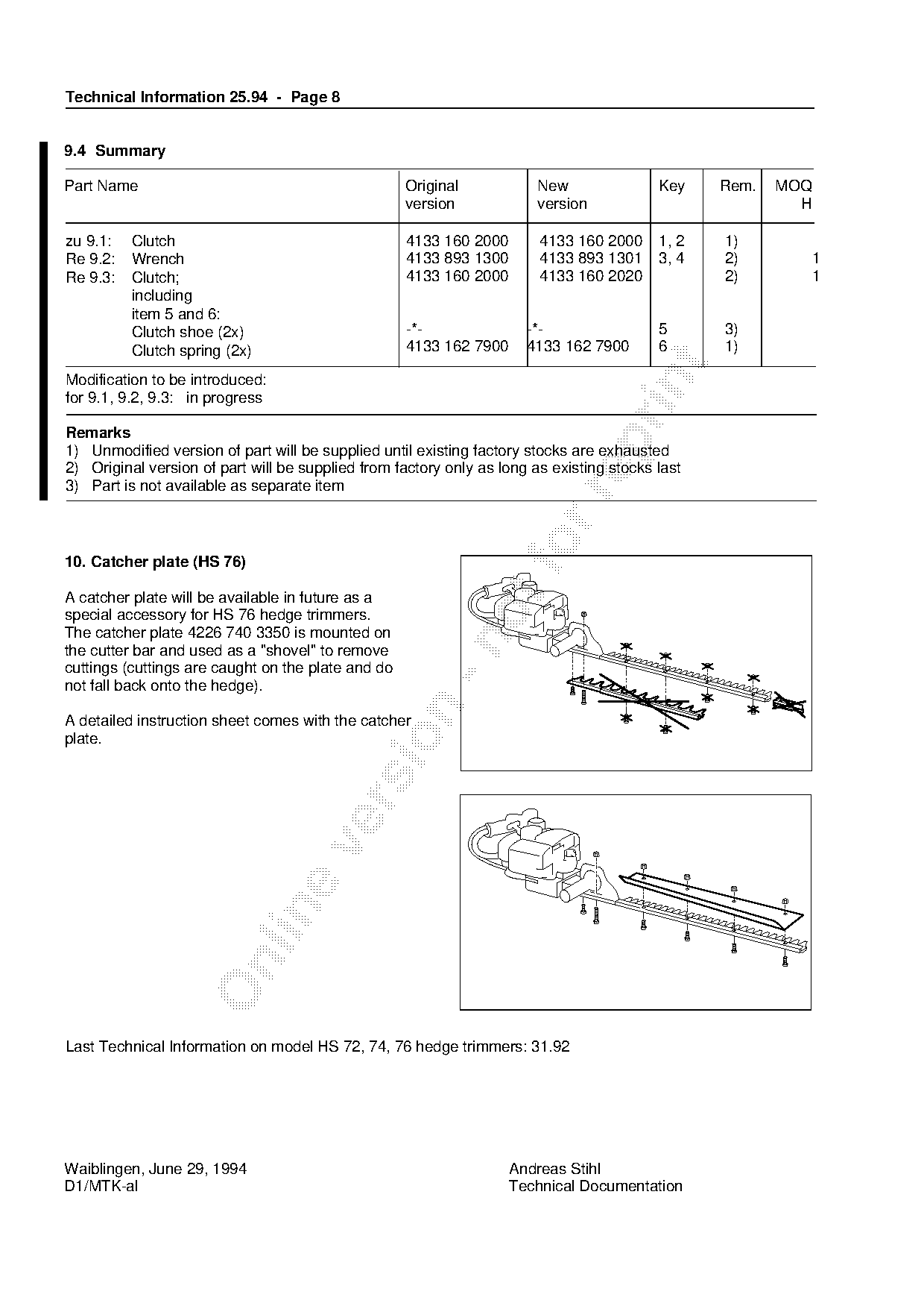
A catcher plate will be available in future as a
special accessory for HS 76 hedge trimmers.
The catcher plate 4226 740 3350 is mounted on

the cutter bar and used as a "shovel" to remove
cuttings (cuttings are caught on the plate and do
not fall back onto the hedge).

A detailed instruction sheet comes with the catcher

plate.

Last Technical Information on model HS 72, 74, 76 hedge trimmers: 31.92

Waiblingen, June 29, 1994                                           Andreas Stihl
D1/MTK-al                                                           Technical Documentation
Most of these PDFs embed fonts with a shifted character map, so the text above was recovered rather than copied — read it as a faithful but imperfect transcription, and treat the page image above each block as the authority where the two disagree — the figures exist only there, because they are vector drawings that text extraction cannot keep.