Technical Information · issue 29 of 1994
New replacement motors; automatic cut-in
IssueTI 29/1994
Full text
Page 1 of 7
Text of page 1 — search, copy, screen readers
Technical Information

                                                                                                       29.94

Vacuum STIHLSE 100 - Type 4709

            SE 200 - Type 4714

            SE 201 - Type 4714
            SE 202 - Type 4714

Summary

1. New replacement motors (protection class II, labelling of carbon brushes)
2. SE 100, 200, 202: retrofitting kit for automatic switch (function, installation, circuit diagram)
1. New replacement motors (protection class II)

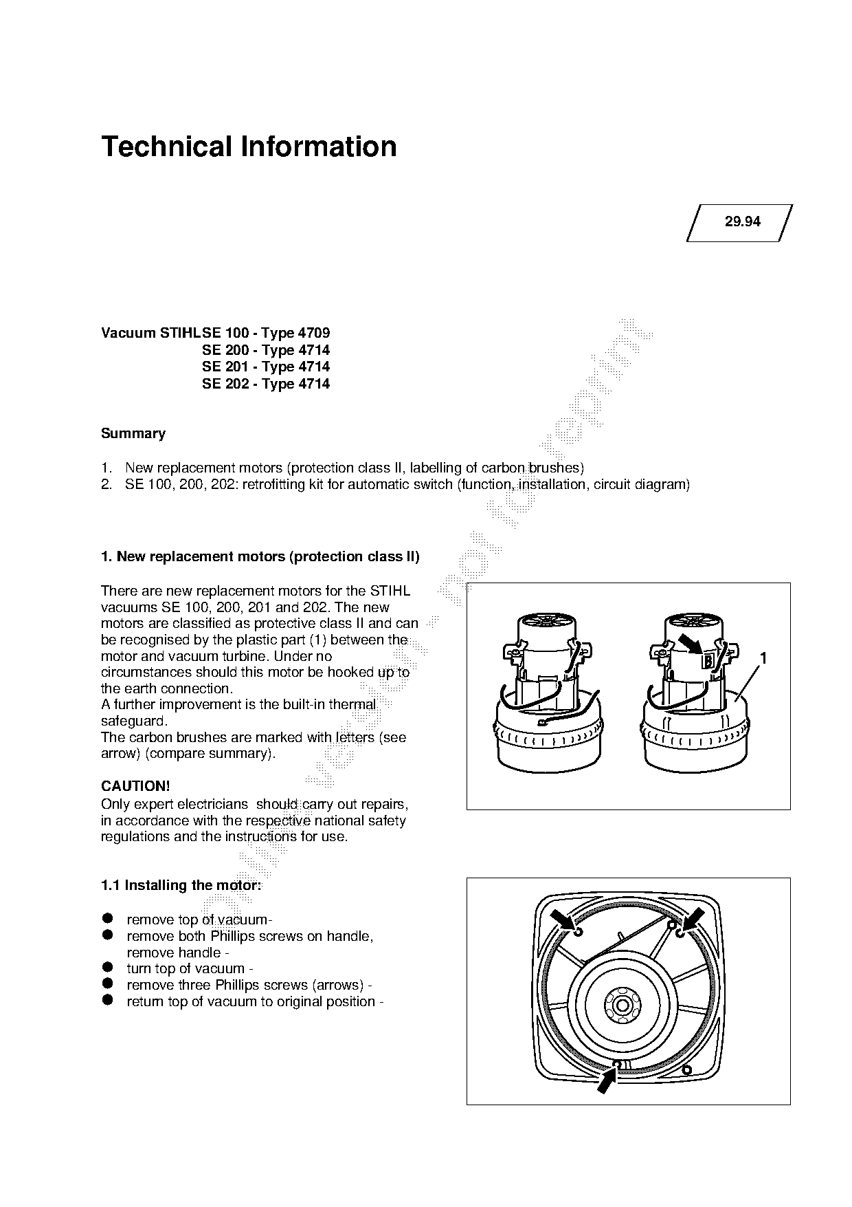
There are new replacement motors for the STIHL
vacuums SE 100, 200, 201 and 202. The new
motors are classified as protective class II and can
be recognised by the plastic part (1) between the

motor and vacuum turbine. Under no
circumstances should this motor be hooked up to

the earth connection.
A further improvement is the built-in thermal
safeguard.
The carbon brushes are marked with letters (see

arrow) (compare summary).

CAUTION!
Only expert electricians should carry out repairs,
in accordance with the respective national safety
regulations and the instructions for use.

1.1 Installing the motor:

• remove   top of vacuum-
• remove   both Phillips screws on handle,
  remove handle -
• turn top of vacuum -
• return topthree
  remove          Phillips screws (arrows) -
•             of vacuum   to original position -
Page 2 of 7
Text of page 2 — search, copy, screen readers
Technical Information 29.94 - Page 2

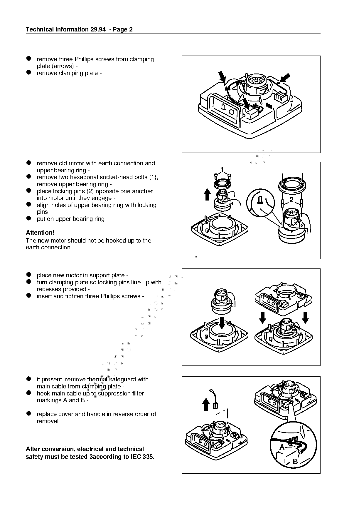
• remove   three Phillips screws from clamping
  plate (arrows) -
• remove clamping plate -

• remove   old motor with earth connection and
  upper bearing ring -
• remove

           two hexagonal socket-head bolts (1),
  remove upper bearing ring -
• place  locking pins (2) opposite one another

  into motor until they engage -
• align
  pins -
        holes of upper bearing ring with locking

• put on upper bearing ring -                             fo
Attention!
The new motor should not be hooked up to the
earth connection.

• place  new motor in support plate -
• turn

       clamping plate so locking pins line up with
  recesses provided -
• insert and tighten three Phillips screws -

• ifmain

     present, remove thermal safeguard with
         cable from clamping plate -
• hook   main cable up to suppression filter
  markings A and B -

• replace
  removal
          cover and handle in reverse order of

After conversion, electrical and technical
safety must be tested 3according to IEC 335.
Page 3 of 7
Text of page 3 — search, copy, screen readers
Technical Information 29.94 - Page 3

1.2 Summary
Designation                                       Original           New             Item   Rem.   MAM
                                                  Version            Version                         H

Electric motor 230 V/50 Hz;                          4709 600 0200   4709 600 0201          1)       1
containing Item 1
Carbon brushes (code letter H)                       4709 600 2700   4709 600 2701    1     2)       1
Electric motor 240 V/50 Hz                           4709 600 0205   4709 600 0206          1)       1
containing Item 2:
Carbon brushes (code letter B)                       4709 600 2700   4709 600 2702    2     2)       1
Suppression capacitor                                4709 605 1200   4709 605 1201          2)       1
Suppression capacitor (S/N/SF/GB 120 V)              4709 605 1205   4709 605 1206          2)       1

modification to be introduced: in progress

Remarks

1) part of original model no longer available ex factory
2) part of original model still available

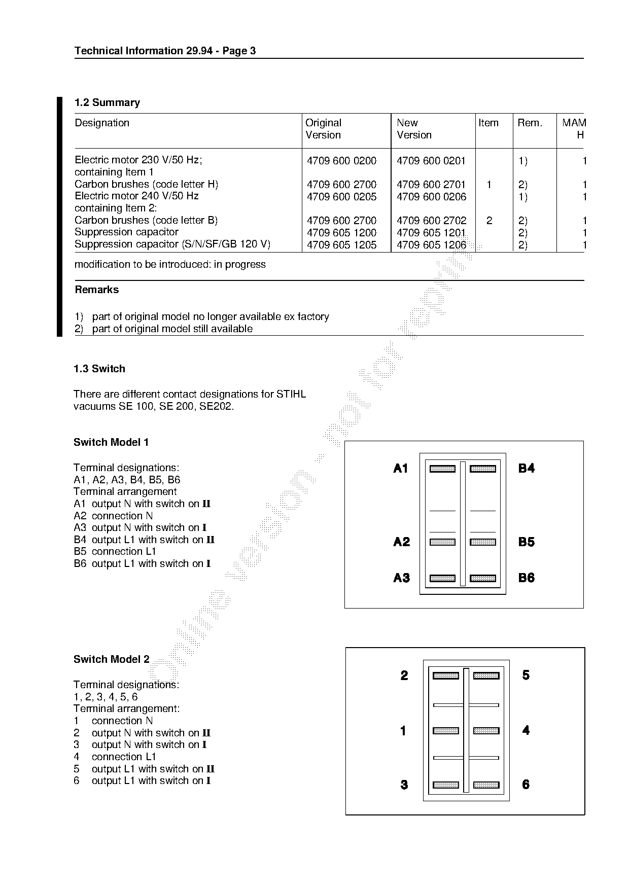
1.3 Switch
There are different contact designations for STIHL
vacuums SE 100, SE 200, SE202.

Switch Model 1

Terminal designations:
A1, A2, A3, B4, B5, B6

Terminal arrangement

A1 output N with switch on II
A2 connection N
A3 output N with switch on I
B4 output L1 with switch on II

B5 connection L1
B6 output L1 with switch on I

Switch Model 2

Terminal designations:
1, 2, 3, 4, 5, 6
Terminal arrangement:
1 connection N
2 output N with switch on II
3 output N with switch on I
4 connection L1
5 output L1 with switch on II
6 output L1 with switch on I
Page 4 of 7
Text of page 4 — search, copy, screen readers
Technical Information 29.94 - Page 4

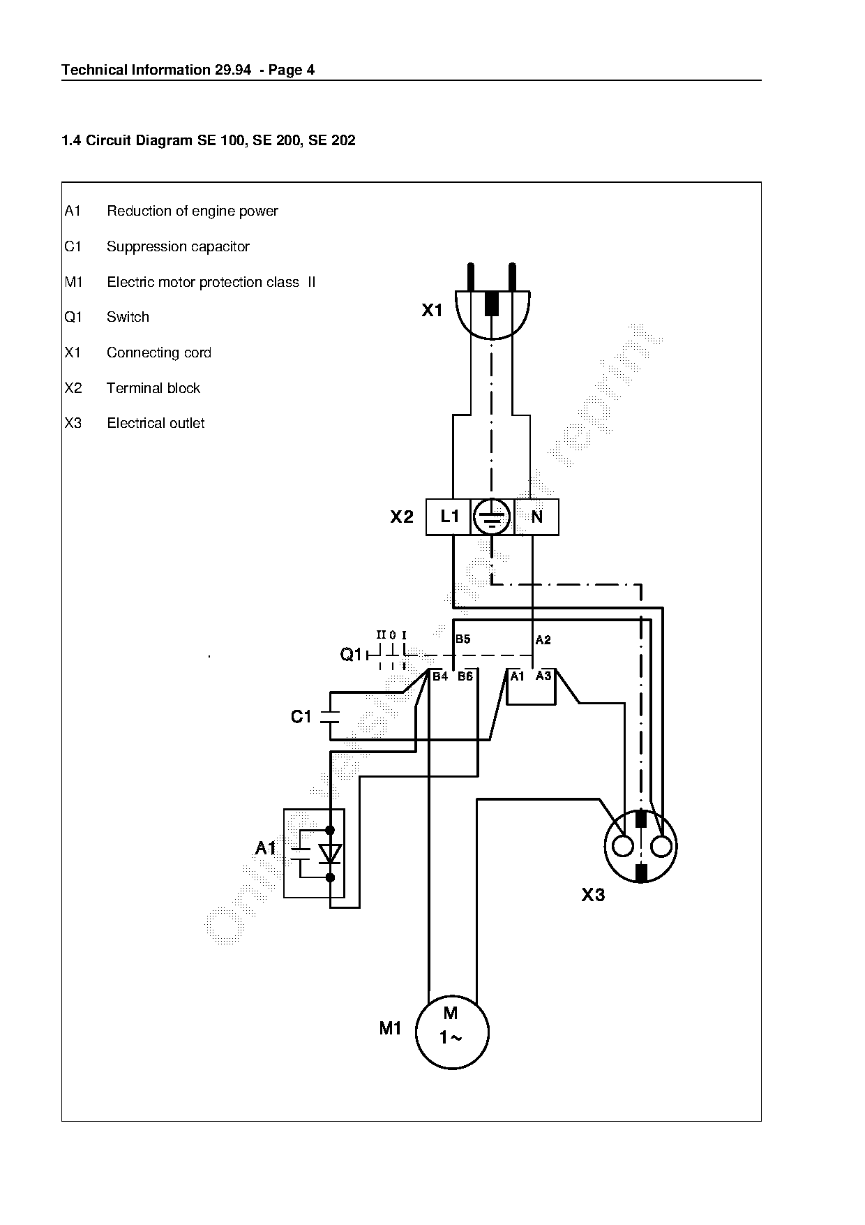
1.4 Circuit Diagram SE 100, SE 200, SE 202

A1    Reduction of engine power

C1    Suppression capacitor

M1    Electric motor protection class II

Q1    Switch

X1    Connecting cord

X2    Terminal block

X3    Electrical outlet
Page 5 of 7
Text of page 5 — search, copy, screen readers
Technical Information 29.94 - Page 5

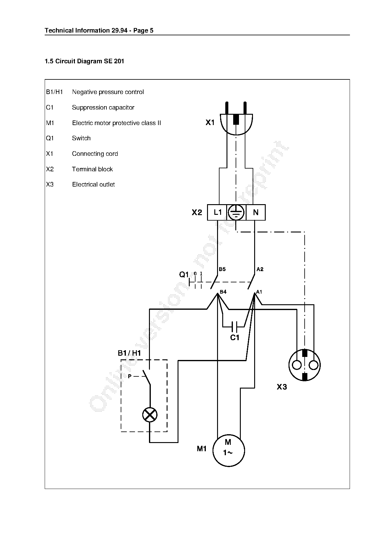
1.5 Circuit Diagram SE 201

B1/H1    Negative pressure control

C1       Suppression capacitor

M1       Electric motor protective class II

Q1       Switch

X1       Connecting cord

X2       Terminal block

X3       Electrical outlet
Page 6 of 7
Text of page 6 — search, copy, screen readers
Technical Information 29.94 - Page 6

2. SE 100, 200, 202:
   Retrofitting kit for automatic switch

2.1 Function

This retrofitting kit allows the vacuum to be
turned on by an extra device connected to the
built-in outlet; for example when vacuum is used
as suction device for a grinding machine.

Switch position I:
Vacuum runs at maximum rpm since power output

halving has to be removed during installation of

switching device.

Switch position II:

The built-in outlet is on. The vacuum only turns on
when a device is plugged into built-in outlet.
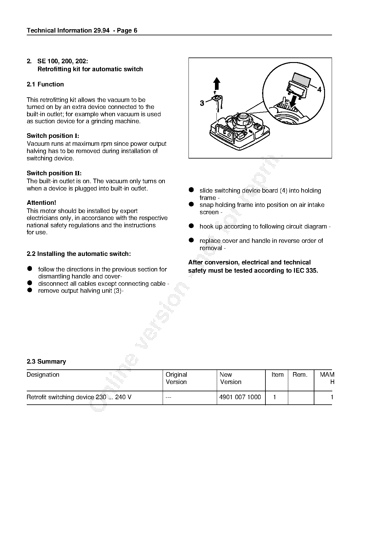
                                                                 • slide switching device board (4) into holding
                                                                   frame -
                                                                 • snap

Attention!                                                               holding frame into position on air intake
This motor should be installed by expert                           screen -
electricians only, in accordance with the respective
national safety regulations and the instructions
for use.
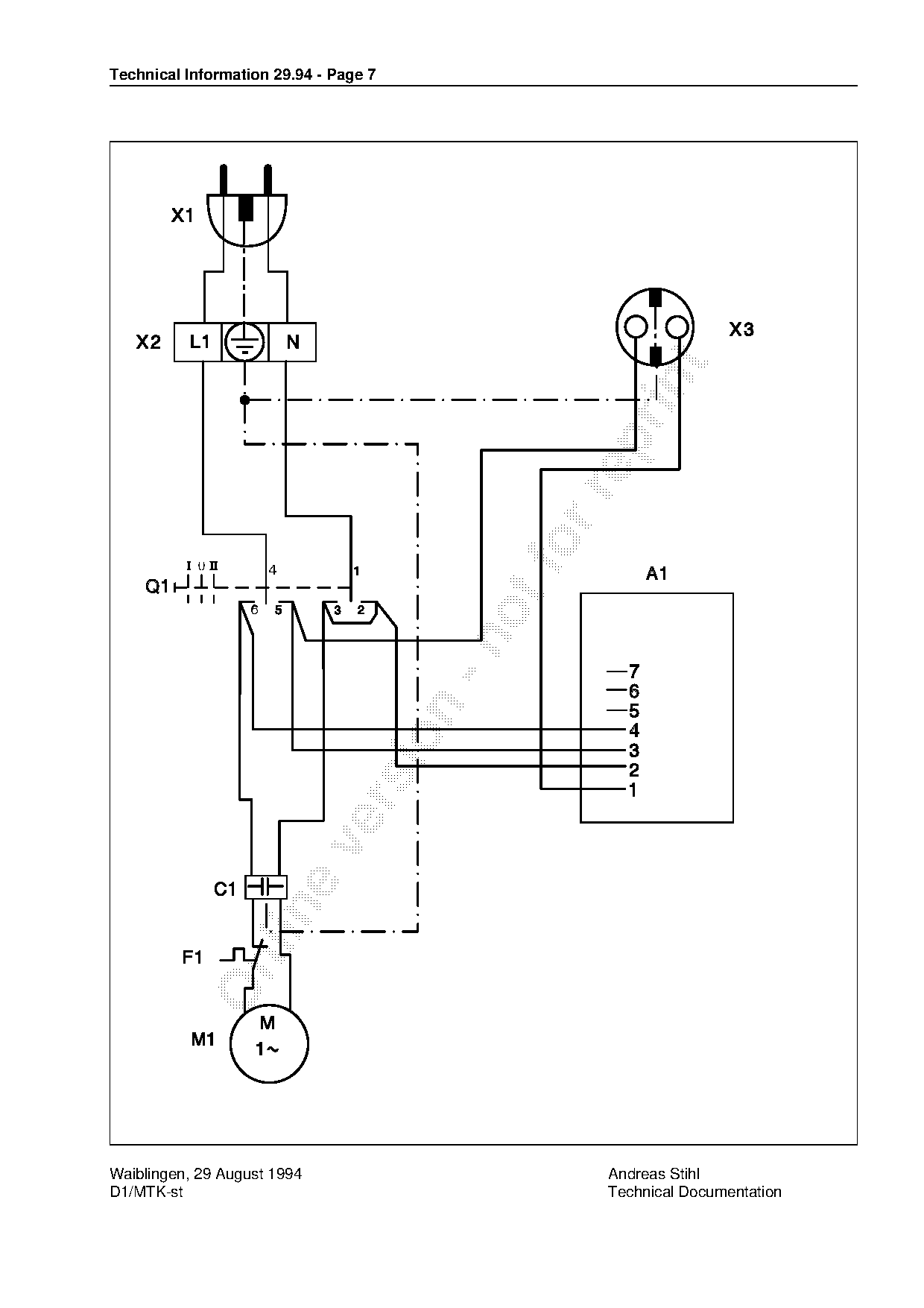
                                                                 • hook up according to following circuit diagram -
                                                                 • replace cover and handle in reverse order of
                                                                   removal -
2.2 Installing the automatic switch:

• follow
                                                                 After conversion, electrical and technical
         the directions in the previous section for              safety must be tested according to IEC 335.
  dismantling handle and cover-
• disconnect  all cables except connecting cable -
•

  remove   output  halving unit (3)-

2.3 Summary

Designation                                           Original              New               Item    Rem.      MAM
                                                      Version               Version                               H

Retrofit switching device 230 ... 240 V            ---                      4901 007 1000      1                     1
Page 7 of 7
Text of page 7 — search, copy, screen readers
Technical Information 29.94 - Page 7

Waiblingen, 29 August 1994                       Andreas Stihl
D1/MTK-st                                        Technical Documentation
Most of these PDFs embed fonts with a shifted character map, so the text above was recovered rather than copied — read it as a faithful but imperfect transcription, and treat the page image above each block as the authority where the two disagree — the figures exist only there, because they are vector drawings that text extraction cannot keep.