Technical Information · issue 34 of 1994
New augers; shaft extension; chuck; fuel pickup bo
IssueTI 34/1994
Part changes (1)
| Was | Becomes | What the bulletin says |
|---|---|---|
| 4117 350 3505 | 0000 350 3502 | In the interests of standardizing parts with other models, the original pickup body 4117 350 3505 will be replaced by the version 0000 350 3502. |
Full text
Page 1 of 4
Text of page 1 — search, copy, screen readers
Technical Information

                                                                                                        34.94

STIHL BT 106 Earth Auger - Series 4311

Contents

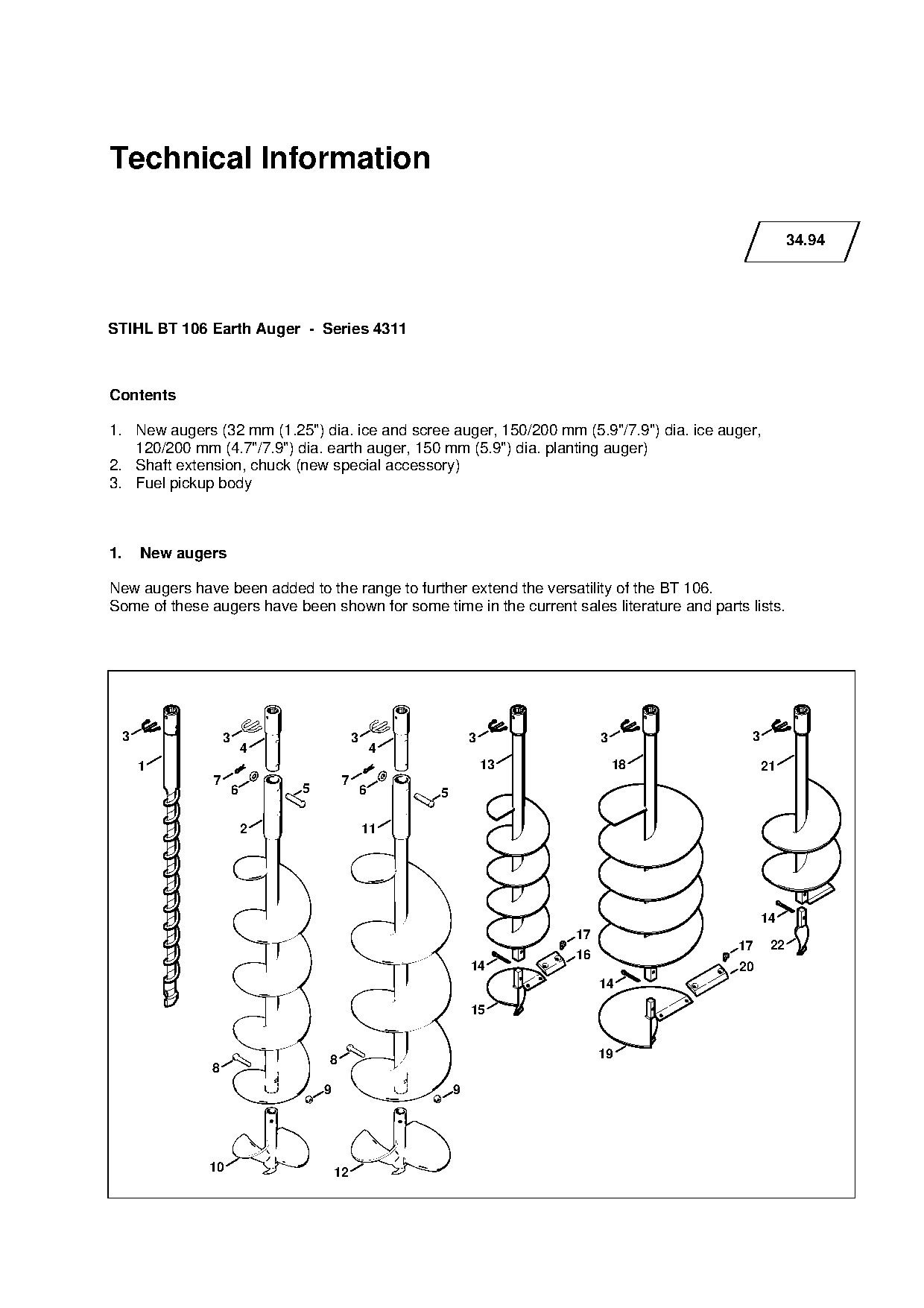
1. New augers (32 mm (1.25") dia. ice and scree auger, 150/200 mm (5.9"/7.9") dia. ice auger,

   120/200 mm (4.7"/7.9") dia. earth auger, 150 mm (5.9") dia. planting auger)
2. Shaft extension, chuck (new special accessory)
3. Fuel pickup body

1.   New augers                                                            fo
New augers have been added to the range to further extend the versatility of the BT 106.
Some of these augers have been shown for some time in the current sales literature and parts lists.

 3                 3                          3                   3              3            3
                           4                          4
     1                                                                13             18           21
               7                          7
                       6         5                6       5

                           2                      11

                                                                                                  14
                                                                            17
                                                                                             17    22
                                                                            16

                                                                  14                         20
                                                                                 14
                                                                  15

                                     8                                           19
               8
                                     9                        9

              10                         12
Page 2 of 4
Text of page 2 — search, copy, screen readers
Technical Information 34.94 - Page 2

Part Name                               Part No.         Key      Rem.   MOQ
                                                                         H

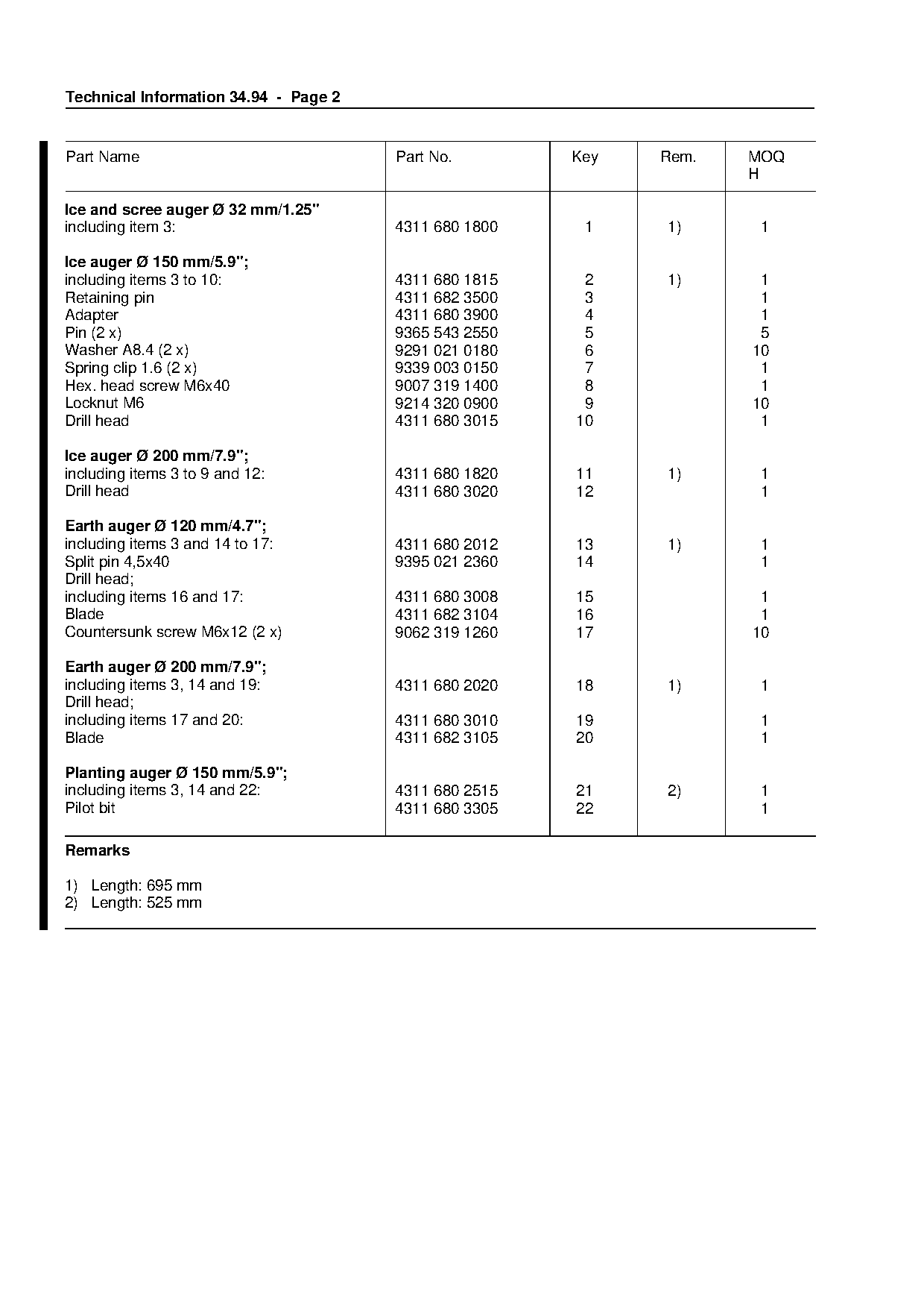
Ice and scree auger Ø 32 mm/1.25"
including item 3:                       4311 680 1800        1     1)     1

Ice auger Ø 150 mm/5.9";
including items 3 to 10:                4311 680 1815     2        1)     1
Retaining pin                           4311 682 3500     3               1
Adapter                                 4311 680 3900     4               1
Pin (2 x)                               9365 543 2550     5               5
Washer A8.4 (2 x)                       9291 021 0180     6              10

Spring clip 1.6 (2 x)                   9339 003 0150     7               1

Hex. head screw M6x40                   9007 319 1400     8               1
Locknut M6                              9214 320 0900     9              10
Drill head                              4311 680 3015    10               1

Ice auger Ø 200 mm/7.9";
including items 3 to 9 and 12:          4311 680 1820    11        1)     1
Drill head                              4311 680 3020    12               1

Earth auger Ø 120 mm/4.7";
including items 3 and 14 to 17:
Split pin 4,5x40
                                        4311 680 2012
                                        9395 021 2360
                                                         13
                                                         14
                                                                   1)     1
                                                                          1
Drill head;
including items 16 and 17:
                                        4311 680 3008    15               1
Blade                                   4311 682 3104    16               1
Countersunk screw M6x12 (2 x)           9062 319 1260    17              10

Earth auger Ø 200 mm/7.9";
including items 3, 14 and 19:           4311 680 2020    18        1)     1
Drill head;

including items 17 and 20:              4311 680 3010    19               1

Blade                                   4311 682 3105    20               1

Planting auger Ø 150 mm/5.9";
including items 3, 14 and 22:           4311 680 2515    21        2)     1

Pilot bit                               4311 680 3305    22               1

Remarks

1) Length: 695 mm
2) Length: 525 mm
Page 3 of 4
Text of page 3 — search, copy, screen readers
Technical Information 34.94 - Page 3

2. Shaft extension, chuck

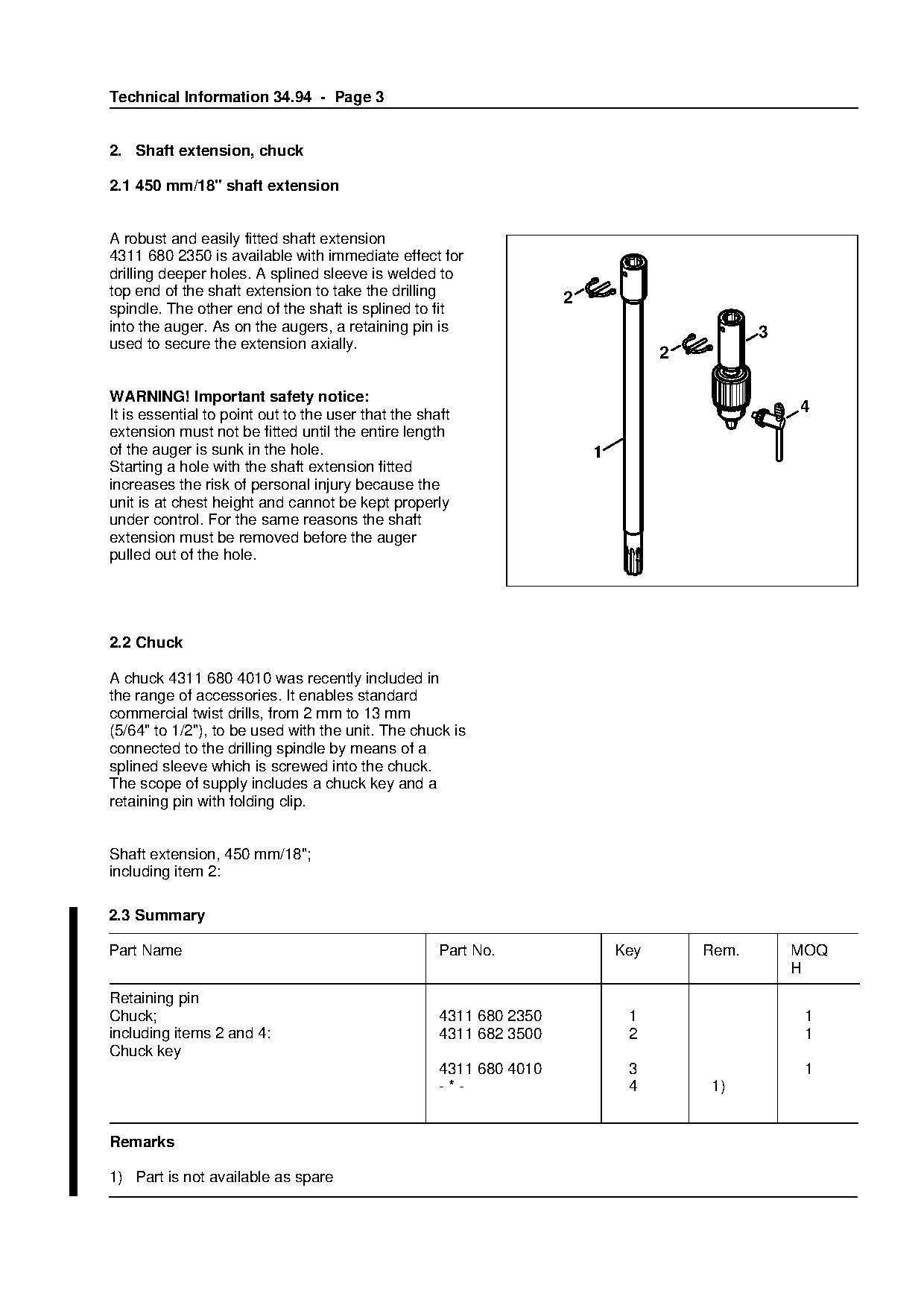
2.1 450 mm/18" shaft extension

A robust and easily fitted shaft extension
4311 680 2350 is available with immediate effect for
drilling deeper holes. A splined sleeve is welded to
top end of the shaft extension to take the drilling                  2
spindle. The other end of the shaft is splined to fit
into the auger. As on the augers, a retaining pin is                                          3
used to secure the extension axially.
                                                                                   2

WARNING! Important safety notice:
It is essential to point out to the user that the shaft                                           4
extension must not be fitted until the entire length

of the auger is sunk in the hole.                                        1
Starting a hole with the shaft extension fitted
increases the risk of personal injury because the

unit is at chest height and cannot be kept properly
under control. For the same reasons the shaft
extension must be removed before the auger
pulled out of the hole.                                         fo

2.2 Chuck

A chuck 4311 680 4010 was recently included in
the range of accessories. It enables standard

commercial twist drills, from 2 mm to 13 mm
(5/64" to 1/2"), to be used with the unit. The chuck is

connected to the drilling spindle by means of a
splined sleeve which is screwed into the chuck.
The scope of supply includes a chuck key and a
retaining pin with folding clip.

Shaft extension, 450 mm/18";
including item 2:

2.3 Summary

Part Name                                            Part No.                Key       Rem.       MOQ

                                                                                                  H
Retaining pin
Chuck;                                               4311 680 2350            1                    1
including items 2 and 4:                             4311 682 3500            2                    1
Chuck key
                                                     4311 680 4010            3                    1
                                                     -*-                      4        1)

Remarks

1) Part is not available as spare
Page 4 of 4
Text of page 4 — search, copy, screen readers
Technical Information 34.94 - Page 4

3. Fuel pickup body

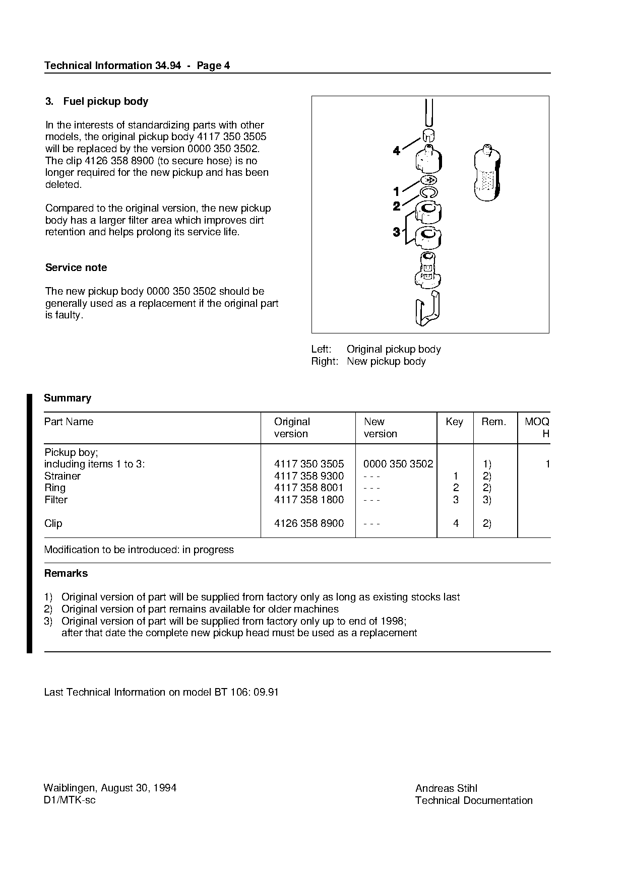
In the interests of standardizing parts with other
models, the original pickup body 4117 350 3505
will be replaced by the version 0000 350 3502.
The clip 4126 358 8900 (to secure hose) is no
longer required for the new pickup and has been
deleted.

Compared to the original version, the new pickup
body has a larger filter area which improves dirt
retention and helps prolong its service life.

Service note

The new pickup body 0000 350 3502 should be

generally used as a replacement if the original part
is faulty.

                                                                Left: Original pickup body
                                                                Right: New pickup body
Summary

Part Name                                            Original             New                Key   Rem.   MOQ

                                                     version              version                           H
Pickup boy;
including items 1 to 3:                              4117 350 3505        0000 350 3502            1)         1
Strainer                                             4117 358 9300        ---                 1    2)

Ring                                                 4117 358 8001        ---                 2    2)

Filter                                               4117 358 1800        ---                 3    3)

Clip                                                 4126 358 8900        ---                 4    2)

Modification to be introduced: in progress

Remarks

1) Original version of part will be supplied from factory only as long as existing stocks last
2) Original version of part remains available for older machines

3) Original version of part will be supplied from factory only up to end of 1998;
   after that date the complete new pickup head must be used as a replacement

Last Technical Information on model BT 106: 09.91

Waiblingen, August 30, 1994                                                         Andreas Stihl
D1/MTK-sc                                                                           Technical Documentation
Most of these PDFs embed fonts with a shifted character map, so the text above was recovered rather than copied — read it as a faithful but imperfect transcription, and treat the page image above each block as the authority where the two disagree — the figures exist only there, because they are vector drawings that text extraction cannot keep.