Technical Information · issue 2 of 1995
Uprated engine
Model HS 72, 74 and 76 hedge trimmers from
IssueTI 2/1995
From serial 30 314 341
Full text
Page 1 of 3
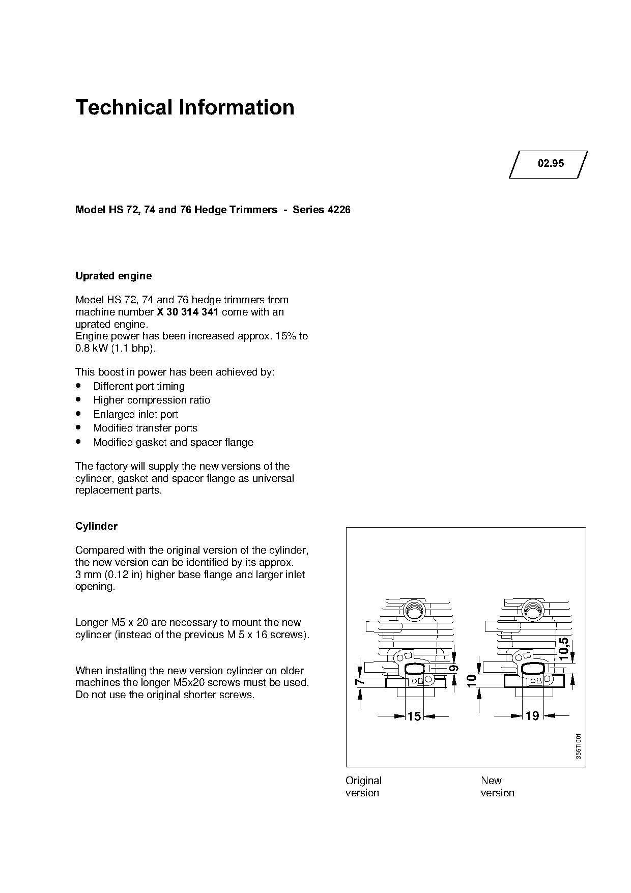
Text of page 1 — search, copy, screen readers
Technical Information

                                                                                           02.95

Model HS 72, 74 and 76 Hedge Trimmers  -  Series 4226

Uprated engine

Model HS 72, 74 and 76 hedge trimmers from
machine number X 30 314 341=come with an
uprated engine.
Engine power has been increased approx. 15% to

0.8 kW (1.1 bhp).

This boost in power has been achieved by:
•   Different port timing
•   Higher compression ratio
•   Enlarged inlet port
•   Modified transfer ports

•   Modified gasket and spacer flange

The factory will supply the new versions of the
cylinder, gasket and spacer flange as universal

replacement parts.

&\OLQGHU

Compared with the original version of the cylinder,
the new version can be identified by its approx.
3 mm (0.12 in) higher base flange and larger inlet

opening.

Longer M5 x 20 are necessary to mount the new
cylinder (instead of the previous M 5 x 16 screws).
                                                                                               10,5


When installing the new version cylinder on older
                                                                           10

machines the longer M5x20 screws must be used.
                                                        7

Do not use the original shorter screws.

                                                                 15                       19
                                                                                                      356TI001

                                                      Original                  New
                                                      version                   version
Page 2 of 3
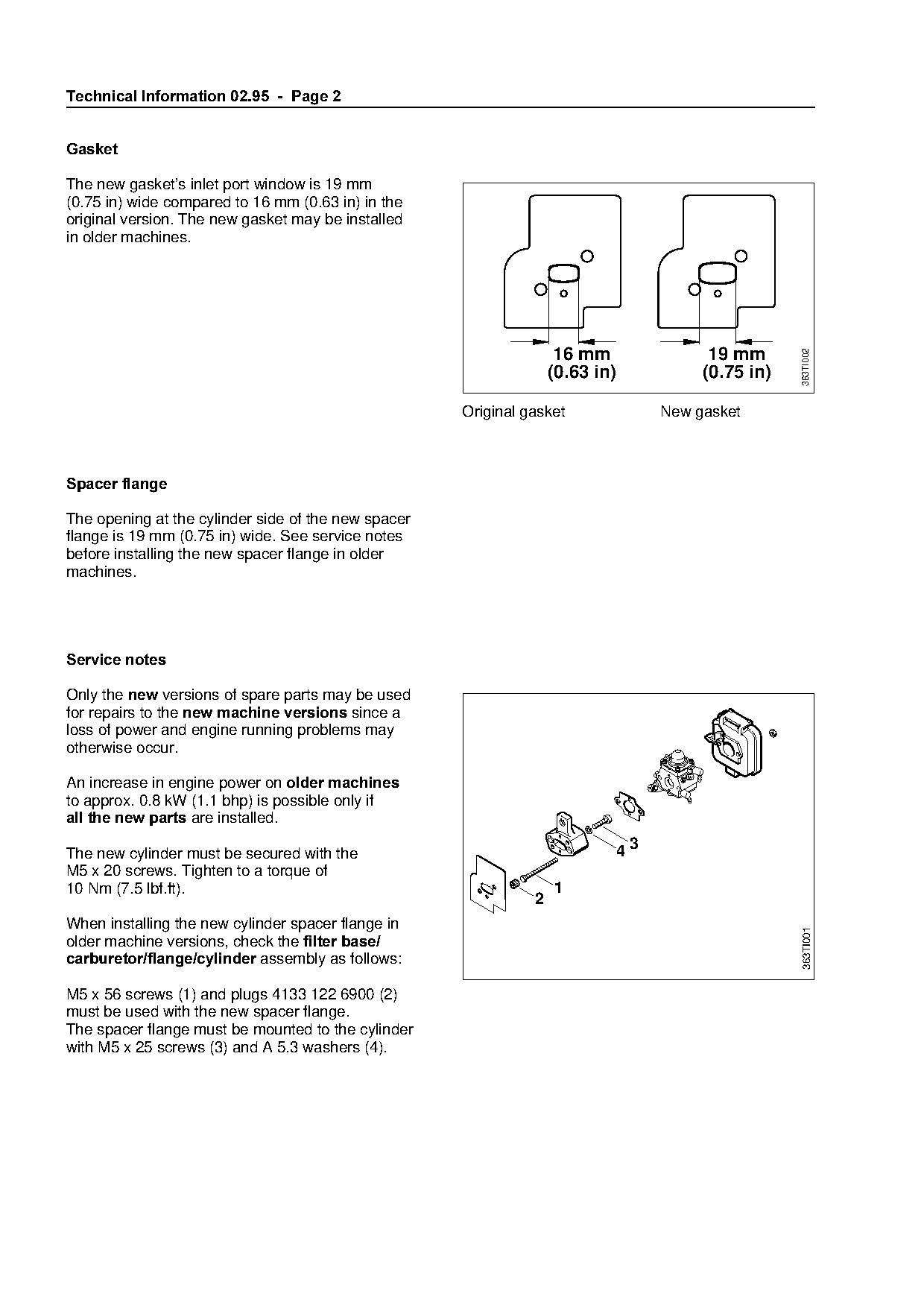
Text of page 2 — search, copy, screen readers
Technical Information 02.95  -  Page 2

*DVNHW

The new gasket’s inlet port window is 19 mm
(0.75 in) wide compared to 16 mm (0.63 in) in the
original version. The new gasket may be installed
in older machines.

                                                                       16 mm                 19 mm

                                                                                                        363TI002
                                                                      (0.63 in)             (0.75 in)

                                                        Original gasket                New gasket

Spacer flange

The opening at the cylinder side of the new spacer
flange is 19 mm (0.75 in) wide. See service notes
before installing the new spacer flange in older
machines.

Service notes

Only the QHZ versions of spare parts may be used

for=rep~irs=to=the=new machine versions=since=~
loss of power and engine running problems may

otherwise occur.

An increase in engine power on older machines
to approx. 0.8 kW (1.1 bhp) is possible only if

all the new parts=~re=inst~lledK


The new cylinder must be secured with the
M5 x 20 screws. Tighten to a torque of
10 Nm (7.5 lbf.ft).                                                   1
                                                                  2

When installing the new cylinder spacer flange in
                                                                                                        363TI001

older machine versions, check the filter base/
carburetor/flange/cylinder=~ssembly as follows:

M5 x 56 screws (1) and plugs 4133 122 6900 (2)
must be used with the new spacer flange.
The spacer flange must be mounted to the cylinder
with M5 x 25 screws (3) and A 5.3 washers (4).
Page 3 of 3
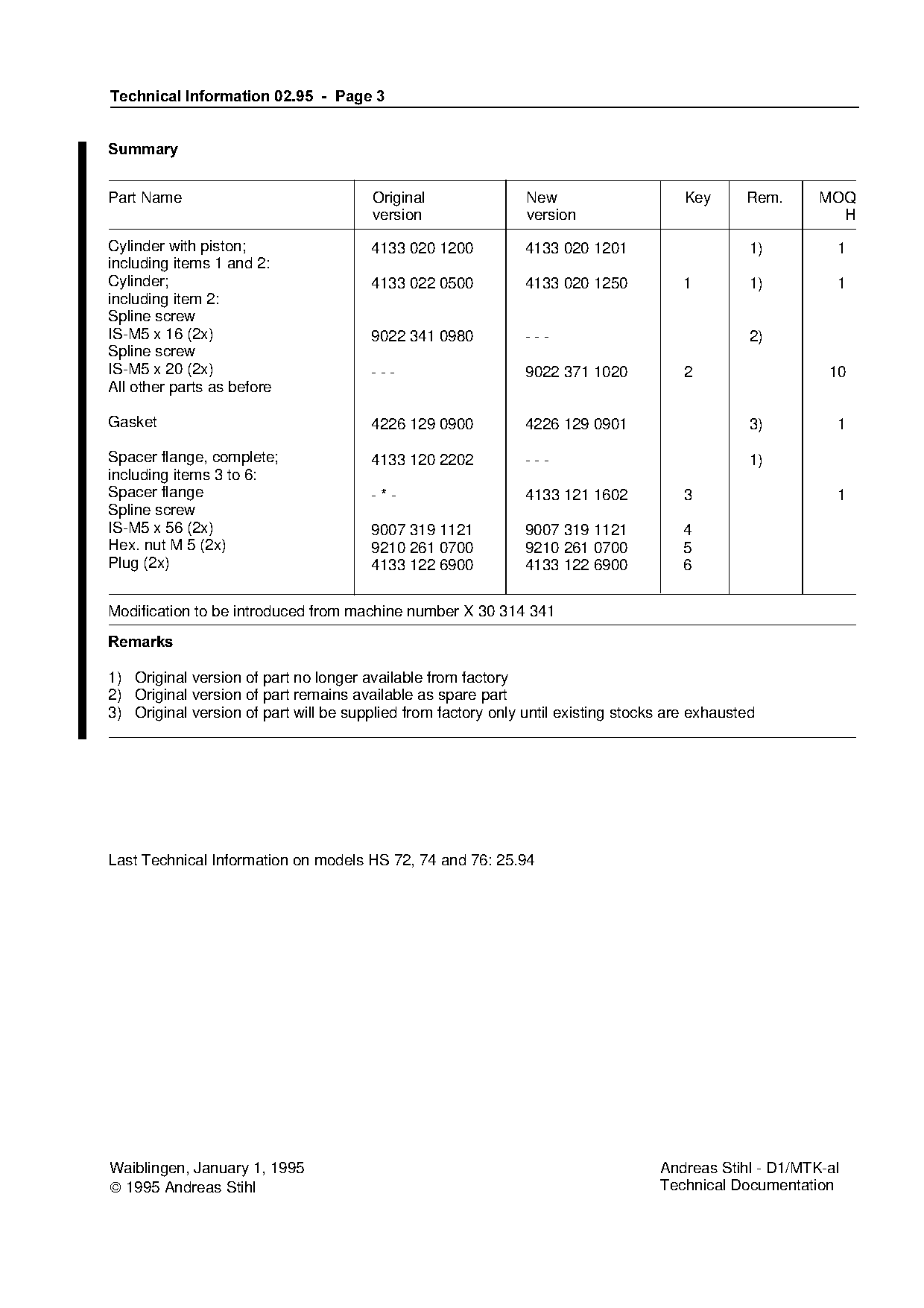
Text of page 3 — search, copy, screen readers
Technical Information 02.95 - Page 3
6XPPDU\
Part Name Original New Key Rem. MOQ
version version H
Cylinder with piston; 4133 020 1200 4133 020 1201 1) 1
including items 1 and 2:
Cylinder; 4133 022 0500 4133 020 1250 1 1) 1
including item 2:
Spline screw
IS-M5 x 16 (2x) 9022 341 0980 --- 2)
Spline screw
IS-M5 x 20 (2x) --- 9022 371 1020 2 10
All other parts as before
Gasket 4226 129 0900 4226 129 0901 3) 1
Spacer flange, complete; 4133 120 2202 --- 1)
including items 3 to 6:
Spacer flange
-*- 4133 121 1602 3 1
Spline screw
IS-M5 x 56 (2x) 9007 319 1121 9007 319 1121 4
Hex. nut M 5 (2x)
Plug (2x)
9210 261 0700
4133 122 6900
fo9210 261 0700
4133 122 6900
5
6
Modification to be introduced from machine number X 30 314 341
5HPDUNV
1) Original version of part no longer available from factory
2) Original version of part remains available as spare part
3) Original version of part will be supplied from factory only until existing stocks are exhausted
Last Technical Information on models HS 72, 74 and 76: 25.94
Waiblingen, January 1, 1995 Andreas Stihl - D1/MTK-al
1995 Andreas Stihl Technical Documentation Most of these PDFs embed fonts with a shifted character map, so the text above was recovered rather than copied — read it as a faithful but imperfect transcription, and treat the page image above each block as the authority where the two disagree — the figures exist only there, because they are vector drawings that text extraction cannot keep.