Technical Information · issue 4 of 1995
New FR 108 Backpack Brushcutter
IssueTI 4/1995
Full text
Page 1 of 11
Text of page 1 — search, copy, screen readers
Technical Information

                                                                                                 04.95

New STIHL FR 108 Backpack Brushcutter  -  Series 4135

1.====General description

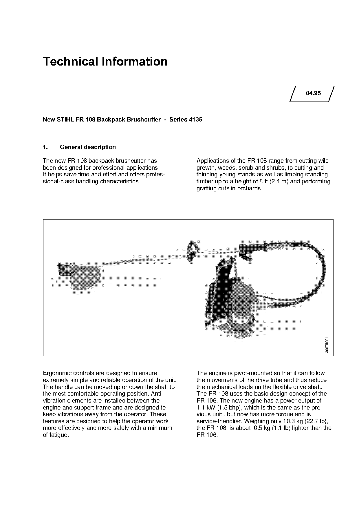
The new FR 108 backpack brushcutter has                Applications of the FR 108 range from cutting wild
been designed for professional applications.           growth, weeds, scrub and shrubs, to cutting and

It helps save time and effort and offers profes-       thinning young stands as well as limbing standing
sional-class handling characteristics.                 timber up to a height of 8 ft (2.4 m) and performing
                                                       grafting cuts in orchards.

                                                                                                         360TII001

Ergonomic controls are designed to ensure              The engine is pivot-mounted so that it can follow

extremely simple and reliable operation of the unit.   the movements of the drive tube and thus reduce
The handle can be moved up or down the shaft to        the mechanical loads on the flexible drive shaft.
the most comfortable operating position. Anti-         The FR 108 uses the basic design concept of the
vibration elements are installed between the           FR 106. The new engine has a power output of
engine and support frame and are designed to           1.1 kW (1.5 bhp), which is the same as the pre-
keep vibrations away from the operator. These          vious unit , but now has more torque and is
features are designed to help the operator work        service-friendlier. Weighing only 10.3 kg (22.7 lb),
more effectively and more safely with a minimum        the FR 108 is about 0.5 kg (1.1 lb) lighter than the
of fatigue.                                            FR 106.
Page 2 of 11
Text of page 2 — search, copy, screen readers
Technical Information 04.95  -  Page 2

2.=======Cutting tools
                                                                1===================2
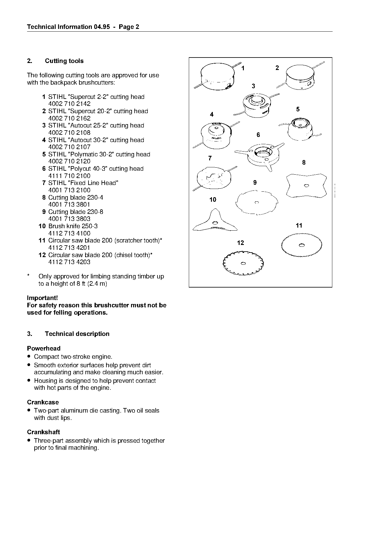
The following cutting tools are approved for use

                                                                                                                      681FK003
                                                                 681FK001
with the backpack brushcutters:
                                                                            3
       1=pqfei=?pupercut 2-2" cutting head
         4002 710 2142

                                                                                        681FK006
       2=pqfei=?pupercut 20-2" cutting head                                                                   5
                                                          4
         4002 710 2162
       3=pqfei=?^utocut 25-2" cutting head
         QMMO=TNM=ONMU==========================================================6

                                                                681FK007
       4=pqfei=?^utocut 30-2" cutting head
         4002 710 2107

       5=pqfei=?molymatic 30-2" cutting head

                                                          7
         QMMO=TNM=ONOM============================================================================================8

                                                                                                   681FK012
       6=pqfei=?molycut 40-3" cutting head
         4111 710 2100

       7=pqfei=?cixed Line Head"

                                                                                                                                 681FK013
         4001 713 2100
       8=`utting blade OPMJQ==============================10

         4001 713 3801
       9=`utting blade 230-8
         4001 713 3803
      10=_rush knife 250-3
         4112 713 4100
                                                          fo                                                  11

      11=`ircular saw blade 200 (scratcher toothF==============12
         4112 713 4201
      12=`ircular saw blade 200 (chisel tooth)

         4112 713 4203

*     Only approved for limbing standing timber up
      to a height of 8 ft (2.4 m)

Important!

For safety reason this brushcutter must not be
used for felling operations.

3.=======Technical description

3RZHUKHDG
• Compact two-stroke engine.
• Smooth exterior surfaces help prevent dirt

  accumulating and make cleaning much easier.
• Housing is designed to help prevent contact
  with hot parts of the engine.

&UDQNFDVH
• Two-part aluminum die casting. Two oil seals
     with dust lips.

&UDQNVKDIW
• Three-part assembly which is pressed together
     prior to final machining.
Page 3 of 11
Text of page 3 — search, copy, screen readers
Technical Information 04.95  -  Page 3

3LVWRQ
• Aluminum alloy piston with two compression
  rings.
• Piston pin is supported in a needle cage and
  located by hookless wire snap rings.

&\OLQGHU
• Special aluminum alloy.
• Bore electroplated with a extremely wear
  resistant special alloy.

&DUEXUHWRU

• Diaphragm carburetor, secured to cylinder with

  thermally insulated mounting.

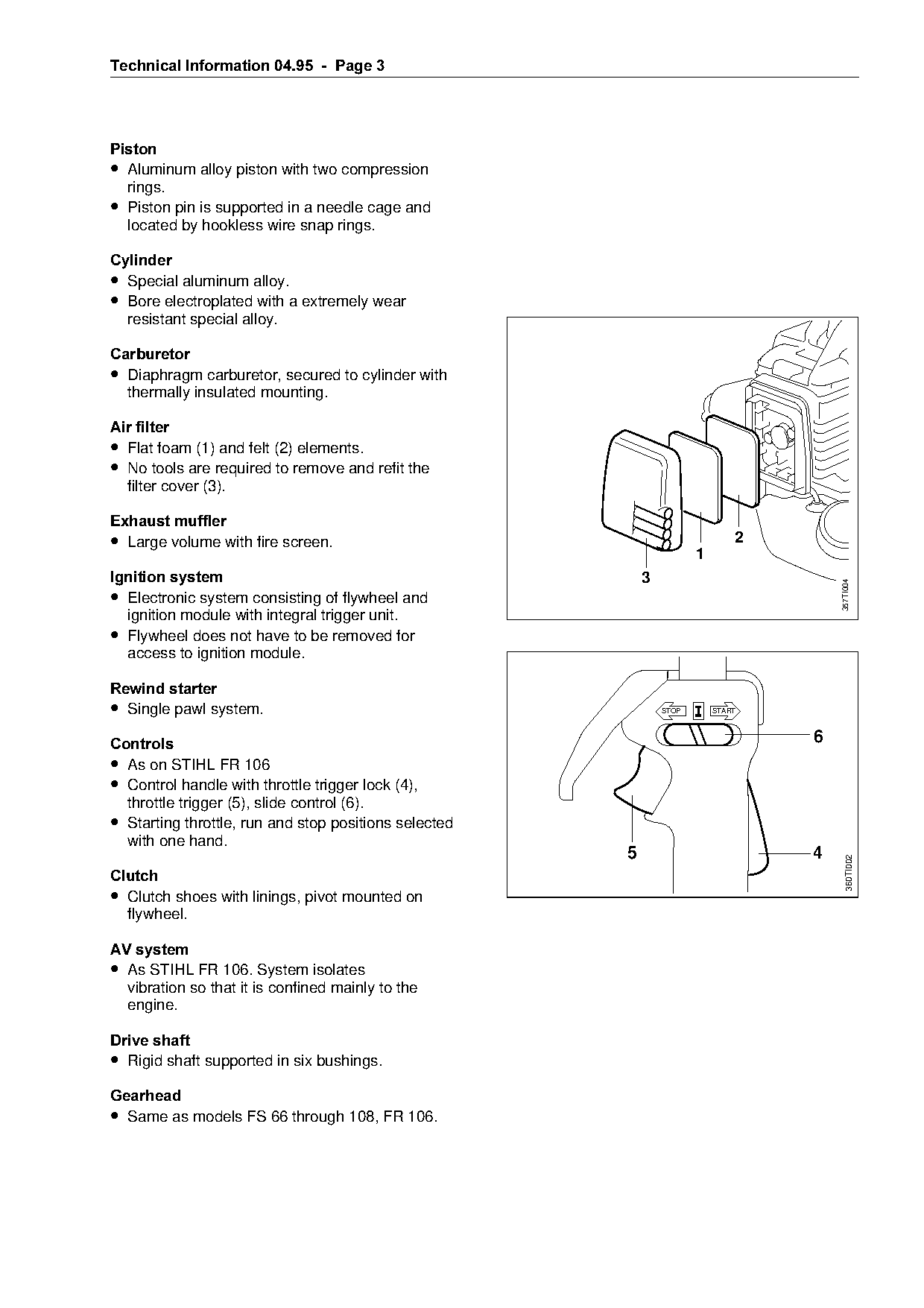
Air filter

• Flat foam (1) and felt (2) elements.
• No tools are required to remove and refit the
  filter cover (3).

Exhaust muffler
• Large volume with fire screen.                        fo                           2
                                                                             1
Ignition system===================================================P

                                                                                             357TI004
• Electronic system consisting of flywheel and
  ignition module with integral trigger unit.
• Flywheel does not have to be removed for

  access to ignition module.

Rewind starter
• Single pawl system.

                                                                      STOP       START


&RQWUROV
• As on STIHL FR 106
• Control handle with throttle trigger lock (4),

  throttle trigger (5), slide control (6).
• Starting throttle, run and stop positions selected
  with one hand.

                                                              5                          4      360TI002

&OXWFK
• Clutch shoes with linings, pivot mounted on

  flywheel.

AV system

• As STIHL FR 106. System isolates
  vibration so that it is confined mainly to the
  engine.

Drive shaft
• Rigid shaft supported in six bushings.
*HDUKHDG
• Same as models FS 66 through 108, FR 106.
Page 4 of 11
Text of page 4 — search, copy, screen readers
Technical Information 04.95  -  Page 4

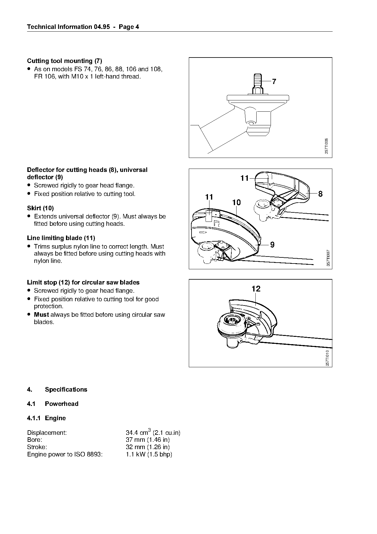
Cutting tool mounting =7
• As on models FS 74, 76, 86, 88, 106 and 108,
  FR 106, with M10 x 1 left-hand thread.
                                                                            7

                                                                                    357TI006
Deflector for cutting heads =8=, universal
deflector =9======================================================NN

• Screwed rigidly to gear head flange.
• Fixed position relative to cutting tool.                  11                  8

                                                                 10
Skirt =10
• Extends universal deflector (9). Must always be
  fitted before using cutting heads.                         fo
Line limiting blade =11
• Trims surplus nylon line to correct length. Must
                                                                            9

                                                                                       357TI007
  always be fitted before using cutting heads with
  nylon line.

Limit stop =12= for circular saw blades
• Screwed rigidly to gear head flange.                                 12

• Fixed position relative to cutting tool for good

     protection.
• 0XVW always be fitted before using circular saw
     blades.

                                                                                     357TI010

4.=======Specifications

4.1======Powerhead

4.1.1=Engine

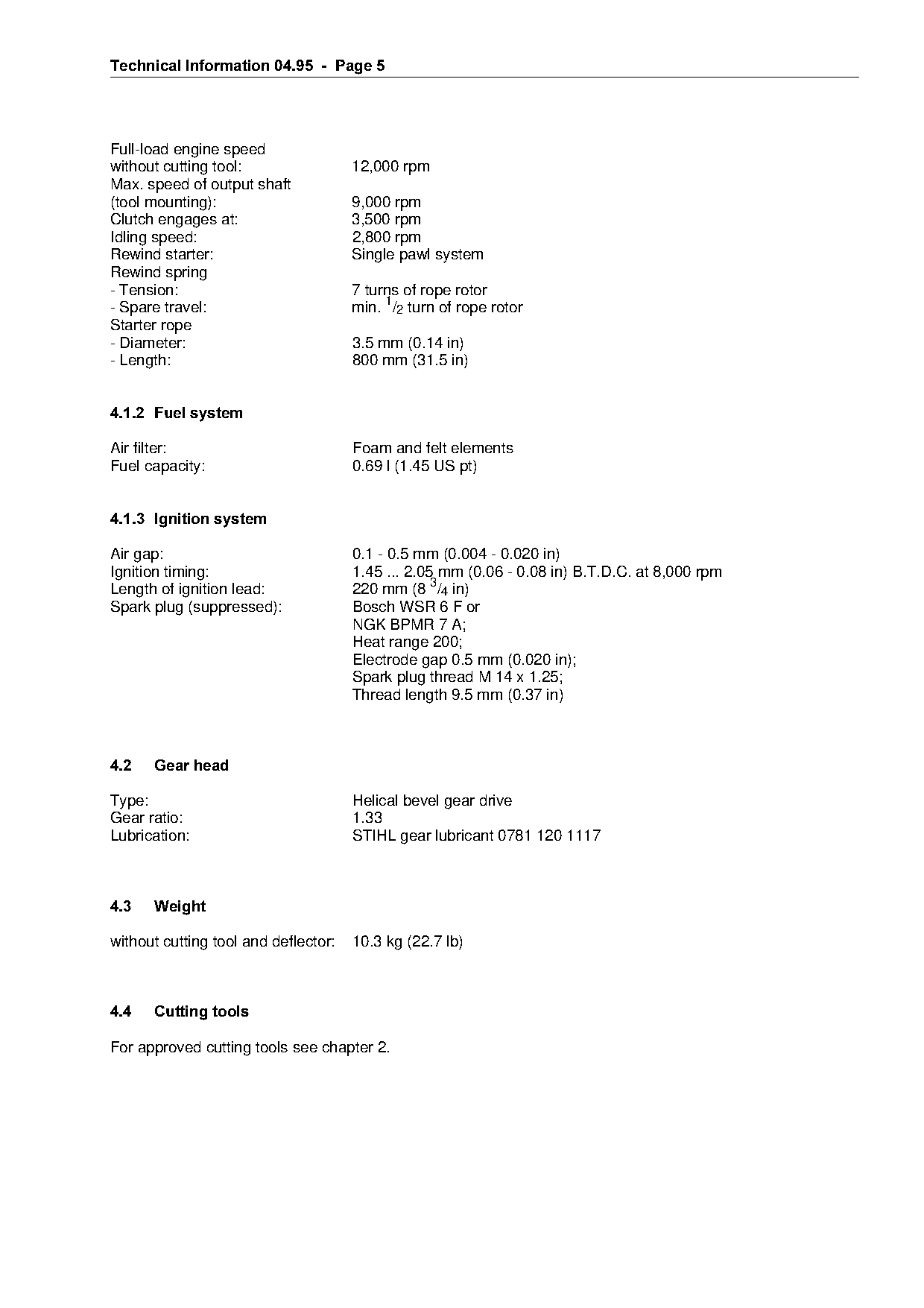
Displacement:                        34.4 cm3 (2.1 cu.in)
Bore:                                37 mm (1.46 in)
Stroke:                              32 mm (1.26 in)
Engine power to ISO 8893:            1.1 kW (1.5 bhp)
Page 5 of 11
Text of page 5 — search, copy, screen readers
Technical Information 04.95  -  Page 5

Full-load engine speed
without cutting tool:                 12,000 rpm
Max. speed of output shaft
(tool mounting):                      9,000 rpm
Clutch engages at:                    3,500 rpm
Idling speed:                         2,800 rpm
Rewind starter:                       Single pawl system
Rewind spring
- Tension:                            7 turns of rope rotor
- Spare travel:                       min. 1/2 turn of rope rotor
Starter rope
- Diameter:                           3.5 mm (0.14 in)
- Length:                             800 mm (31.5 in)

4.1.2=Fuel system

Air filter:                           Foam and felt elements
Fuel capacity:                        0.69 l (1.45 US pt)

4.1.3=Ignition system

Air gap:
Ignition timing:
                                      0.1 - 0.5 mm (0.004 - 0.020 in)
                                      1.45 ... 2.05 mm (0.06 - 0.08 in) B.T.D.C. at 8,000 rpm
Length of ignition lead:              220 mm (8 3/4 in)
Spark plug (suppressed):              Bosch WSR 6 F or
                                      NGK BPMR 7 A;

                                      Heat range 200;
                                      Electrode gap 0.5 mm (0.020 in);
                                      Spark plug thread M 14 x 1.25;
                                      Thread length 9.5 mm (0.37 in)

4.2===Gear head

Type:                                 Helical bevel gear drive

Gear ratio:                           1.33
Lubrication:                          STIHL gear lubricant 0781 120 1117

4.3===Weight

without cutting tool and deflector:   10.3 kg (22.7 lb)

4.4===Cutting tools

For approved cutting tools see chapter 2.
Page 6 of 11
Text of page 6 — search, copy, screen readers
Technical Information 04.95  -  Page 6

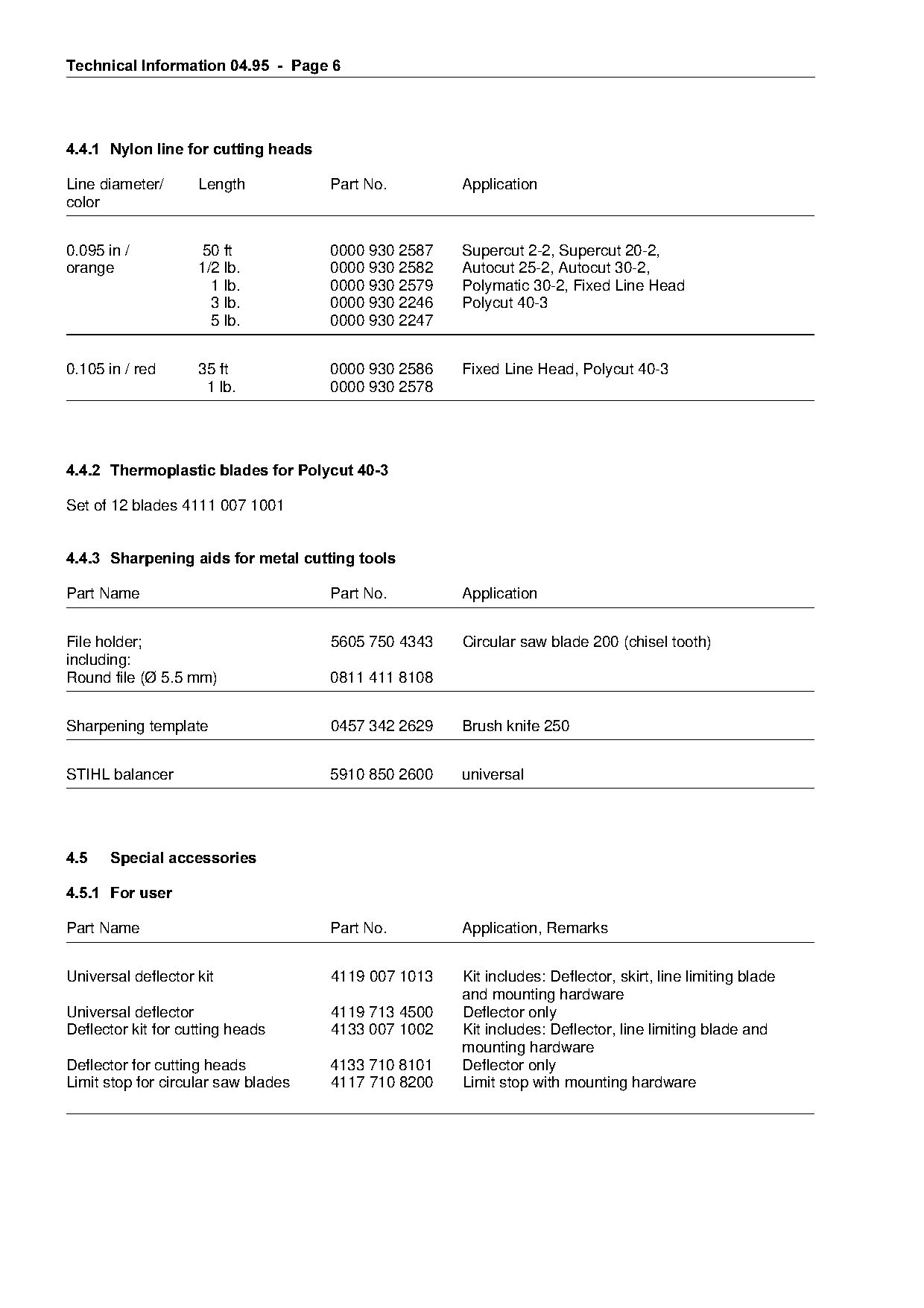
4.4.1=Nylon line for cutting heads

Line diameter/      Length           Part No.        Application
color

0.095 in /           50 ft           0000 930 2587   Supercut 2-2, Supercut 20-2,
orange              1/2 lb.          0000 930 2582   Autocut 25-2, Autocut 30-2,
                      1 lb.          0000 930 2579   Polymatic 30-2, Fixed Line Head
                      3 lb.          0000 930 2246   Polycut 40-3
                      5 lb.          0000 930 2247

0.105 in / red      35 ft            0000 930 2586   Fixed Line Head, Polycut 40-3

                     1 lb.           0000 930 2578

4.4.2=Thermoplastic blades for Polycut 40-3

Set of 12 blades 4111 007 1001

4.4.3=Sharpening aids for metal cutting tools
Part Name                            Part No.        Application

File holder;                         5605 750 4343   Circular saw blade 200 (chisel tooth)
including:
Round file (Ø 5.5 mm)                0811 411 8108

Sharpening template                  0457 342 2629   Brush knife 250

STIHL balancer                       5910 850 2600   universal

4.5===Special accessories

4.5.1=For user

Part Name                            Part No.        Application, Remarks

Universal deflector kit              4119 007 1013   Kit includes: Deflector, skirt, line limiting blade
                                                     and mounting hardware
Universal deflector                  4119 713 4500   Deflector only
Deflector kit for cutting heads      4133 007 1002   Kit includes: Deflector, line limiting blade and
                                                     mounting hardware
Deflector for cutting heads          4133 710 8101   Deflector only
Limit stop for circular saw blades   4117 710 8200   Limit stop with mounting hardware
Page 7 of 11
Text of page 7 — search, copy, screen readers
Technical Information 04.95  -  Page 7

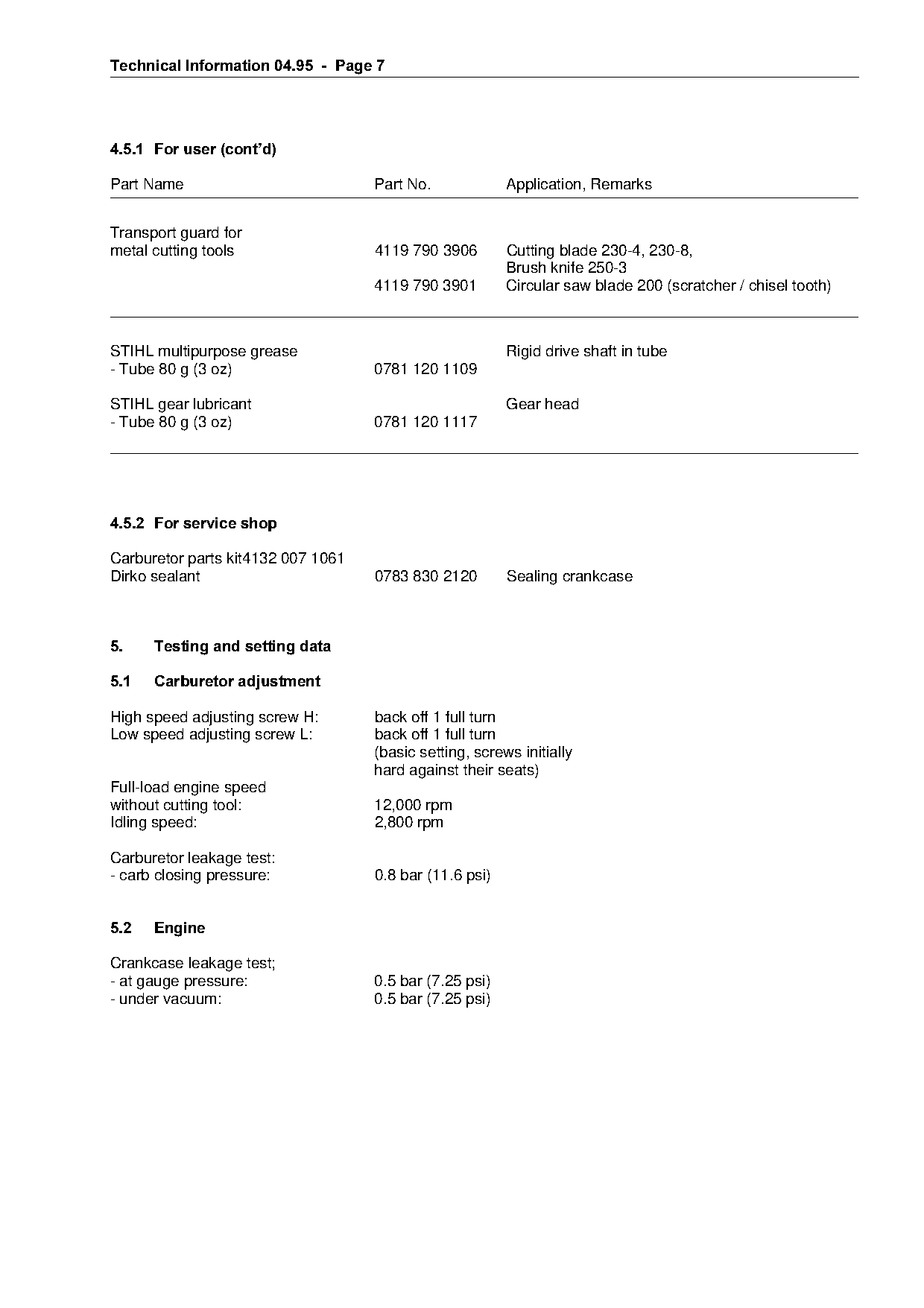
4.5.1=For user =cont¶d

Part Name                           Part No.             Application, Remarks

Transport guard for
metal cutting tools                 4119 790 3906        Cutting blade 230-4, 230-8,
                                                         Brush knife 250-3
                                    4119 790 3901        Circular saw blade 200 (scratcher / chisel tooth)

STIHL multipurpose grease                                Rigid drive shaft in tube

- Tube 80 g (3 oz)                  0781 120 1109

STIHL gear lubricant                                     Gear head
- Tube 80 g (3 oz)                  0781 120 1117

4.5.2=For service shop

Carburetor parts kit4132 007 1061
Dirko sealant                       0783 830 2120
                                                         Sealing crankcase

5.====Testing and setting data

5.1===Carburetor adjustment

High speed adjusting screw H:       back off 1 full turn
Low speed adjusting screw L:        back off 1 full turn

                                    (basic setting, screws initially
                                    hard against their seats)
Full-load engine speed

without cutting tool:               12,000 rpm
Idling speed:                       2,800 rpm

Carburetor leakage test:
- carb closing pressure:            0.8 bar (11.6 psi)

5.2===Engine

Crankcase leakage test;
- at gauge pressure:                0.5 bar (7.25 psi)
- under vacuum:                     0.5 bar (7.25 psi)
Page 8 of 11
Text of page 8 — search, copy, screen readers
Technical Information 04.95  -  Page 8

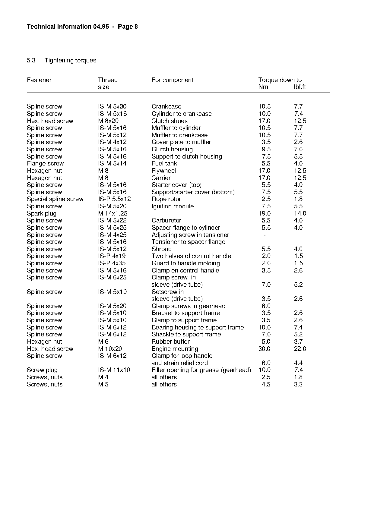
5.3   Tightening torques

Fastener                   Thread         For component                          Torque down to
                           size                                                  Nm         lbf.ft

Spline screw               IS-M 5x30      Crankcase                              10.5        7.7
Spline screw               IS-M 5x16      Cylinder to crankcase                  10.0        7.4
Hex. head screw            M 8x20         Clutch shoes                           17.0        12.5
Spline screw               IS-M 5x16      Muffler to cylinder                    10.5        7.7
Spline screw               IS-M 5x12      Muffler to crankcase                   10.5        7.7
Spline screw               IS-M 4x12      Cover plate to muffler                  3.5        2.6

Spline screw               IS-M 5x16      Clutch housing                          9.5        7.0

Spline screw               IS-M 5x16      Support to clutch housing               7.5        5.5
Flange screw               IS-M 5x14      Fuel tank                               5.5        4.0
Hexagon nut                M8             Flywheel                               17.0        12.5

Hexagon nut                M8             Carrier                                17.0        12.5
Spline screw               IS-M 5x16      Starter cover (top)                     5.5        4.0
Spline screw               IS-M 5x16      Support/starter cover (bottom)          7.5        5.5
Special spline screw       IS-P 5.5x12    Rope rotor                              2.5        1.8

Spline screw               IS-M 5x20      Ignition module                         7.5        5.5
Spark plug                 M 14x1.25                                             19.0        14.0
Spline screw
Spline screw
                           IS-M 5x22
                           IS-M 5x25
                                          Carburetor          fo
                                          Spacer flange to cylinder
                                                                                  5.5
                                                                                  5.5
                                                                                             4.0
                                                                                             4.0
Spline screw               IS-M 4x25      Adjusting screw in tensioner             -
Spline screw               IS-M 5x16      Tensioner to spacer flange               -
Spline screw               IS-M 5x12      Shroud                                  5.5        4.0
Spline screw               IS-P 4x19      Two halves of control handle            2.0        1.5

Spline screw               IS-P 4x35      Guard to handle molding                 2.0        1.5
Spline screw               IS-M 5x16      Clamp on control handle                 3.5        2.6
Spline screw               IS-M 6x25      Clamp screw in
                                          sleeve (drive tube)                     7.0        5.2

Spline screw               IS-M 5x10      Setscrew in

                                          sleeve (drive tube)                     3.5        2.6
Spline screw               IS-M 5x20      Clamp screws in gearhead                8.0
Spline screw               IS-M 5x10      Bracket to support frame                3.5        2.6
Spline screw               IS-M 5x10      Clamp to support frame                  3.5        2.6

Spline screw               IS-M 6x12      Bearing housing to support frame       10.0        7.4
Spline screw               IS-M 6x12      Shackle to support frame                7.0        5.2
Hexagon nut                M6             Rubber buffer                           5.0        3.7

Hex. head screw            M 10x20        Engine mounting                        30.0        22.0
Spline screw               IS-M 6x12      Clamp for loop handle
                                          and strain relief cord                  6.0        4.4

Screw plug                 IS-M 11x10     Filler opening for grease (gearhead)   10.0        7.4
Screws, nuts               M4             all others                              2.5        1.8
Screws, nuts               M5             all others                              4.5        3.3
Page 9 of 11
Text of page 9 — search, copy, screen readers
Technical Information 04.95  -  Page

6.====Testing and servicing tools

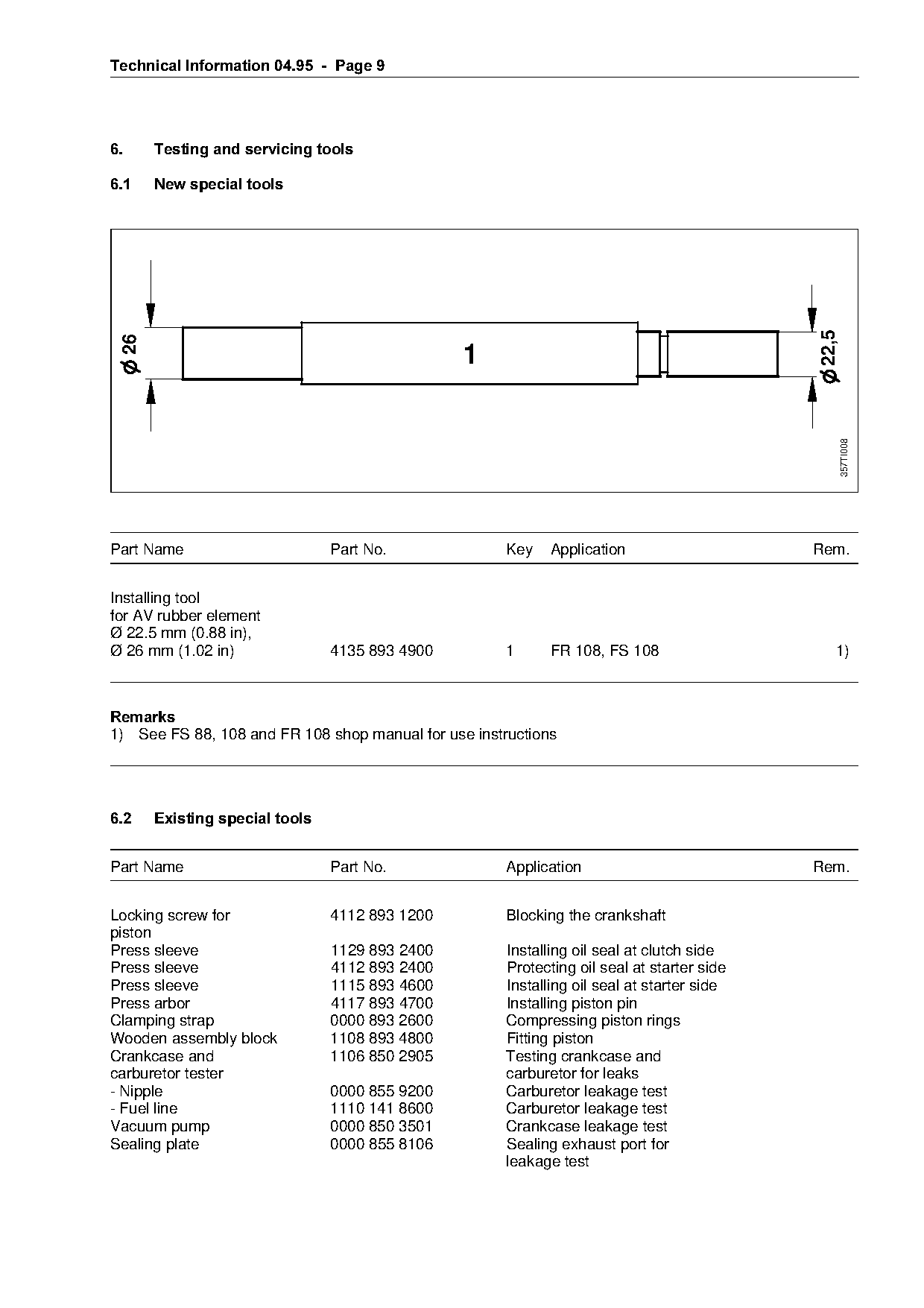
6.1===New special tools

                                                                                            22,5
 26


                                                                                                   357TI008
Part Name                      Part No.               Key fo Application                    Rem.
Installing tool
for AV rubber element
Ø 22.5 mm (0.88 in),

Ø 26 mm (1.02 in)              4135 893 4900          1      FR 108, FS 108                    1)

5HPDUNV
1) See FS 88, 108 and FR 108 shop manual for use instructions

6.2===Existing special tools

Part Name                      Part No.               Application                           Rem.

Locking screw for              4112 893 1200          Blocking the crankshaft
piston
Press sleeve                   1129 893 2400          Installing oil seal at clutch side

Press sleeve                   4112 893 2400          Protecting oil seal at starter side
Press sleeve                   1115 893 4600          Installing oil seal at starter side
Press arbor                    4117 893 4700          Installing piston pin
Clamping strap                 0000 893 2600          Compressing piston rings
Wooden assembly block          1108 893 4800          Fitting piston
Crankcase and                  1106 850 2905          Testing crankcase and
carburetor tester                                     carburetor for leaks
- Nipple                       0000 855 9200          Carburetor leakage test
- Fuel line                    1110 141 8600          Carburetor leakage test
Vacuum pump                    0000 850 3501          Crankcase leakage test
Sealing plate                  0000 855 8106          Sealing exhaust port for
                                                      leakage test
Page 10 of 11
Text of page 10 — search, copy, screen readers
Technical Information 04.95  -  Page 10

6.2====Existing special tools =cont¶G

Part Name                       Part No.                   Application                                             R

Test flange                     1113 850 4200              Leakage test                                 1)
Setting gauge                   1111 890 6400              Setting air gap between ignition module
                                                           and flywheel                                            2
Puller                          0000 890 4400              Removing oil seals
- Jaws (profile 3.1)            0000 893 3706
Installing tool 10              5910 890 2210              Fitting hookless snap rings in piston
Removing tool                   4119 890 4600              Removing crankshaft (starter side)           3)

Socket, 13 mm                   5910 893 5608              Crankshaft nut (carrier, flywheel)

Torque wrench                   5910 890 0301              Screwed assemblies (0.5 to 18 Nm)
                                5910 890 0302                                                           4)
Torque wrench                   5910 890 0311              Screwed assemblies (6 to 80 Nm)

                                5910 890 0312                                                           4)
Assembly hook                   5910 893 8800              Removing pickup body
T-handle screwdriver            5910 890 2400              IS spline screws
QI-T27x150

Crimping tool                   5910 890 8210              Wire connectors, lugs, etc.
Assembly stand                  5910 850 3100              Holds powerhead in position for repairs
- Flange
- Clamping plate
                                5910 893 2500
                                5910 890 2100
                                                           Settings as for FS 106 or FS 108
Socket                          0812 542 2104              Cylinder base screws
Press arbor                     4119 893 7200              Removing and installing main bearings
Pliers C19                      0811 641 8380              Internal circlips (gearhead)                 5)
Pliers A10                      0811 611 8200              External circlips (clutch drum,

                                                           gearhead, drive pinion)
Circlip pliers                  0816 610 1495              External circlips (clutch drum)
Press arbor                     1108 893 4700              Removing clutch drum
Press arbor                     1118 893 7200              Removing and installing ball bearing in

                                                           clutch housing

5HPDUNV

1) Flange 1128 850 4200 may be used as an alternative.
2) Setting gauge 4118 890 6401 may be used as an alternative.
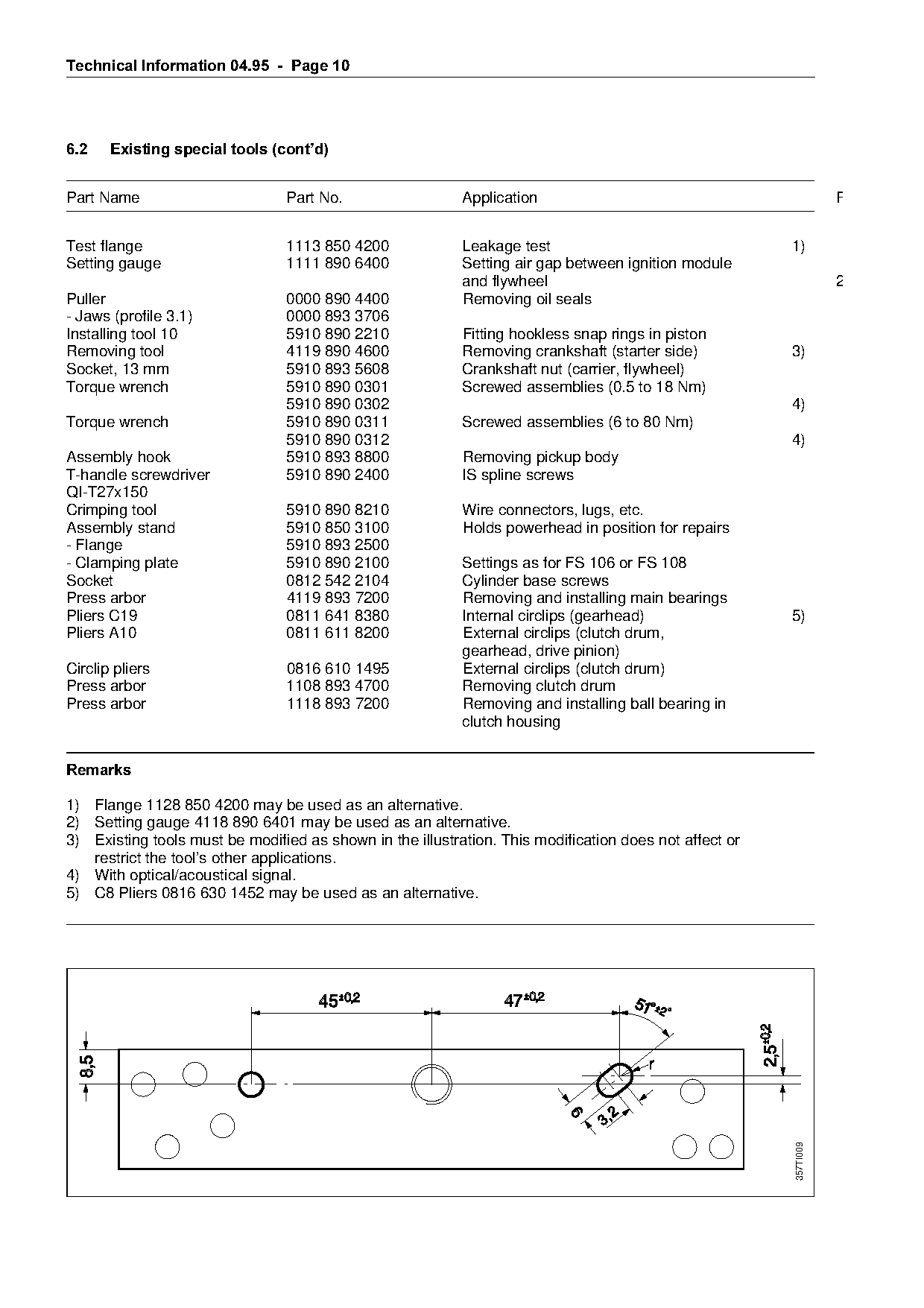
3) Existing tools must be modified as shown in the illustration. This modification does not affect or

   restrict the tool’s other applications.
4) With optical/acoustical signal.
5) C8 Pliers 0816 630 1452 may be used as an alternative.

                                                                                                        357TI009
Page 11 of 11
Text of page 11 — search, copy, screen readers
Technical Information 04.95 - Page 11
7.====Important=======================================`ode Repair procedure FS 88
FS 108
If the unit is started up in the course of repairs ===============================================co=NMU
or maintenance work, it is essential to strictly
observe all local and national safety regulations=====N====`r~nkc~seI=phort=_lock===================OKN
as well as the safety precautions outlined in
the owner¶s manual.===================================O====`rankshaft and/or Bearings 2.2
3 Crankcase Gasket, Sealing 2.0
8.====Service note
4 Crankshaft seals 0.7
Refer to the service manual for servicing and 5 Cylinder and/or Piston 0.8
repair procedures on the FR 108.
For the first time ever the new service manual for 6 Ignition 0.5
this brushcutter does not include the chapters
"Servicing the Carburetor", "Troubleshooting" or 7 Fuel Hose, Fuel Supply 0.5
other standard repair jobs. These servicing and
8 Gear Box, Arbor Assy 0.6
repair procedures are described in a separate
handbook which will be available in the foreseeable 9 Carburetor 0.7
future. The appropriate chapters in the service
manual for models FR and FS 106 can be used as 10 Fan Housing, Clutch Housing 0.8
a reference until the new handbook is published.
11 Front Handle, Throttle 0.6
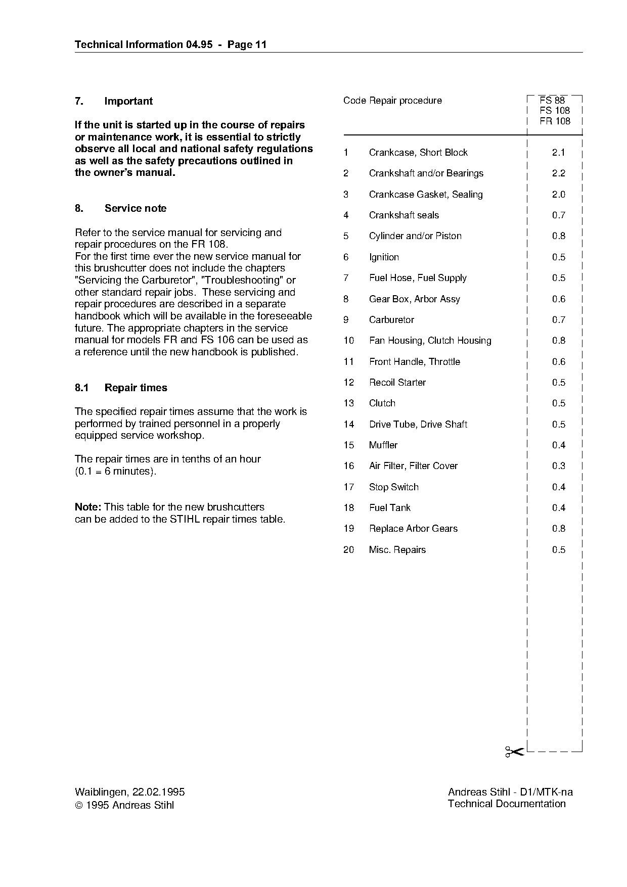
8.1===Repair times
12
Recoil Starter 0.5
13 Clutch 0.5
The specified repair times assume that the work is
performed by trained personnel in a properly 14 Drive Tube, Drive Shaft 0.5
equipped service workshop.
15 Muffler 0.4
The repair times are in tenths of an hour
16 Air Filter, Filter Cover 0.3
(0.1 = 6 minutes).
17 Stop Switch 0.4
Note:=qhis table for the new brushcutters 18 Fuel Tank 0.4
can be added to the STIHL repair times table.
19 Replace Arbor Gears 0.8
20 Misc. Repairs 0.5
✂
Waiblingen, 22.02.1995 Andreas Stihl - D1/MTK-na
1995 Andreas Stihl Technical Documentation Most of these PDFs embed fonts with a shifted character map, so the text above was recovered rather than copied — read it as a faithful but imperfect transcription, and treat the page image above each block as the authority where the two disagree — the figures exist only there, because they are vector drawings that text extraction cannot keep.