Technical Information · issue 7 of 1995
Flywheel; carburetor; wiring harness; front handle
Model 044 artic=ch~in=s~ws=from=m~chine=number=X 30 991 112=will=be=equipped=with=he~ted=h~ndles=in
Part changes (3)
| Was | Becomes | What the bulletin says |
|---|---|---|
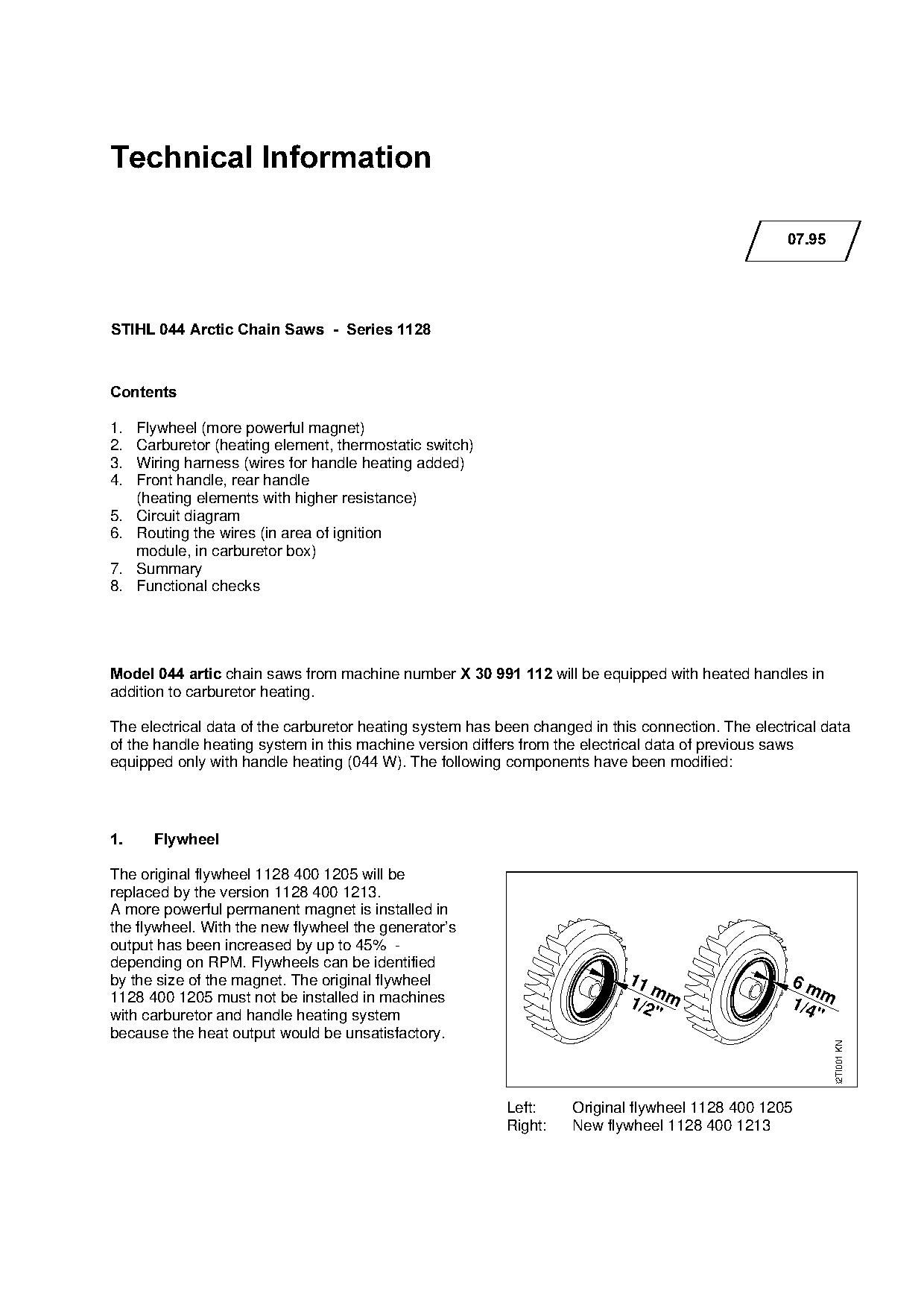
| 1128 400 1205 | 1128 400 1213 | The original flywheel 1128 400 1205 will be replaced by the version 1128 400 1213. |
| 1128 430 0500 | 1128 430 0501 | The original thermostatic switch 1128 430 0500 will be replaced by the new version 1128 430 0501. |
| 1128 790 1705 | 1128 790 1707 | The original front handle 1128 790 1705 has been replaced by the new version 1128 790 1707. |
Full text
Page 1 of 6
Text of page 1 — search, copy, screen readers
Technical Information

                                                                                                   07.95

STIHL 044 Arctic Chain Saws  -  Series 1128

&RQWHQWV

1.   Flywheel (more powerful magnet)

2.   Carburetor (heating element, thermostatic switch)
3.   Wiring harness (wires for handle heating added)
4.   Front handle, rear handle

     (heating elements with higher resistance)
5.   Circuit diagram
6.   Routing the wires (in area of ignition

7.
     module, in carburetor box)
     Summary
8.   Functional checks

Model 044 artic=chain saws from machine number X 30 991 112=will be equipped with heated handles in
addition to carburetor heating.

The electrical data of the carburetor heating system has been changed in this connection. The electrical data

of the handle heating system in this machine version differs from the electrical data of previous saws
equipped only with handle heating (044 W). The following components have been modified:

1.=====Flywheel

The original flywheel 1128 400 1205 will be
replaced by the version 1128 400 1213.

A more powerful permanent magnet is installed in
the flywheel. With the new flywheel the generator’s
output has been increased by up to 45% -

depending on RPM. Flywheels can be identified
by the size of the magnet. The original flywheel                            11                      6m
                                                                               m                         m
1128 400 1205 must not be installed in machines                             1/2 m                   1/4
with carburetor and handle heating system                                      "                        "
because the heat output would be unsatisfactory.
                                                                                                             32TI001 KN

                                                          Left:     Original flywheel 1128 400 1205
                                                          Right:    New flywheel 1128 400 1213
Page 2 of 6
Text of page 2 — search, copy, screen readers
Technical Information 07.95 - Page 2
2.======Carburetor
The original `PjJp=23=carburetor will be replaced by
the `PjJp=24=carburetor. The differences between
the two carburetors are the heating element and
thermostatic switch.
2.1.====Heating element
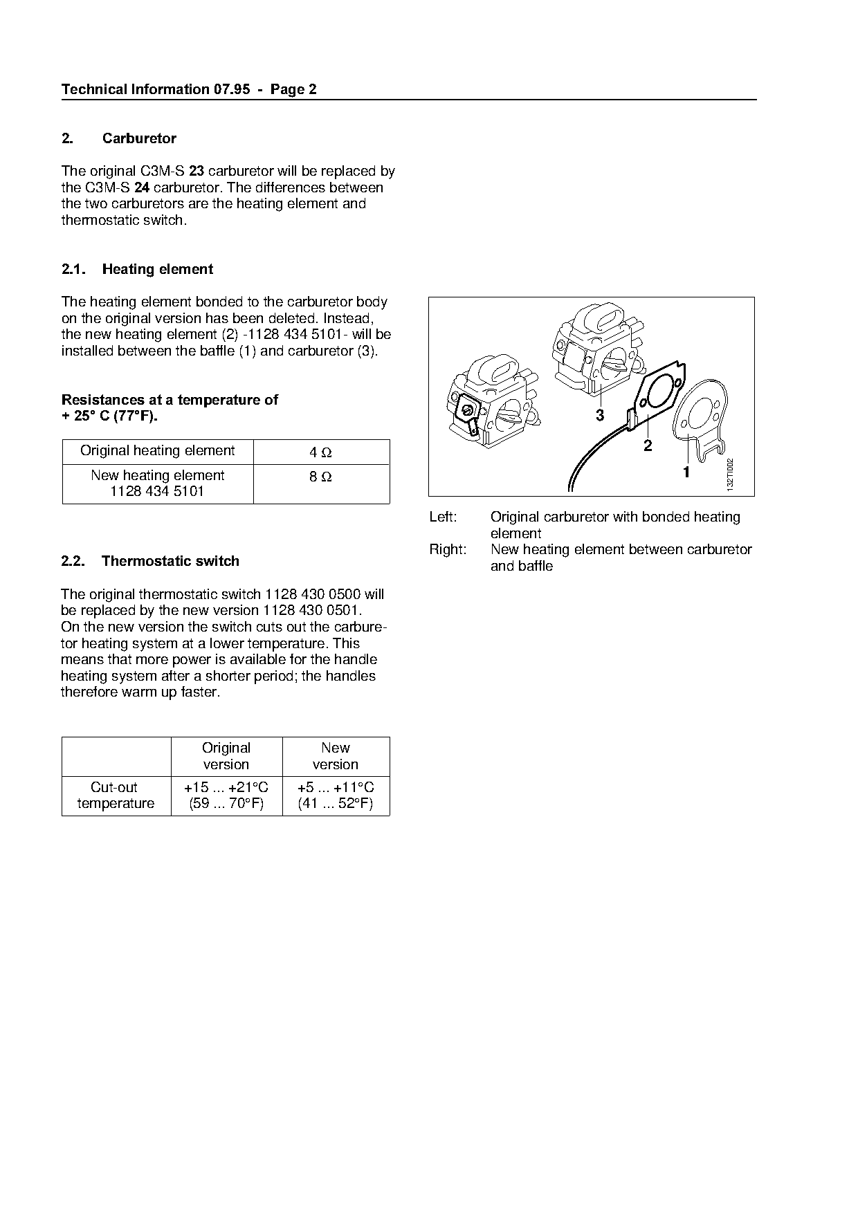
The heating element bonded to the carburetor body
on the original version has been deleted. Instead,
the new heating element (2) -1128 434 5101- will be
installed between the baffle (1) and carburetor (3).
Resistances at a temperature of
+ 25 C =77F=.===================================================================P
Original heating element 4Ω 2
132TI002
New heating element 8Ω 1
1128 434 5101
Left: fo
Original carburetor with bonded heating
element
Right: New heating element between carburetor
2.2.====Thermostatic switch========================================~nd baffle
The original thermostatic switch 1128 430 0500 will
be replaced by the new version 1128 430 0501.
On the new version the switch cuts out the carbure-
tor heating system at a lower temperature. This
means that more power is available for the handle
heating system after a shorter period; the handles
therefore warm up faster.
Original New
version version
Cut-out +15 ... +21°C +5 ... +11°C
temperature (59 ... 70°F) (41 ... 52°F) Page 3 of 6
Text of page 3 — search, copy, screen readers
Technical Information 07.95 - Page 3
3.=======Wiring harness
Wires for the handle heating system have
been added to the original wiring harness
1128 440 3007. The part number of the new wiring
harness is 1128 440 3012.
4.=======Front handle, rear handle
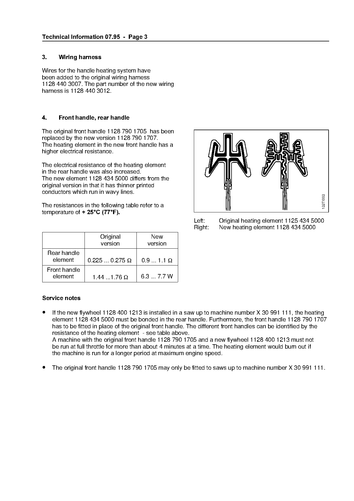
The original front handle 1128 790 1705 has been
replaced by the new version 1128 790 1707.
The heating element in the new front handle has a
higher electrical resistance.
The electrical resistance of the heating element
in the rear handle was also increased.
The new element 1128 434 5000 differs from the
original version in that it has thinner printed
conductors which run in wavy lines.
132TI003
The resistances in the following table refer to a
temperature of + 25C =77F=.==================================fo
Left: Original heating element 1125 434 5000
Right: New heating element 1128 434 5000
Original New
version version
Rear handle
element 0.225 ... 0.275 Ω 0.9 ... 1.1 Ω
Front handle
element 1.44 ...1.76 Ω 6.3 ... 7.7 W
Service notes
• If the new flywheel 1128 400 1213 is installed in a saw up to machine number X 30 991 111, the heating
element 1128 434 5000 must be bonded in the rear handle. Furthermore, the front handle 1128 790 1707
has to be fitted in place of the original front handle. The different front handles can be identified by the
resistance of the heating element - see table above.
A machine with the original front handle 1128 790 1705 and a new flywheel 1128 400 1213 must not
be run at full throttle for more than about 4 minutes at a time. The heating element would burn out if
the machine is run for a longer period at maximum engine speed.
• The original front handle 1128 790 1705 may only be fitted to saws up to machine number X 30 991 111. Page 4 of 6
Text of page 4 — search, copy, screen readers
Technical Information 07.95  -  Page 4

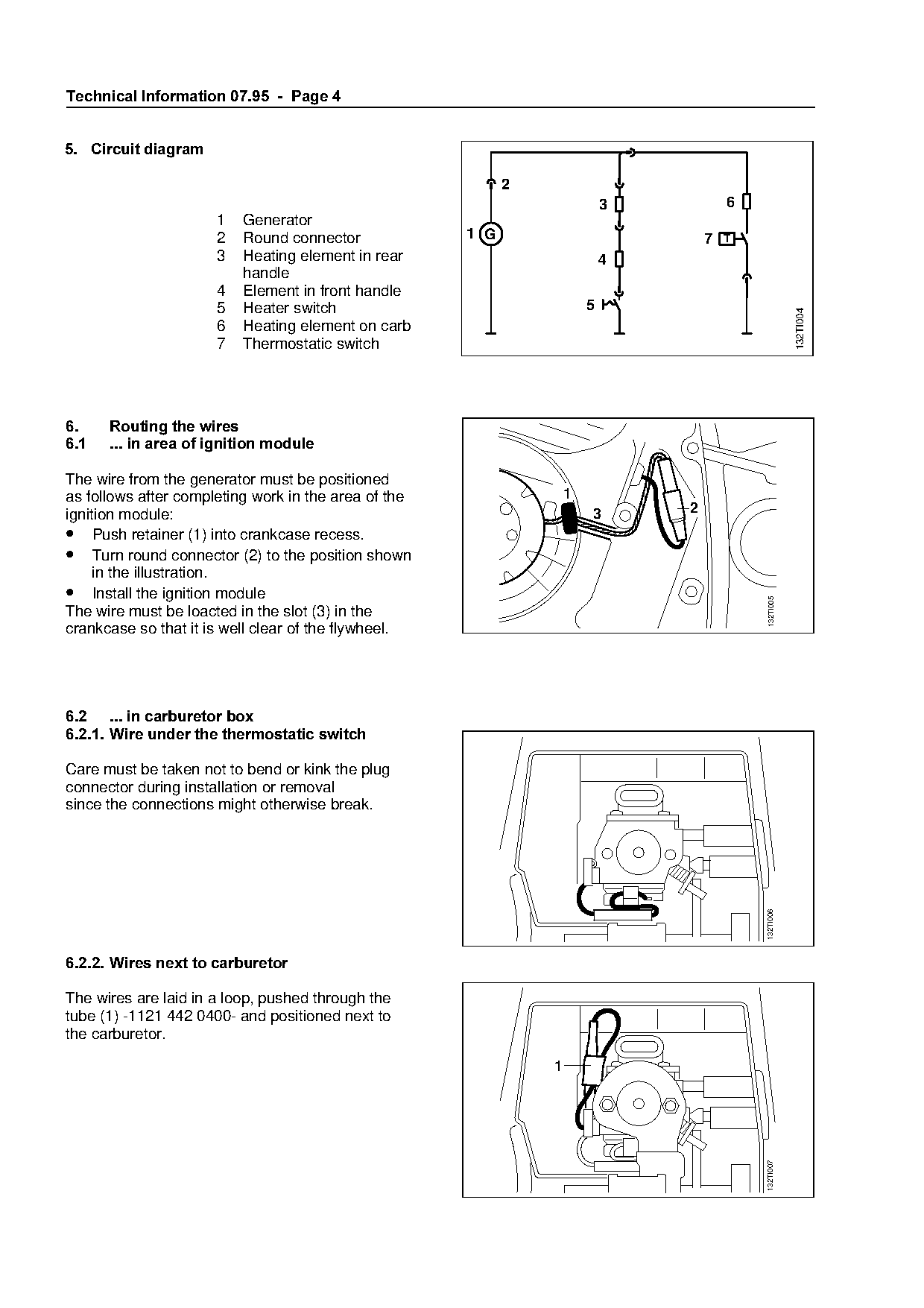
5.=Circuit diagram

                                                             2
                                                                              3              6
                      1   Generator
                      2   Round connector              1 G                               7   T
                      3   Heating element in rear                             4
                          handle
                      4   Element in front handle
                      5   Heater switch                                   5

                                                                                                            132TI004
                      6   Heating element on carb
                      7   Thermostatic switch

6.====Routing the wires

6.1===... in area of ignition module

The wire from the generator must be positioned

as follows after completing work in the area of the                   1
ignition module:                                                          3          2
• Push retainer (1) into crankcase recess.
• Turn round connector (2) to the position shown
     in the illustration.
• Install the ignition module

                                                                                                 132TI005
The wire must be loacted in the slot (3) in the
crankcase so that it is well clear of the flywheel.

6.2=... in carburetor box
6.2.1.=Wire under the thermostatic switch

Care must be taken not to bend or kink the plug
connector during installation or removal

since the connections might otherwise break.

                                                                                                 132TI006

6.2.2.=Wires next to carburetor

The wires are laid in a loop, pushed through the
tube (1) -1121 442 0400- and positioned next to
the carburetor.

                                                                  1
                                                                                                 132TI007
Page 5 of 6
Text of page 5 — search, copy, screen readers
Technical Information 07.95  -  Page 5

7.=Summary

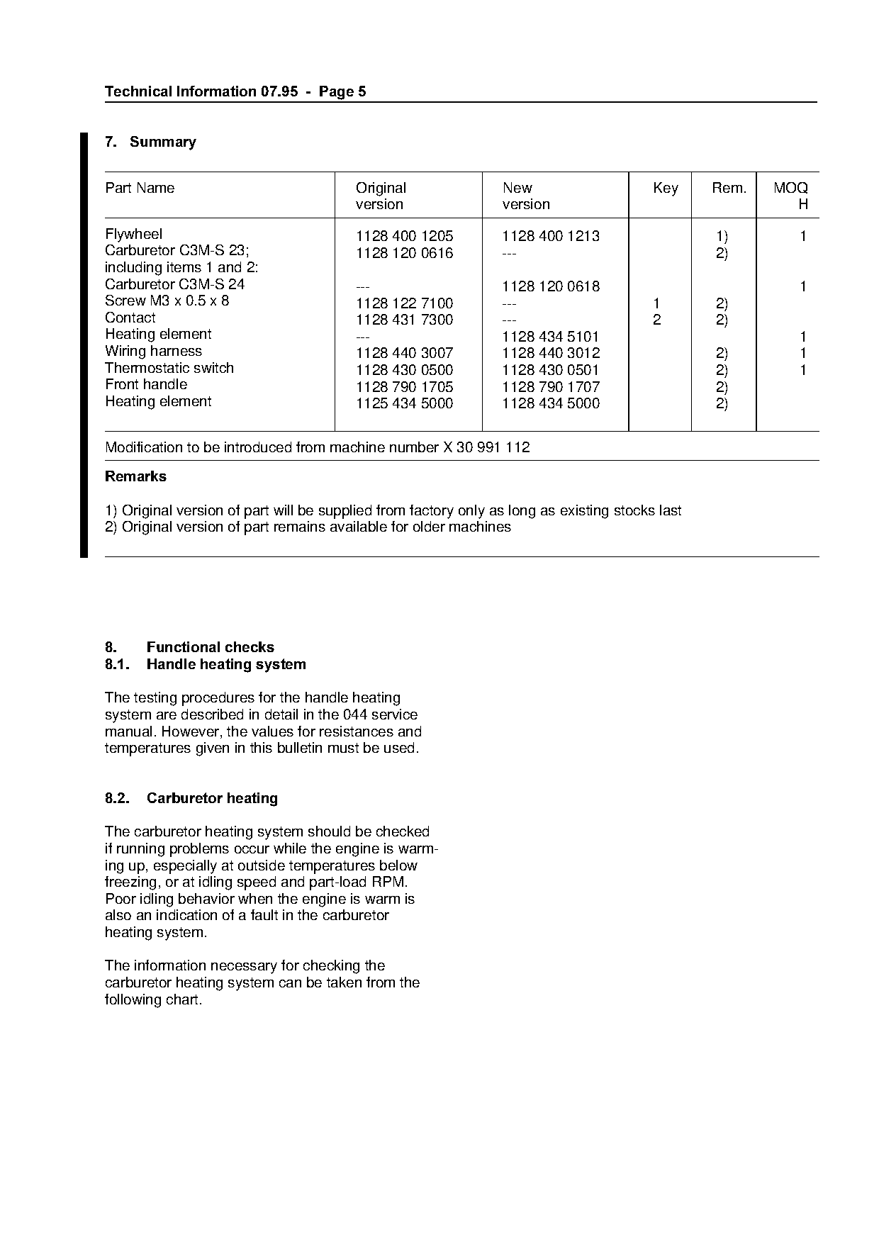
Part Name                               Original                New                      Key     Rem.   MOQ
                                        version                 version                                   H
Flywheel                                1128 400 1205           1128 400 1213                    1)       1
Carburetor C3M-S 23;                    1128 120 0616           ---                              2)
including items 1 and 2:
Carburetor C3M-S 24                     ---                     1128 120 0618                             1
Screw M3 x 0.5 x 8                      1128 122 7100           ---                      1       2)
Contact                                 1128 431 7300           ---                      2       2)
Heating element                         ---                     1128 434 5101                             1

Wiring harness                          1128 440 3007           1128 440 3012                    2)       1

Thermostatic switch                     1128 430 0500           1128 430 0501                    2)       1
Front handle                            1128 790 1705           1128 790 1707                    2)
Heating element                         1125 434 5000           1128 434 5000                    2)

Modification to be introduced from machine number X 30 991 112

5HPDUNV

1) Original version of part will be supplied from factory only as long as existing stocks last
2) Original version of part remains available for older machines

8. ====Functional checks
8.1.===Handle heating system

The testing procedures for the handle heating

system are described in detail in the 044 service
manual. However, the values for resistances and
temperatures given in this bulletin must be used.

8.2. =Carburetor heating

The carburetor heating system should be checked
if running problems occur while the engine is warm-

ing up, especially at outside temperatures below
freezing, or at idling speed and part-load RPM.
Poor idling behavior when the engine is warm is

also an indication of a fault in the carburetor
heating system.

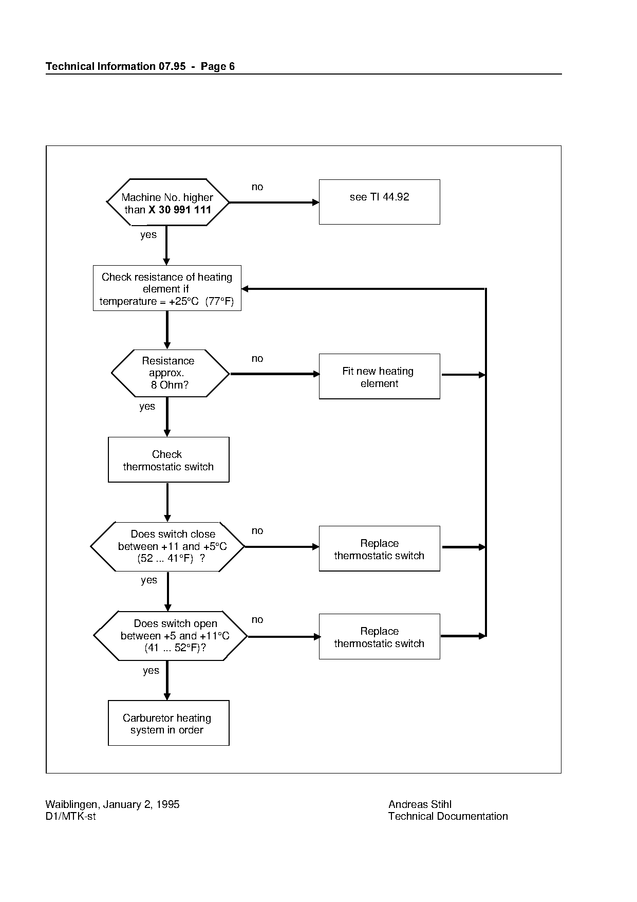
The information necessary for checking the
carburetor heating system can be taken from the
following chart.
Page 6 of 6
Text of page 6 — search, copy, screen readers
Technical Information 07.95  -  Page 6

               Machine No. higher                    see TI 44.92
               than X 30 991 111

                   yes

           Check resistance of heating
                   element if
          temperature = +25°C (77°F)

                   Resistance            no
                                                   Fit new heating
                    approx.
                    8 Ohm?
                                                      foelement

                  yes

                    Check
               thermostatic switch

                Does switch close        no
              between +11 and +5°C                     Replace

                  (52 ... 41°F) ?                 thermostatic switch

                   yes

                 Does switch open        no

               between +5 and +11°C                    Replace
                   (41 ... 52°F)?                 thermostatic switch

                   yes

               Carburetor heating
                system in order

Waiblingen, January 2, 1995                                  Andreas Stihl
D1/MTK-st                                                    Technical Documentation
Most of these PDFs embed fonts with a shifted character map, so the text above was recovered rather than copied — read it as a faithful but imperfect transcription, and treat the page image above each block as the authority where the two disagree — the figures exist only there, because they are vector drawings that text extraction cannot keep.