Technical Information · issue 9 of 1995
Quickstop auger brake
Model BT 106 Earth Augers - Series 4311
IssueTI 9/1995
Full text
Page 1 of 5
Text of page 1 — search, copy, screen readers
Technical Information

                                                                       09.95

Model BT 106 Earth Augers  -  Series 4311

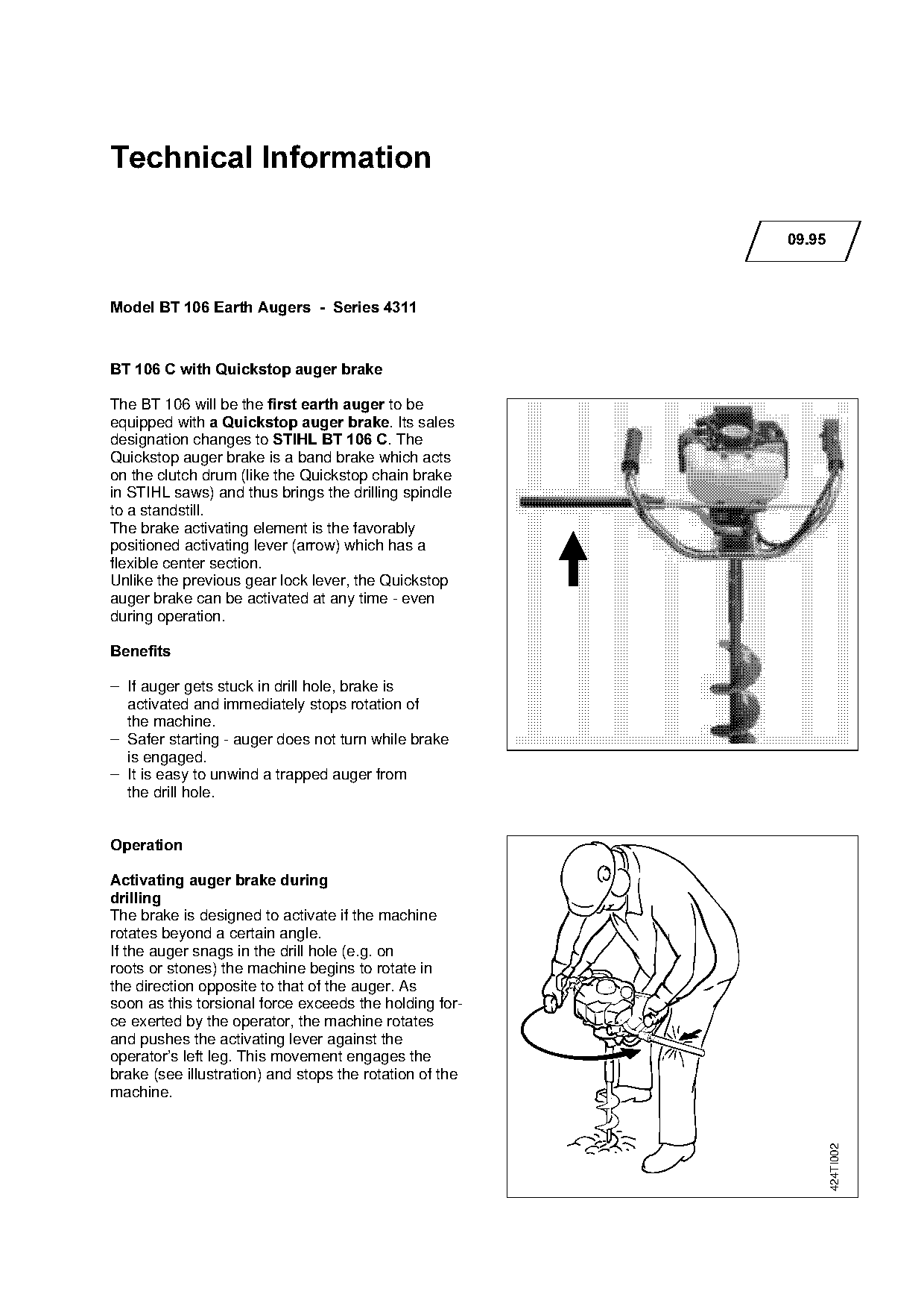
BT 106 C with Quickstop auger brake

The BT 106 will be the first earth auger=to be
equipped with a Quickstop auger brakeK=fts sales
designation changes to STIHL BT 106 CK=qhe

Quickstop auger brake is a band brake which acts
on the clutch drum (like the Quickstop chain brake
in STIHL saws) and thus brings the drilling spindle

to a standstill.
The brake activating element is the favorably
positioned activating lever (arrow) which has a
flexible center section.
Unlike the previous gear lock lever, the Quickstop
auger brake can be activated at any time - even
during operation.

%HQHILWV

– If auger gets stuck in drill hole, brake is
  activated and immediately stops rotation of

  the machine.

– Safer starting - auger does not turn while brake
  is engaged.
– It is easy to unwind a trapped auger from
  the drill hole.

2SHUDWLRQ

Activating auger brake during
GULOOLQJ

The brake is designed to activate if the machine
rotates beyond a certain angle.
If the auger snags in the drill hole (e.g. on

roots or stones) the machine begins to rotate in
the direction opposite to that of the auger. As
soon as this torsional force exceeds the holding for-
ce exerted by the operator, the machine rotates
and pushes the activating lever against the
operator’s left leg. This movement engages the
brake (see illustration) and stops the rotation of the
machine.
                                                                               424TI002
Page 2 of 5
Text of page 2 — search, copy, screen readers
Technical Information 09.95  -  Page 2

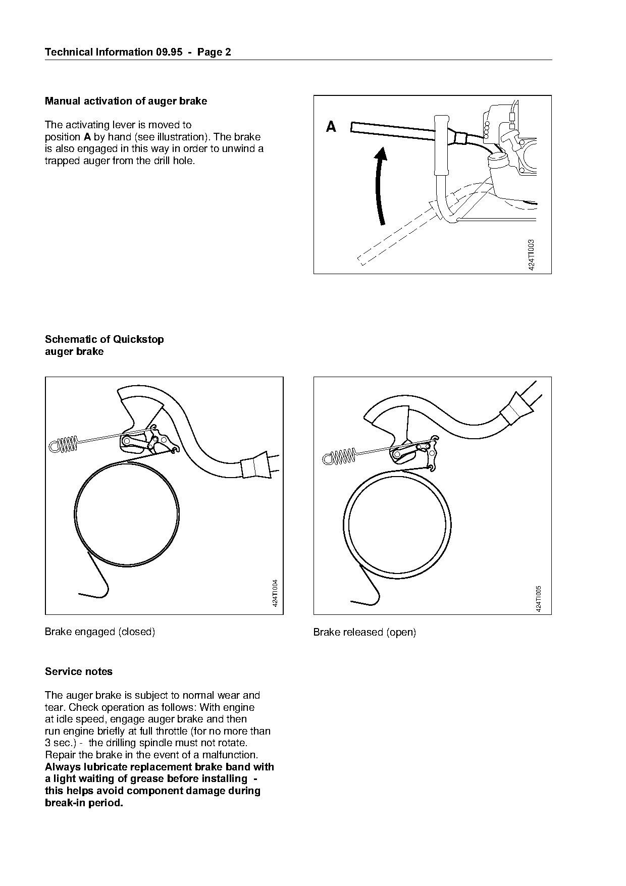
Manual activation of auger brake

The activating lever is moved to                                 A
position $ by hand (see illustration). The brake
is also engaged in this way in order to unwind a
trapped auger from the drill hole.

                                                                                              424TI003
Schematic of Quickstop
auger brake

                                                    424TI004

                                                                                                         424TI005

Brake engaged (closed)                                         Brake released (open)

Service notes

The auger brake is subject to normal wear and
tear. Check operation as follows: With engine
at idle speed, engage auger brake and then
run engine briefly at full throttle (for no more than
3 sec.) - the drilling spindle must not rotate.
Repair the brake in the event of a malfunction.
Always lubricate replacement brake band with
a light waiting of grease before installing  -
this helps avoid component damage during
break-in period.
Page 3 of 5
Text of page 3 — search, copy, screen readers
Technical Information 09.95  -  Page 3

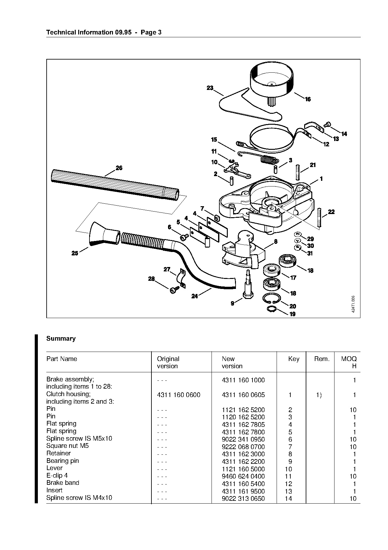
                                                                                   424TI.006

6XPPDU\

Part Name                           Original        New             Key   Rem.   MOQ
                                    version         version                        H
Brake assembly;                     ---             4311 160 1000                     1

including items 1 to 28:
Clutch housing;                     4311 160 0600   4311 160 0605   1     1)          1
including items 2 and 3:

Pin                                 ---             1121 162 5200    2            10
Pin                                 ---             1120 162 5200    3             1
Flat spring                         ---             4311 162 7805    4             1
Flat spring                         ---             4311 162 7800    5             1
Spline screw IS M5x10               ---             9022 341 0950    6            10
Square nut M5                       ---             9222 068 0700    7            10
Retainer                            ---             4311 162 3000    8             1
Bearing pin                         ---             4311 162 2200    9             1
Lever                               ---             1121 160 5000   10             1
E-clip 4                            ---             9460 624 0400   11            10
Brake band                          ---             4311 160 5400   12             1
Insert                              ---             4311 161 9500   13             1
Spline screw IS M4x10               ---             9022 313 0650   14            10
Page 4 of 5
Text of page 4 — search, copy, screen readers
Technical Information 09.95  -  Page 4

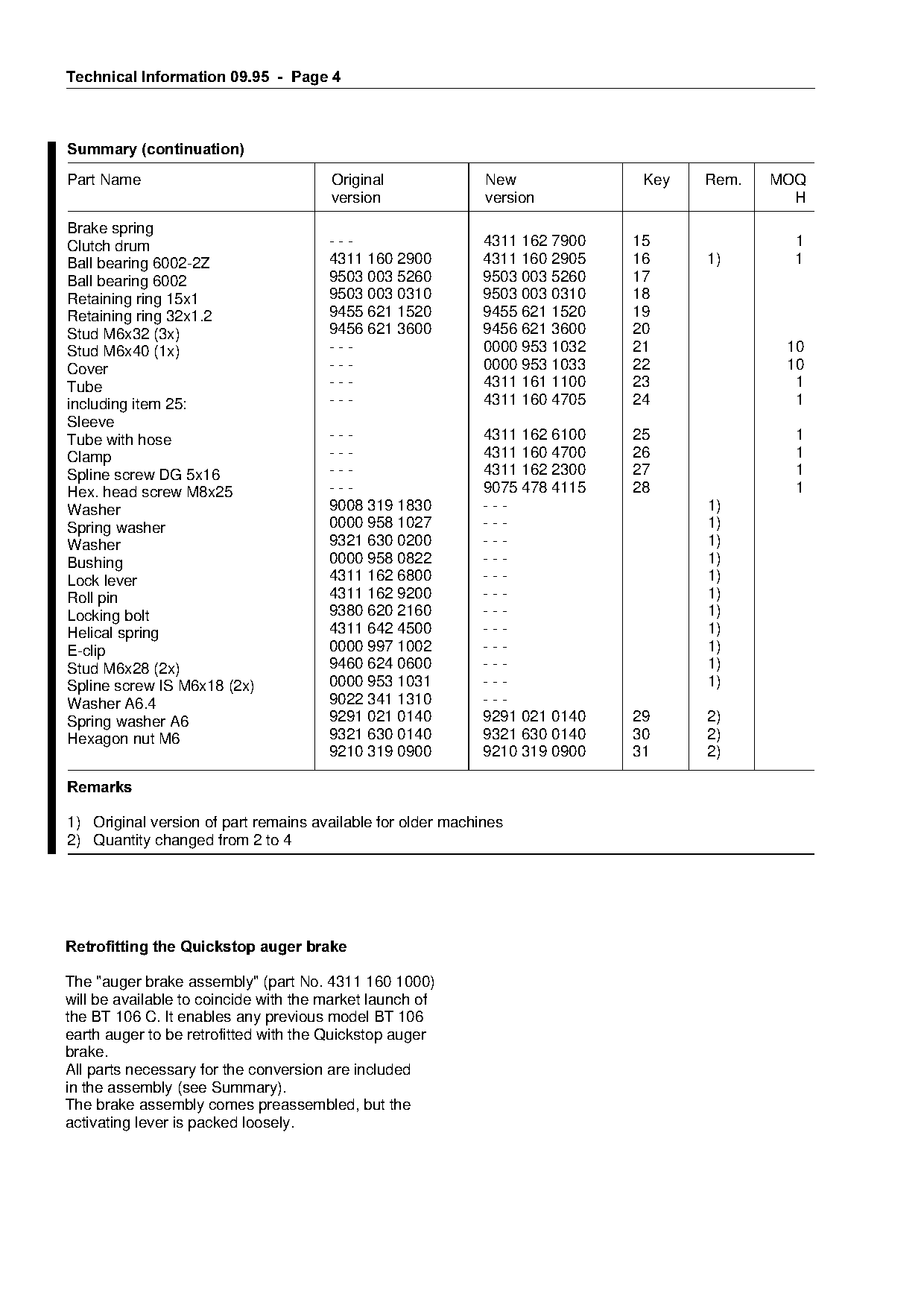
Summary =continuation
Part Name                              Original              New              Key   Rem.   MOQ
                                       version               version                         H

Brake spring
Clutch drum                            ---                   4311 162 7900   15              1
Ball bearing 6002-2Z                   4311 160 2900         4311 160 2905   16     1)       1
Ball bearing 6002                      9503 003 5260         9503 003 5260   17
Retaining ring 15x1                    9503 003 0310         9503 003 0310   18
Retaining ring 32x1.2                  9455 621 1520         9455 621 1520   19
Stud M6x32 (3x)                        9456 621 3600         9456 621 3600   20
Stud M6x40 (1x)                        ---                   0000 953 1032   21             10
                                       ---                   0000 953 1033   22             10

Cover

Tube                                   ---                   4311 161 1100   23              1
including item 25:                     ---                   4311 160 4705   24              1
Sleeve
                                       ---                   4311 162 6100   25              1

Tube with hose
Clamp                                  ---                   4311 160 4700   26              1
Spline screw DG 5x16                   ---                   4311 162 2300   27              1
Hex. head screw M8x25                  ---                   9075 478 4115   28              1

Washer                                 9008 319 1830         ---                    1)
Spring washer                          0000 958 1027         ---                    1)
                                       9321 630 0200         ---                    1)
Washer
Bushing                                0000 958 0822
                                       4311 162 6800
                                                             ---
                                                             ---
                                                                   fo               1)
                                                                                    1)
Lock lever
                                       4311 162 9200         ---                    1)
Roll pin
Locking bolt                           9380 620 2160         ---                    1)
Helical spring                         4311 642 4500         ---                    1)

E-clip                                 0000 997 1002         ---                    1)
Stud M6x28 (2x)                        9460 624 0600         ---                    1)
Spline screw IS M6x18 (2x)             0000 953 1031         ---                    1)
Washer A6.4                            9022 341 1310         ---

Spring washer A6                       9291 021 0140         9291 021 0140   29     2)
                                       9321 630 0140         9321 630 0140   30     2)

Hexagon nut M6
                                       9210 319 0900         9210 319 0900   31     2)

5HPDUNV

1) Original version of part remains available for older machines
2) Quantity changed from 2 to 4

Retrofitting the Quickstop auger brake

The "auger brake assembly" (part No. 4311 160 1000)
will be available to coincide with the market launch of
the BT 106 C. It enables any previous model BT 106
earth auger to be retrofitted with the Quickstop auger
brake.
All parts necessary for the conversion are included
in the assembly (see Summary).
The brake assembly comes preassembled, but the
activating lever is packed loosely.
Page 5 of 5
Text of page 5 — search, copy, screen readers
Technical Information 09.95 - Page 5
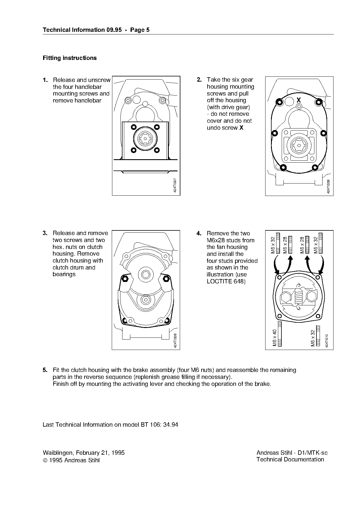
Fitting instructions
1.=oelease and unscrew 2.=q~ke the six gear
the four handlebar housing mounting
mounting screws and screws and pull
remove handlebar off the housing X
(with drive gear)
- do not remove
cover and do not
undo screw ;
424TI007
424TI008
3.=oelease and remove 4.=oemove the two
M6 x 28
M6 x 32
M6 x 32
M6 x 28
two screws and two M6x28 studs from
hex. nuts on clutch the fan housing
housing. Remove and install the
clutch housing with four studs provided
clutch drum and as shown in the
bearings illustration (use
LOCTITE 648)
M6 x 40
M6 x 32
424TI009
424TI010
5.=cit the clutch housing with the brake assembly (four M6 nuts) and reassemble the remaining
parts in the reverse sequence (replenish grease filling if necessary).
Finish off by mounting the activating lever and checking the operation of the brake.
Last Technical Information on model BT 106: 34.94
Waiblingen, February 21, 1995 Andreas Stihl - D1/MTK-sc
1995 Andreas Stihl Technical Documentation Most of these PDFs embed fonts with a shifted character map, so the text above was recovered rather than copied — read it as a faithful but imperfect transcription, and treat the page image above each block as the authority where the two disagree — the figures exist only there, because they are vector drawings that text extraction cannot keep.