Technical Information · issue 15 of 1995
Carburetor; Shroud
IssueTI 15/1995
Full text
Page 1 of 11
Text of page 1 — search, copy, screen readers
Technical Information

                                                                                       15.95

Brushcutters===============FS 108  -  Series 4135
    =======================FR 108  -  Series 4135

Engineering Changes to Comply with Emissons Regulations
see also TI 41.94 and 47.94

&RQWHQWV

1.        Carburetor
1.1       New spare parts
1.2       Service notes
1.2.1
1.3
          Setting instructions for service
          Setting instructions for user
2.        Shroud (symbols for setting carburetor)

1.=Carburetor

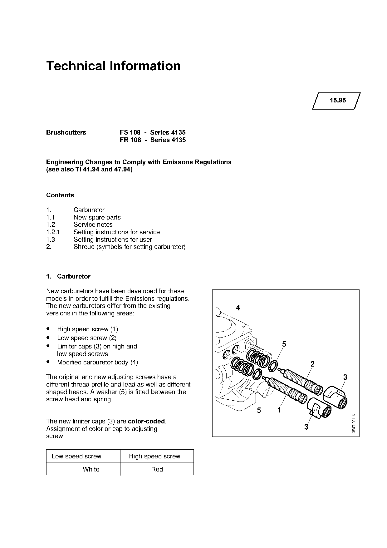
New carburetors have been developed for these

models in order to fulfill the Emissions regulations.
The new carburetors differ from the existing                  4

versions in the following areas:

• High speed screw (1)
• Low speed screw (2)

• Limiter caps (3) on high and                                             5
     low speed screws

•    Modified carburetor body (4)                                                  2
The original and new adjusting screws have a                                               3

different thread profile and lead as well as different
shaped heads. A washer (5) is fitted between the
screw head and spring.

                                                                  5    1
                                                                                               354TI001 K

The new limiter caps (3) are color-coded.
Assignment of color or cap to adjusting                                        3
screw:

    Low speed screw           High speed screw

             White                     Red
Page 2 of 11
Text of page 2 — search, copy, screen readers
Technical Information 15.95  -  Page 2

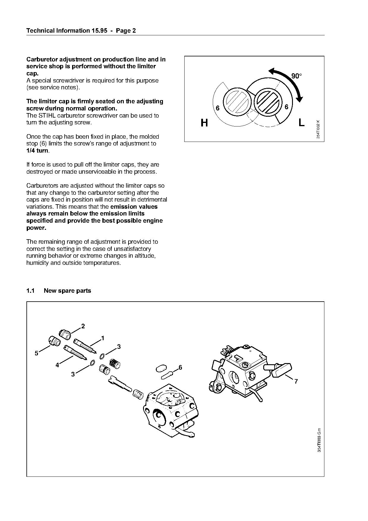
Carburetor adjustment on production line and in
service shop is performed without the limiter
cap.
                                                                                    90°
A special screwdriver is required for this purpose
(see service notes).

The limiter cap is firmly seated on the adjusting
screw during normal operation.======================================6===========6
The STIHL carburetor screwdriver can be used to
turn the adjusting screw.                                       H                       L

                                                                                            354TI002 K
Once the cap has been fixed in place, the molded
stop (6) limits the screw’s range of adjustment to

1/4 turn.

If force is used to pull off the limiter caps, they are
destroyed or made unserviceable in the process.

Carburetors are adjusted without the limiter caps so
that any change to the carburetor setting after the

caps are fixed in position will not result in detrimental
variations. This means that the emission values
always remain below the emission limits
specified and provide the best possible engine
power.
The remaining range of adjustment is provided to
correct the setting in the case of unsatisfactory

running behavior or extreme changes in altitude,
humidity and outside temperatures.

1.1====New spare parts


                              1
                                     3
   5

           4                                                6
                  3
                                                                                    7

                                                                                              354TI003 Gm
Page 3 of 11
Text of page 3 — search, copy, screen readers
Technical Information 15.95  -  Page 3

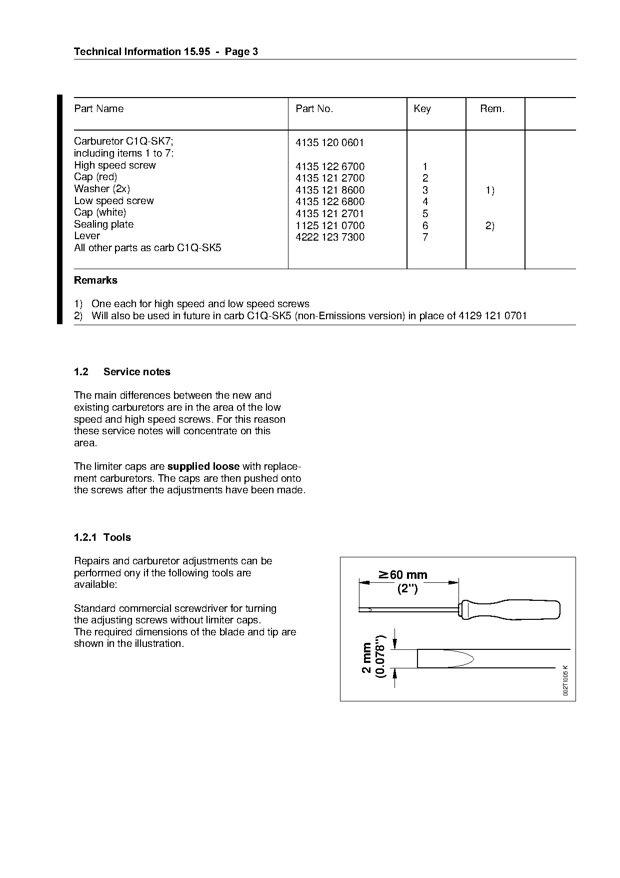
Part Name                                         Part No.                  Key      Rem.

Carburetor C1Q-SK7;                               4135 120 0601
including items 1 to 7:
High speed screw                                  4135 122 6700              1
Cap (red)                                         4135 121 2700              2
Washer (2x)                                       4135 121 8600              3         1)
Low speed screw                                   4135 122 6800              4
Cap (white)                                       4135 121 2701              5
Sealing plate                                     1125 121 0700              6         2)
Lever                                             4222 123 7300              7

All other parts as carb C1Q-SK5

5HPDUNV

1) One each for high speed and low speed screws
2) Will also be used in future in carb C1Q-SK5 (non-Emissions version) in place of 4129 121 0701

1.2===Service notes==========================================fo
The main differences between the new and
existing carburetors are in the area of the low
speed and high speed screws. For this reason

these service notes will concentrate on this
area.

The limiter caps are supplied loose=with replace-

ment carburetors. The caps are then pushed onto
the screws after the adjustments have been made.

1.2.1=Tools

Repairs and carburetor adjustments can be

performed ony if the following tools are                                 60 mm
available:                                                                (2")
Standard commercial screwdriver for turning

the adjusting screws without limiter caps.
The required dimensions of the blade and tip are
                                                              (0.078")

shown in the illustration.

                                                               2 mm

                                                                                                   002TI005 K
Page 4 of 11
Text of page 4 — search, copy, screen readers
Technical Information 15.95  -  Page 4

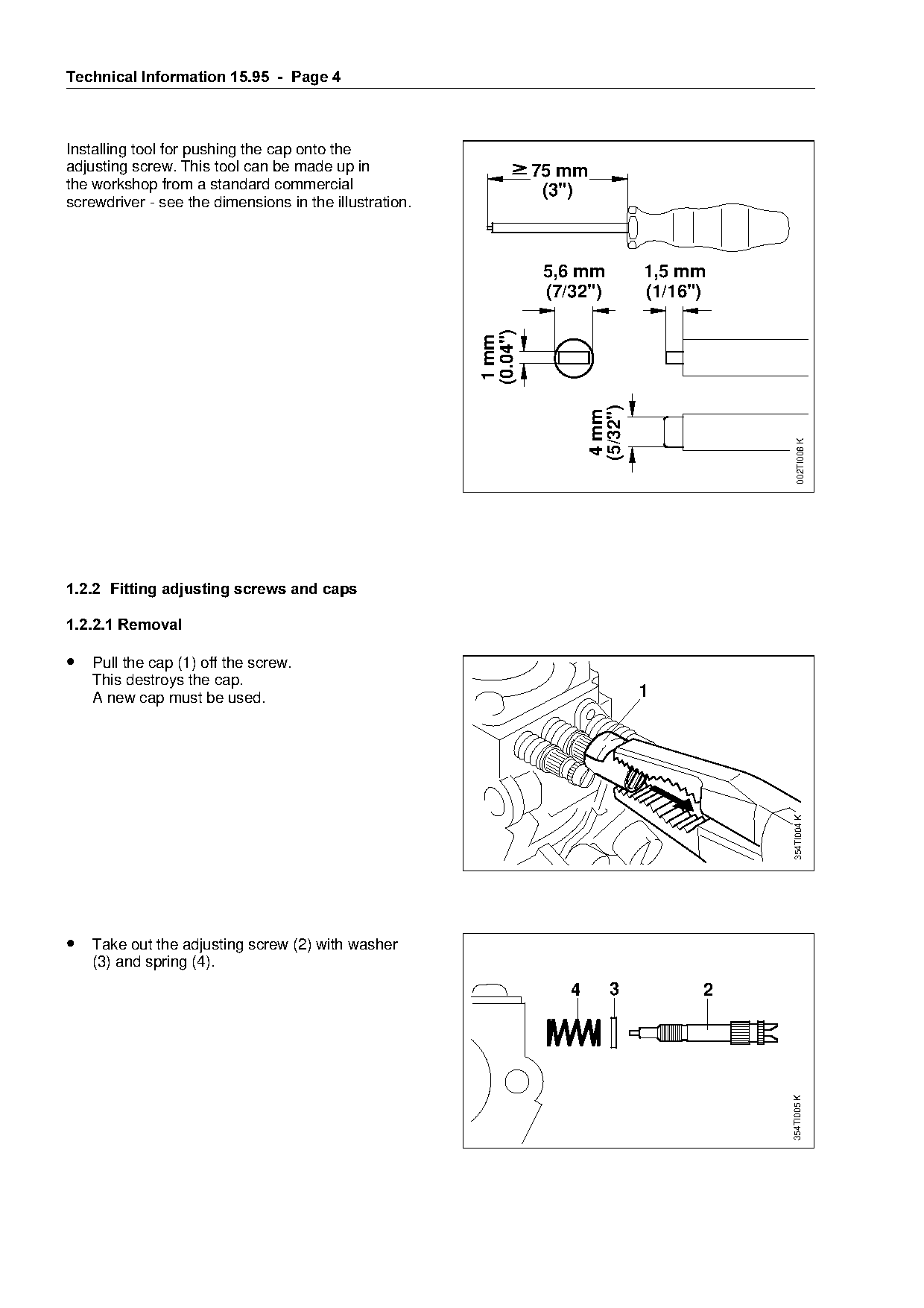
Installing tool for pushing the cap onto the
adjusting screw. This tool can be made up in                       75 mm
the workshop from a standard commercial                             (3")
screwdriver - see the dimensions in the illustration.

                                                                    5,6 mm           1,5 mm
                                                                    (7/32")          (1/16")

                                                         (0.04")
                                                          1 mm

                                                                           (5/32")
                                                                            4 mm

                                                                                                  002TI006 K
1.2.2=Fitting adjusting screws and caps

1.2.2.1 Removal

• Pull the cap (1) off the screw.
    This destroys the cap.
    A new cap must be used.                                                          1

                                                                                               354TI004 K

• Take out the adjusting screw (2) with washer

    (3) and spring (4).
                                                                       4       3           2
                                                                                               354TI005 K
Page 5 of 11
Text of page 5 — search, copy, screen readers
Technical Information 15.95  -  Page 5

1.2.2.2 Installation

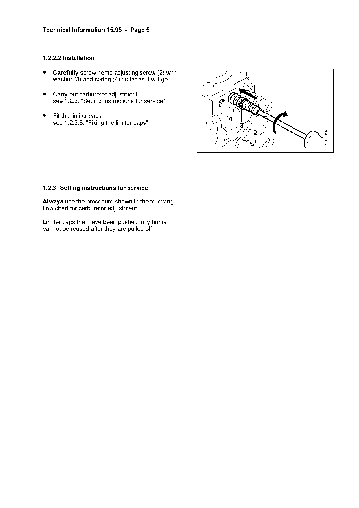
• &DUHIXOO\ screw home adjusting screw (2) with
   washer (3) and spring (4) as far as it will go.

• Carry out carburetor adjustment -
   see 1.2.3: "Setting instructions for service"

• Fit the limiter caps -                                       4
   see 1.2.3.6: "Fixing the limiter caps"                          3

                                                                           354TI006 K
                                                                       2

1.2.3=Setting instructions for service

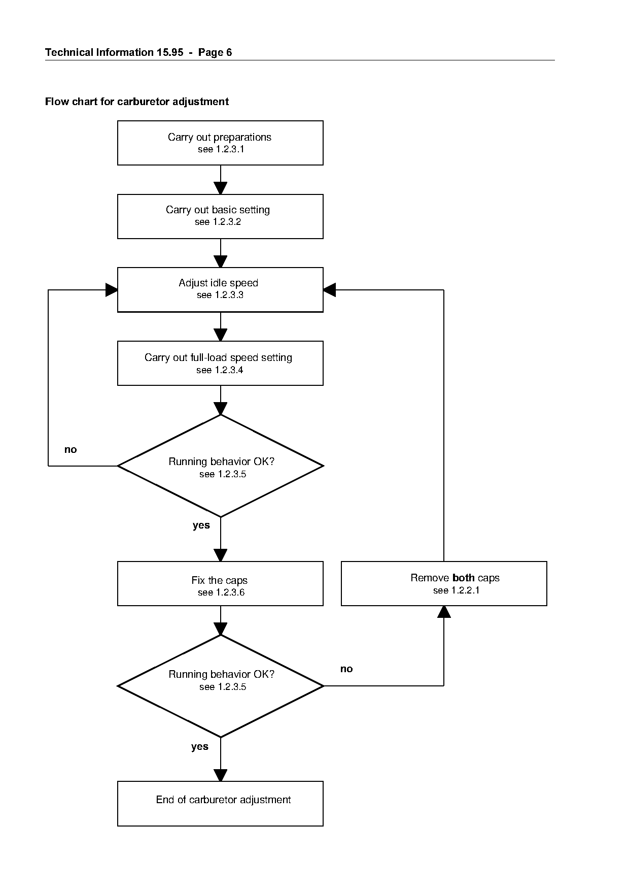
$OZD\V use the procedure shown in the following
flow chart for carburetor adjustment.

Limiter caps that have been pushed fully home
cannot be reused after they are pulled off.
Page 6 of 11
Text of page 6 — search, copy, screen readers
Technical Information 15.95  -  Page 6

Flow chart for carburetor adjustment

                         Carry out preparations
                               see 1.2.3.1

                        Carry out basic setting
                               see 1.2.3.2

                           Adjust idle speed
                               see 1.2.3.3

                    Carry out full-load speed setting
                               see 1.2.3.4

   QR
                         Running behavior OK?
                                see 1.2.3.5

                              \HV

                                                                  Remove ERWK caps

                              Fix the caps
                               see 1.2.3.6                            see 1.2.2.1

                                                         QR
                         Running behavior OK?
                                see 1.2.3.5

                              \HV

                      End of carburetor adjustment
Page 7 of 11
Text of page 7 — search, copy, screen readers
Technical Information 15.95  -  Page 7

1.2.3.1 Preparations

Engine speeds must be checked with a
tachometer.

• Check the air filter and clean if necessary.
• Inspect the spark arresting screen and clean
    or replace if necessary.
• Mount STIHL Autocut or Polymatic head -
    adjust length of lines so that they extend as far
    as line limiting blade on the deflector.

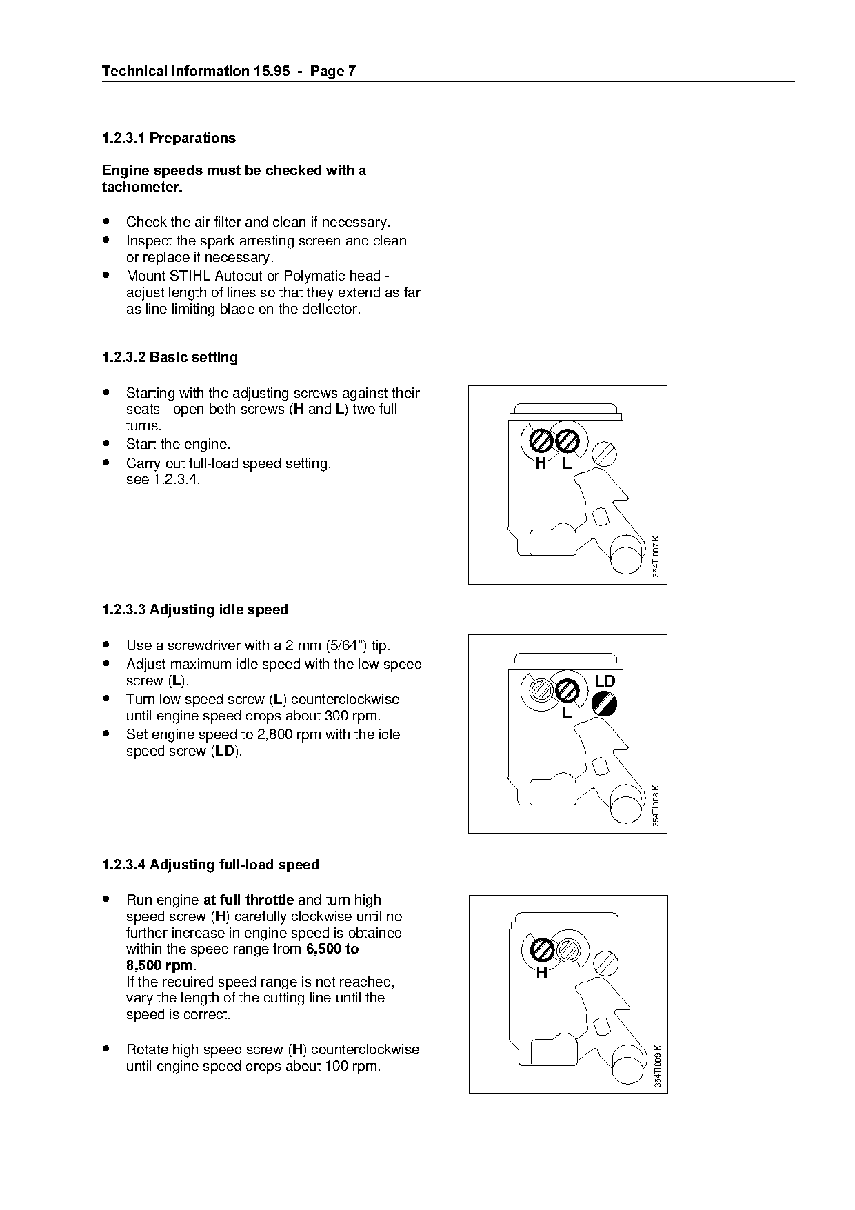
1.2.3.2 Basic setting

• Starting with the adjusting screws against their
    seats - open both screws (+ and /) two full

    turns.
•   Start the engine.

•   Carry out full-load speed setting,                        H L
    see 1.2.3.4.

                                                                           354TI007 K

1.2.3.3 Adjusting idle speed

• Use a screwdriver with a 2 mm (5/64") tip.

• Adjust maximum idle speed with the low speed
    screw (/).

                                                                      LD
• Turn low speed screw (/) counterclockwise
    until engine speed drops about 300 rpm.                       L
• Set engine speed to 2,800 rpm with the idle

    speed screw (/').

                                                                           354TI008 K

1.2.3.4 Adjusting full-load speed

• Run engine at full throttle=~nd turn high
    speed screw (+) carefully clockwise until no
    further increase in engine speed is obtained
====within=the=speed=r~nge=from=6,500 to
    8,500 rpm.
    If the required speed range is not reached,
                                                              H
    vary the length of the cutting line until the
    speed is correct.

• Rotate high speed screw (+) counterclockwise
                                                                             354TI009 K

    until engine speed drops about 100 rpm.
Page 8 of 11
Text of page 8 — search, copy, screen readers
Technical Information 15.95  -  Page 8

1.2.3.5 Checking running behavior

• Open throttle several times and check that
      engine accelerates smoothly - the engine
      must also run smoothly at idle speed.

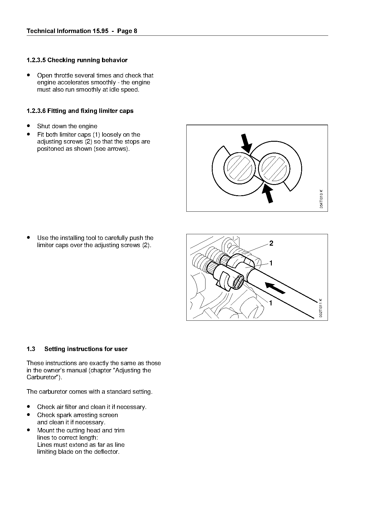
1.2.3.6 Fitting and fixing limiter caps

• Shut down the engine
• Fit both limiter caps (1) loosely on the
      adjusting screws (2) so that the stops are

      positoned as shown (see arrows).

                                                                        354TI010 K
• Use the installing tool to carefully push the
      limiter caps over the adjusting screws (2).                  2


                                                                       002TI011 K
                                                                   1

1.3=====Setting instructions for user

These instructions are exactly the same as those

in the owner’s manual (chapter "Adjusting the
Carburetor").

The carburetor comes with a standard setting.

• Check air filter and clean it if necessary.
• Check spark arresting screen
      and clean it if necessary.
• Mount the cutting head and trim
      lines to correct length:
      Lines must extend as far as line
      limiting blade on the deflector.
Page 9 of 11
Text of page 9 — search, copy, screen readers
Technical Information 15.95  -  Page

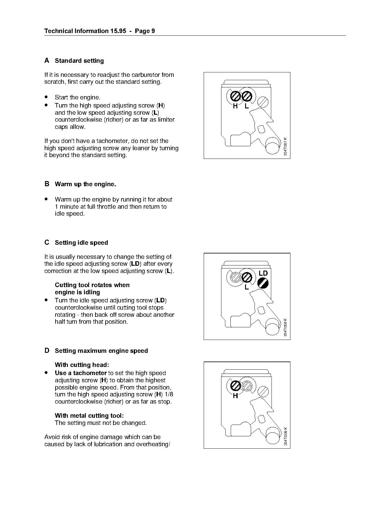
A= =Standard setting

If it is necessary to readjust the carburetor from
scratch, first carry out the standard setting.

• Start the engine.
• Turn the high speed adjusting screw (+)                      H L
    and the low speed adjusting screw (/)
    counterclockwise (richer) or as far as limiter
    caps allow.

                                                                            354TI007 K
If you don‘t have a tachometer, do not set the

high speed adjusting screw any leaner by turning

it beyond the standard setting.

B =Warm up the engine.

• Warm up the engine by running it for about

    1 minute at full throttle and then return to
    idle speed.
C =Setting idle speed

It is usually necessary to change the setting of

the idle speed adjusting screw (/') after every
correction at the low speed adjusting screw (/).                       LD
    Cutting tool rotates when

====engine is idling

•   Turn the idle speed adjusting screw (/')
    counterclockwise until cutting tool stops
    rotating - then back off screw about another
                                                                            354TI008 K

    half turn from that position.

D =Setting maximum engine speed

====With cutting head

• Use a tachometer=to set the high speed
    adjusting screw (+) to obtain the highest
    possible engine speed. From that position,

    turn the high speed adjusting screw (+) 1/8                H
    counterclockwise (richer) or as far as stop.

====With metal cutting tool
    The setting must not be changed.
                                                                             354TI009 K

Avoid risk of engine damage which can be
caused by lack of lubrication and overheating!
Page 10 of 11
Text of page 10 — search, copy, screen readers
Technical Information 15.95  -  Page 10

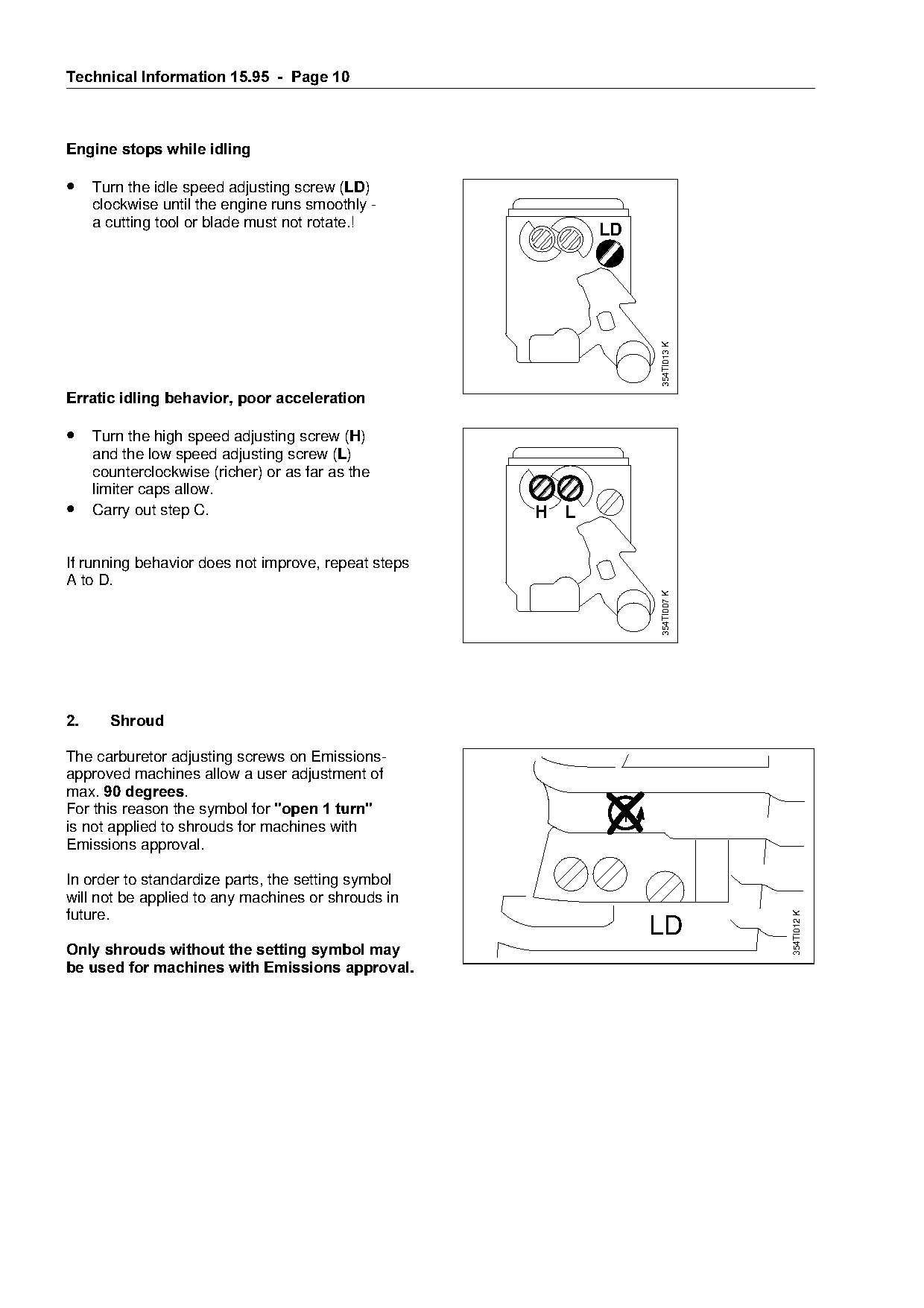
Engine stops while idling

• Turn the idle speed adjusting screw (/')
     clockwise until the engine runs smoothly -
     a cutting tool or blade must not rotate.!
                                                                LD

                                                                     354TI013 K

Erratic idling behavior, poor acceleration

• Turn the high speed adjusting screw (+)

     and the low speed adjusting screw (/)
     counterclockwise (richer) or as far as the
     limiter caps allow.

•    Carry out step C.                                    H L

If running behavior does not improve, repeat steps
A to D.

                                                                     354TI007 K

2.=====Shroud

The carburetor adjusting screws on Emissions-
approved machines allow a user adjustment of
maxK=90 degrees.

For this reason the symbol for "open 1 turn"
is not applied to shrouds for machines with                     H    L
Emissions approval.

In order to standardize parts, the setting symbol
will not be applied to any machines or shrouds in

future.
                                                                                  354TI012 K

                                                                     LD
Only shrouds without the setting symbol may

be used for machines with Emissions approval.
Page 11 of 11
Text of page 11 — search, copy, screen readers
Technical Information 15.95  -  Page 11

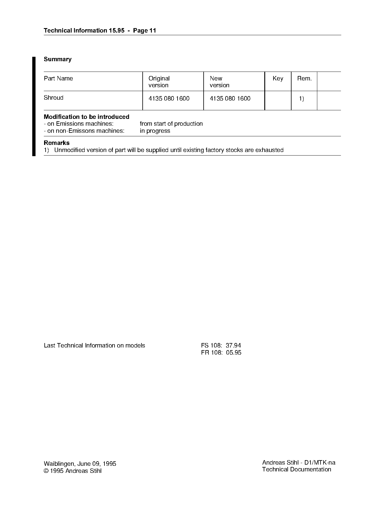
6XPPDU\

Part Name                              Original                New                   Key     Rem.
                                       version                 version
Shroud                                 4135 080 1600           4135 080 1600                 1)

Modification to be introduced
- on Emissions machines:            from start of production
- on non-Emissons machines:         in progress

5HPDUNV

1) Unmodified version of part will be supplied until existing factory stocks are exhausted

Last Technical Information on models                       FS 108: 37.94
                                                           FR 108: 05.95

Waiblingen, June 09, 1995                                                        Andreas Stihl - D1/MTK-na
© 1995 Andreas Stihl                                                             Technical Documentation
Most of these PDFs embed fonts with a shifted character map, so the text above was recovered rather than copied — read it as a faithful but imperfect transcription, and treat the page image above each block as the authority where the two disagree — the figures exist only there, because they are vector drawings that text extraction cannot keep.