Technical Information · issue 23 of 1995
New chainsaw
IssueTI 23/1995
Engine family 1130
Full text
Page 1 of 11
Text of page 1 — search, copy, screen readers
Technical Information

                                                                                                 23.95

New STIHL 017 Chain Saw  -  Series 1130

1.===General description

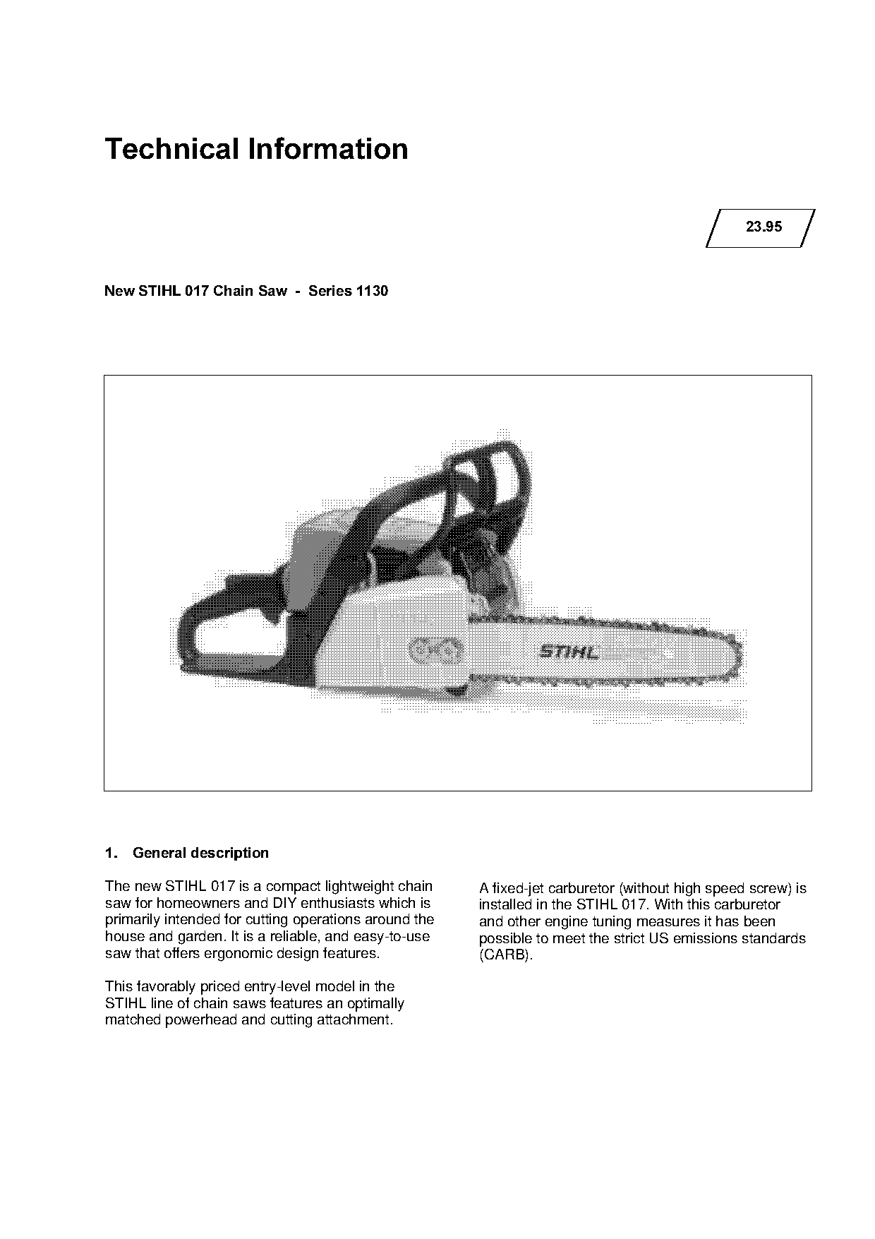
The new STIHL 017 is a compact lightweight chain       A fixed-jet carburetor (without high speed screw) is
saw for homeowners and DIY enthusiasts which is        installed in the STIHL 017. With this carburetor

primarily intended for cutting operations around the   and other engine tuning measures it has been
house and garden. It is a reliable, and easy-to-use    possible to meet the strict US emissions standards
saw that offers ergonomic design features.             (CARB).

This favorably priced entry-level model in the
STIHL line of chain saws features an optimally
matched powerhead and cutting attachment.
Page 2 of 11
Text of page 2 — search, copy, screen readers
Technical Information 23.95  -  Page 2

2.====Equipment

The STIHL 017 is equipped with an AV handle
system, electronic magneto ignition system, inertia-
tripped chain brake and a spark arresting screen in
the exhaust muffler.

3.====Technical description

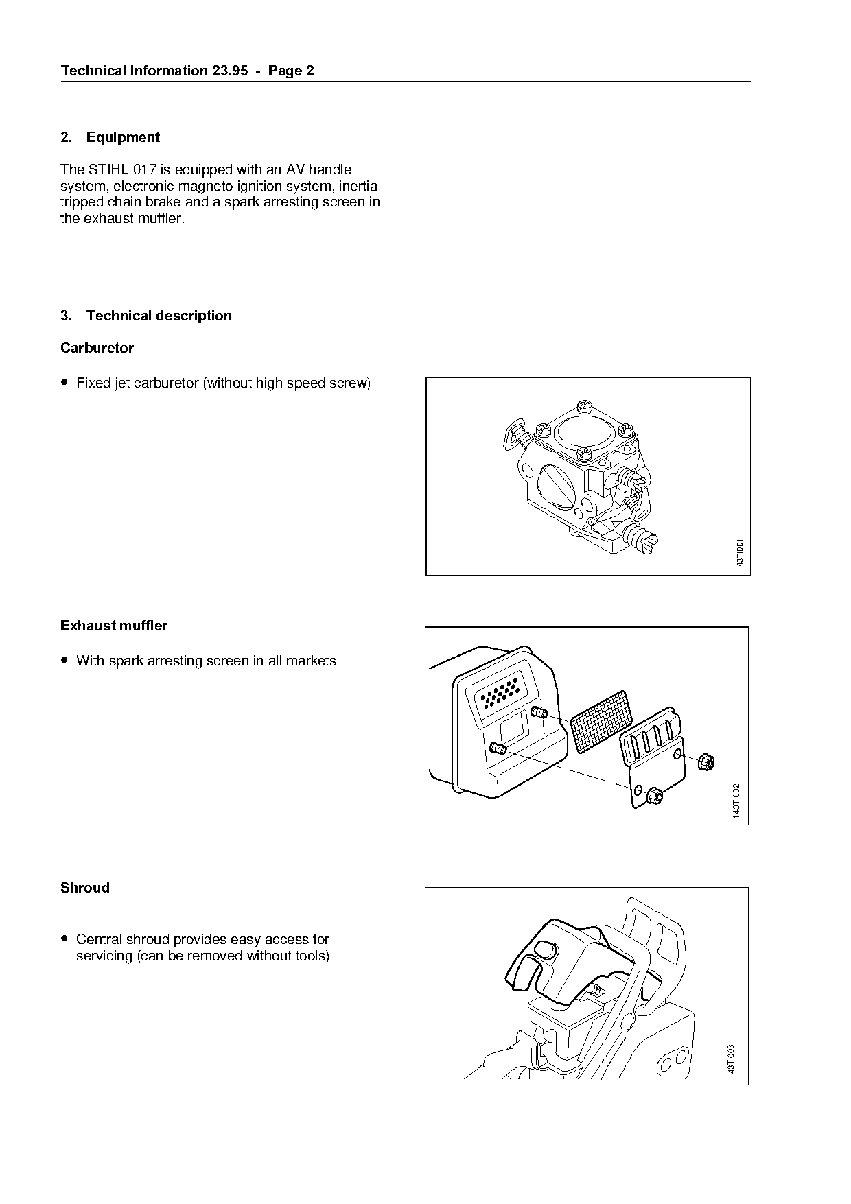
&DUEXUHWRU

• Fixed jet carburetor (without high speed screw)

                                                                                    143TI001

Exhaust muffler

• With spark arresting screen in all markets

                                                                              143TI002

6KURXG

• Central shroud provides easy access for
     servicing (can be removed without tools)
                                                                         143TI003
Page 3 of 11
Text of page 3 — search, copy, screen readers
Technical Information 23.95  -  Page 3

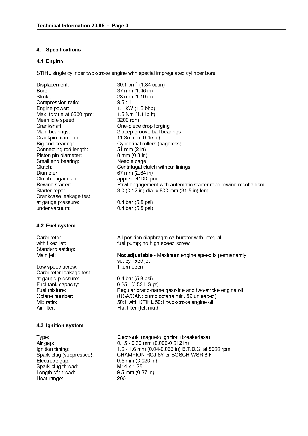
4.===Specifications

4.1=Engine

STIHL single cylinder two-stroke engine with special impregnated cylinder bore

Displacement:                      30.1 cm3 (1.84 cu.in)
Bore:                              37 mm (1.46 in)
Stroke:                            28 mm (1.10 in)
Compression ratio:                 9.5 : 1
Engine power:                      1.1 kW (1.5 bhp)
Max. torque at 6500 rpm:           1.5 Nm (1.1 lb.ft)
Mean idle speed:                   3200 rpm

Crankshaft:                        One-piece drop forging

Main bearings:                     2 deep-groove ball bearings
Crankpin diameter:                 11.35 mm (0.45 in)
Big end bearing:                   Cylindrical rollers (cageless)

Connecting rod length:             51 mm (2 in)
Piston pin diameter:               8 mm (0.3 in)
Small end bearing:                 Needle cage

Clutch:                            Centrifugal clutch without linings
Diameter:                          67 mm (2.64 in)
Clutch engages at:                 approx. 4100 rpm
Rewind starter:
Starter rope:
                                   Pawl engagement with automatic starter rope rewind mechanism
                                   3.0 (0.12 in) dia. x 800 mm (31.5 in) long
Crankcase leakage test
at gauge pressure:                 0.4 bar (5.8 psi)
under vacuum:                      0.4 bar (5.8 psi)

4.2=Fuel system

Carburetor                         All position diaphragm carburetor with integral
with fixed jet:                    fuel pump; no high speed screw

Standard setting:
j~in=jetW==========================Not adjustable=J=j~ximum=engine=speed=is=perm~nently
                                   set by fixed jet
Low speed screw:                   1 turn open

Carburetor leakage test
at gauge pressure:                 0.4 bar (5.8 psi)

Fuel tank capacity:                0.25 l (0.53 US pt)
Fuel mixture:                      Regular brand-name gasoline and two-stroke engine oil
Octane number:                     (USA/CAN: pump octane min. 89 unleaded)
Mix ratio:                         50:1 with STIHL 50:1 two-stroke engine oil

Air filter:                        Flat filter (felt mat)

4.3=Ignition system

Type:                              Electronic magneto ignition (breakerless)
Air gap:                           0.15 - 0.30 mm (0.006-0.012 in)
Ignition timing:                   1.0 - 1.6 mm (0.04-0.063 in) B.T.D.C. at 8000 rpm
Spark plug (suppressed):           CHAMPION RCJ 6Y or BOSCH WSR 6 F
Electrode gap:                     0.5 mm (0.020 in)
Spark plug thread:                 M14 x 1.25
Length of thread:                  9.5 mm (0.37 in)
Heat range:                        200
Page 4 of 11
Text of page 4 — search, copy, screen readers
Technical Information 23.95  -  Page 4

4.4=Cutting attachment

The new Picco Mini=cutting attachment has been
specially designed for small chain saws with
engines up to 1.2 kW (1.6 bhp). Compared to the
well-known Picco Micro, it offers:

• Higher cutting capacity
• 30% less weight
• Reduced cutting noise
• Less sensitive to variations in feed pressure.
  This is a particular advantage for inexperienced

  users

• Enhanced safety provided by 7-tooth nose
  sprocket and offset depth gauges

The Picco mini and Picco Micro bar and chain may
be used with the optional quick chain tensioning
system 1123 007 1008. Picco Mini cutting attach-

ments=must not=be=used=on=m~chines=with=~n
engine power of more than 1.2 kW=ENKS=bhp)!

4.4.1===3/8" Picco Micro Mini Oilomatic chain
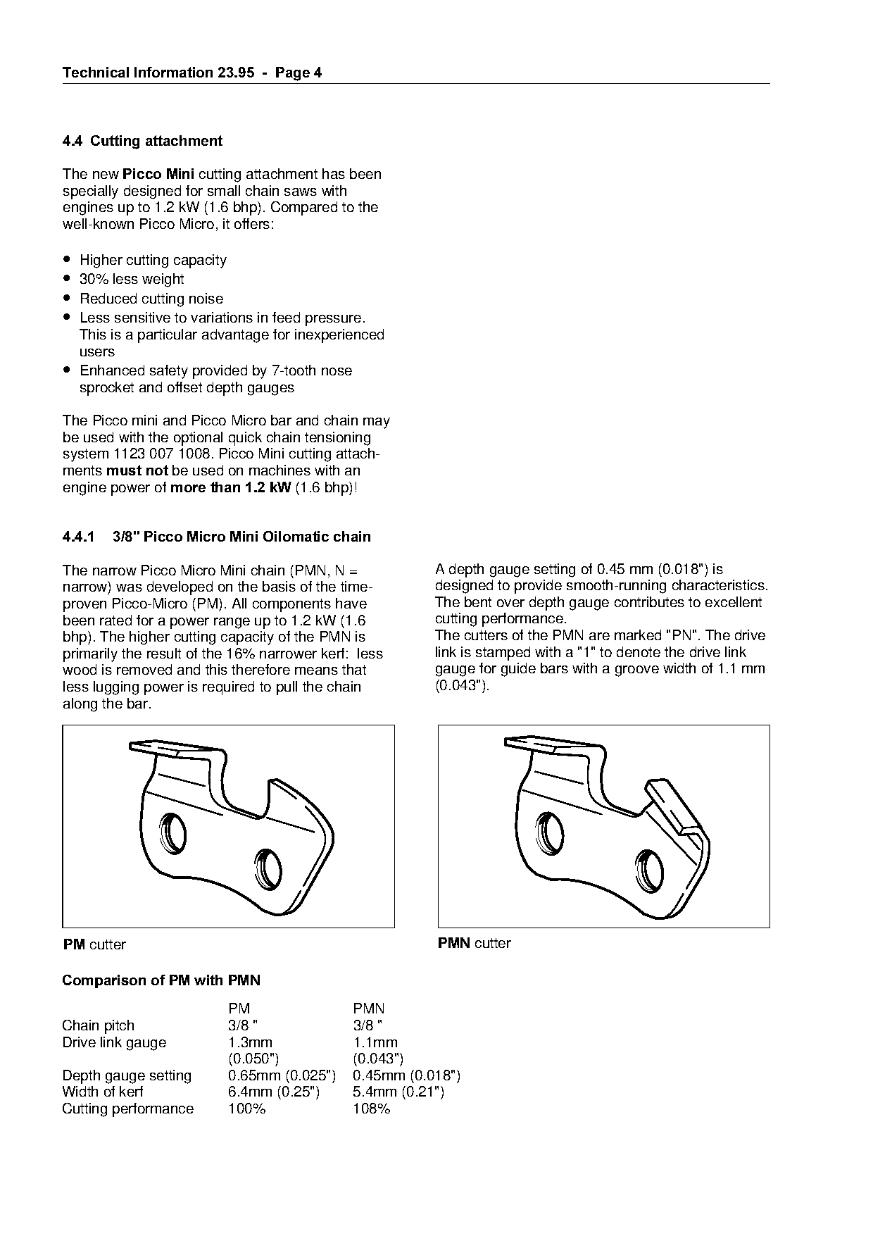
The narrow Picco Micro Mini chain (PMN, N =               A depth gauge setting of 0.45 mm (0.018") is
narrow) was developed on the basis of the time-           designed to provide smooth-running characteristics.
proven Picco-Micro (PM). All components have              The bent over depth gauge contributes to excellent

been rated for a power range up to 1.2 kW (1.6            cutting performance.
bhp). The higher cutting capacity of the PMN is           The cutters of the PMN are marked "PN". The drive
primarily the result of the 16% narrower kerf: less       link is stamped with a "1" to denote the drive link
                                                          gauge for guide bars with a groove width of 1.1 mm

wood is removed and this therefore means that
less lugging power is required to pull the chain          (0.043").

along the bar.

30 cutter                                                 301 cutter

Comparison of PM with PMN
                          PM                  PMN
Chain pitch               3/8 "               3/8 "
Drive link gauge          1.3mm               1.1mm
                          (0.050")            (0.043")
Depth gauge setting       0.65mm (0.025")     0.45mm (0.018")
Width of kerf             6.4mm (0.25")       5.4mm (0.21")
Cutting performance       100%                108%
Page 5 of 11
Text of page 5 — search, copy, screen readers
Technical Information 23.95  -  Page 5

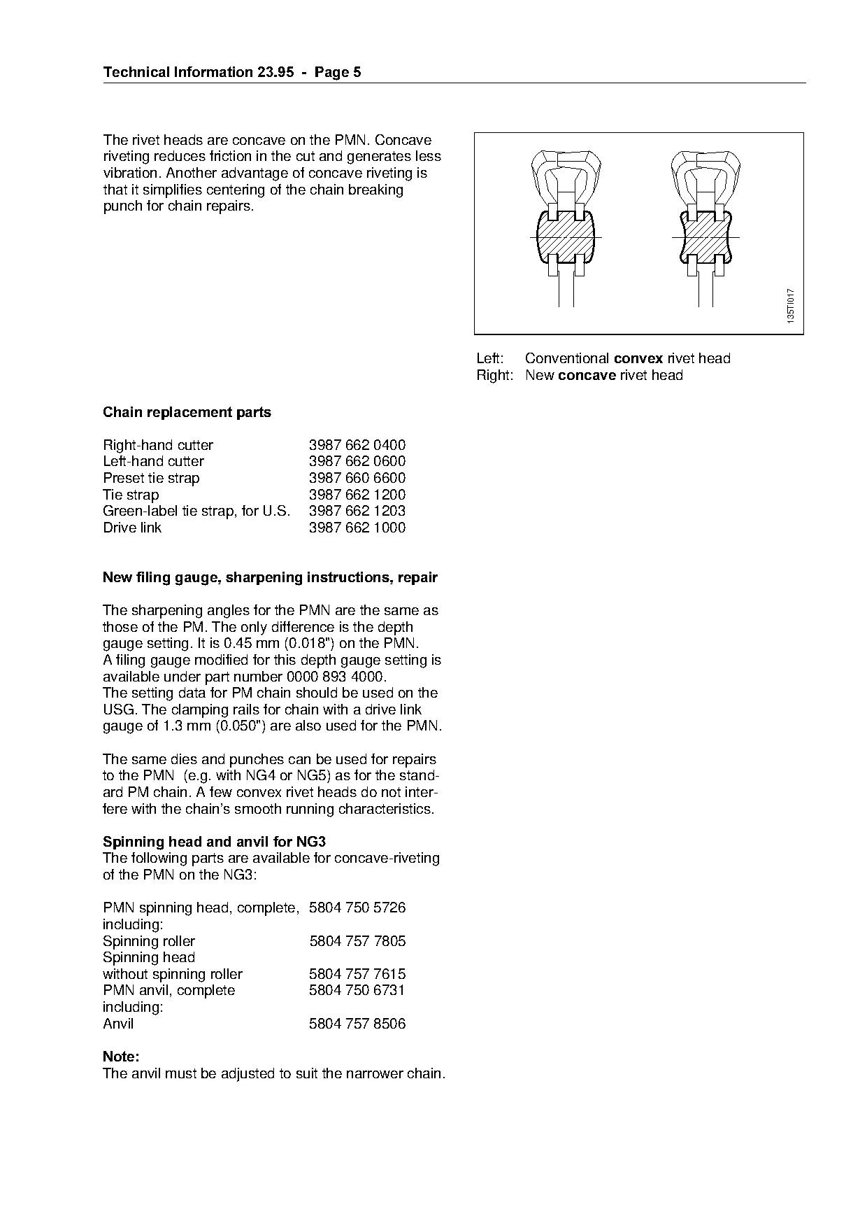
The rivet heads are concave on the PMN. Concave
riveting reduces friction in the cut and generates less
vibration. Another advantage of concave riveting is
that it simplifies centering of the chain breaking
punch for chain repairs.

                                                                                                 135TI017
                                                          Left: Conventional convex=rivet head
                                                          Right: New concave=rivet head

Chain replacement parts

Right-hand cutter                 3987 662 0400
Left-hand cutter                  3987 662 0600

Preset tie strap                  3987 660 6600
Tie strap                         3987 662 1200
Green-label tie strap, for U.S.
Drive link
                                  3987 662 1203
                                  3987 662 1000
New filing gauge, sharpening instructions, repair

The sharpening angles for the PMN are the same as
those of the PM. The only difference is the depth
gauge setting. It is 0.45 mm (0.018") on the PMN.
A filing gauge modified for this depth gauge setting is

available under part number 0000 893 4000.

The setting data for PM chain should be used on the
USG. The clamping rails for chain with a drive link
gauge of 1.3 mm (0.050") are also used for the PMN.

The same dies and punches can be used for repairs
to the PMN (e.g. with NG4 or NG5) as for the stand-
ard PM chain. A few convex rivet heads do not inter-

fere with the chain’s smooth running characteristics.

Spinning head and anvil for NG3

The following parts are available for concave-riveting
of the PMN on the NG3:

PMN spinning head, complete, 5804 750 5726
including:
Spinning roller              5804 757 7805
Spinning head
without spinning roller      5804 757 7615
PMN anvil, complete          5804 750 6731
including:
Anvil                        5804 757 8506

1RWH
The anvil must be adjusted to suit the narrower chain.
Page 6 of 11
Text of page 6 — search, copy, screen readers
Technical Information 23.95  -  Page 6

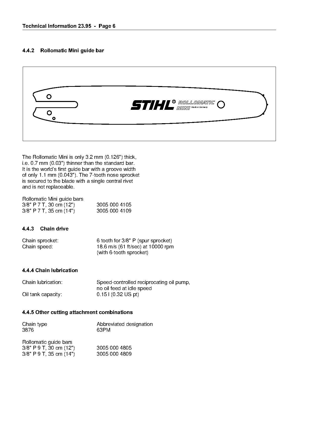
4.4.2===Rollomatic Mini guide bar

                                                                            Made in Germany

The Rollomatic Mini is only 3.2 mm (0.126") thick,
i.e. 0.7 mm (0.03") thinner than the standard bar.

It is the world’s first guide bar with a groove width
of only 1.1 mm (0.043"). The 7-tooth nose sprocket
is secured to the blade with a single central rivet
and is not replaceable.                                               fo
Rollomatic Mini guide bars
3/8" P 7 T, 30 cm (12")          3005 000 4105
3/8" P 7 T, 35 cm (14")          3005 000 4109

4.4.3===Chain drive

Chain sprocket:                  6 tooth for 3/8" P (spur sprocket)
Chain speed:                     18.6 m/s (61 ft/sec) at 10000 rpm

                                 (with 6-tooth sprocket)

4.4.4 Chain lubrication

Chain lubrication:               Speed-controlled reciprocating oil pump,

                                 no oil feed at idle speed
Oil tank capacity:               0.15 l (0.32 US pt)

4.4.5 Other cutting attachment combinations

Chain type                       Abbreviated designation

3876                             63PM

Rollomatic guide bars
3/8" P 9 T, 30 cm (12")          3005 000 4805
3/8" P 9 T, 35 cm (14")          3005 000 4809
Page 7 of 11
Text of page 7 — search, copy, screen readers
Technical Information 23.95  -  Page 7

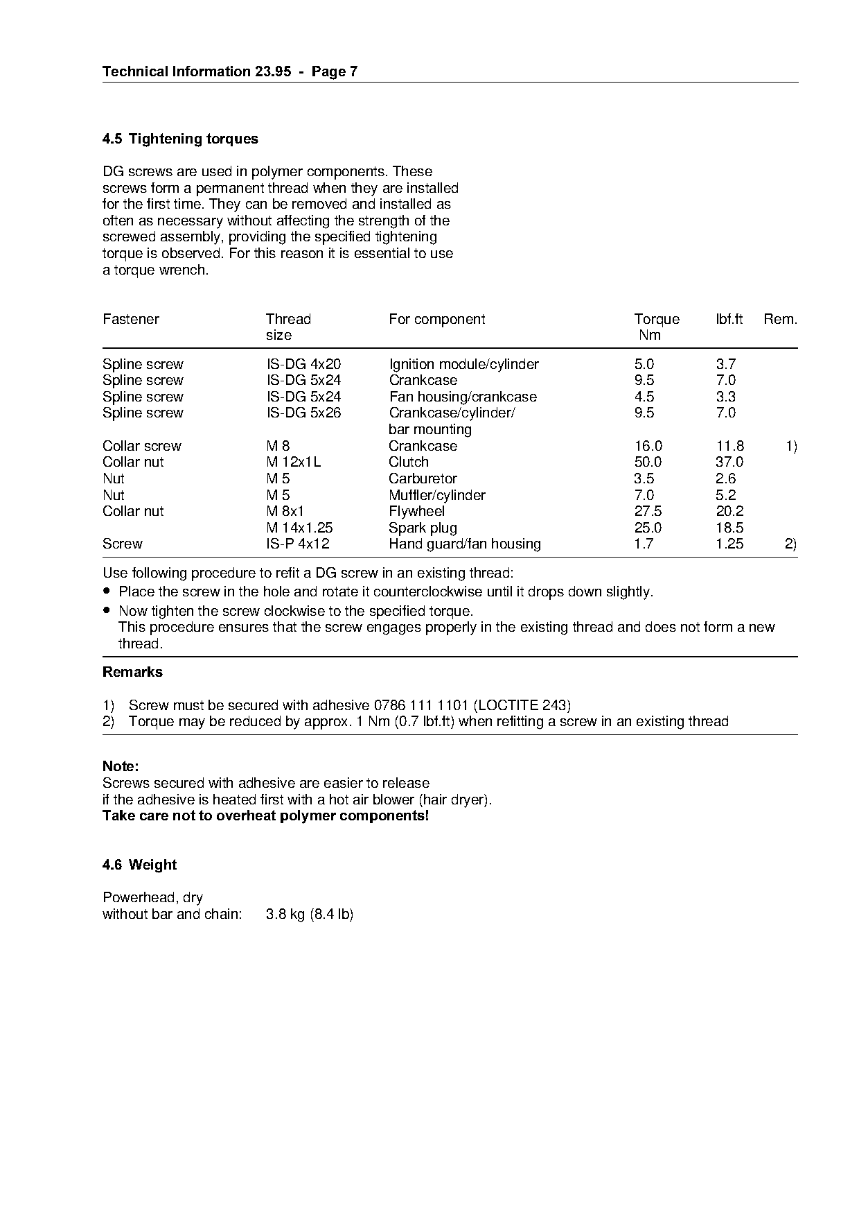
4.5=Tightening torques

DG screws are used in polymer components. These
screws form a permanent thread when they are installed
for the first time. They can be removed and installed as
often as necessary without affecting the strength of the
screwed assembly, providing the specified tightening
torque is observed. For this reason it is essential to use
a torque wrench.

Fastener                    Thread               For component                     Torque      lbf.ft   Rem.
                            size                                                   Nm

Spline screw                IS-DG 4x20           Ignition module/cylinder          5.0         3.7
Spline screw                IS-DG 5x24           Crankcase                         9.5         7.0
Spline screw                IS-DG 5x24           Fan housing/crankcase             4.5         3.3

Spline screw                IS-DG 5x26           Crankcase/cylinder/               9.5         7.0
                                                 bar mounting
Collar screw                M8                   Crankcase                         16.0        11.8       1)

Collar nut                  M 12x1L              Clutch                            50.0        37.0
Nut                         M5                   Carburetor                        3.5         2.6
Nut                         M5                   Muffler/cylinder                  7.0         5.2
Collar nut                  M 8x1
                            M 14x1.25
                                                 Flywheel
                                                 Spark plug
                                                                fo                 27.5
                                                                                   25.0
                                                                                               20.2
                                                                                               18.5
Screw                       IS-P 4x12            Hand guard/fan housing            1.7         1.25       2)
Use following procedure to refit a DG screw in an existing thread:
• Place the screw in the hole and rotate it counterclockwise until it drops down slightly.

• Now tighten the screw clockwise to the specified torque.
  This procedure ensures that the screw engages properly in the existing thread and does not form a new
  thread.

5HPDUNV

1) Screw must be secured with adhesive 0786 111 1101 (LOCTITE 243)
2) Torque may be reduced by approx. 1 Nm (0.7 lbf.ft) when refitting a screw in an existing thread

1RWH
Screws secured with adhesive are easier to release

if the adhesive is heated first with a hot air blower (hair dryer).
Take care not to overheat polymer components!

4.6=Weight

Powerhead, dry
without bar and chain:      3.8 kg (8.4 lb)
Page 8 of 11
Text of page 8 — search, copy, screen readers
Technical Information 23.95  -  Page 8

4.7====Dimensions =without bar and chain

Length:                             380 mm (14.96 in)
Width:                              230 mm (9.0 in)
Height:                             250 mm (9.84 in)

4.8====Standard accessories

Screwdriver                         0000 890 2300 *)
Combination wrench                  1123 893 3400
Chain scabbard                      0000 792 9128

4.9====Special accessories

4.9.1=For user

STIHL repair kit                    1130 900 5000
Filing gauge                        0000 893 4000

Quick chain tensioner               1123 007 1008

4.9.2=For service

Carburetor parts kit                1130 007 1060
*) Not in all markets

5.=====Special tools and servicing aids

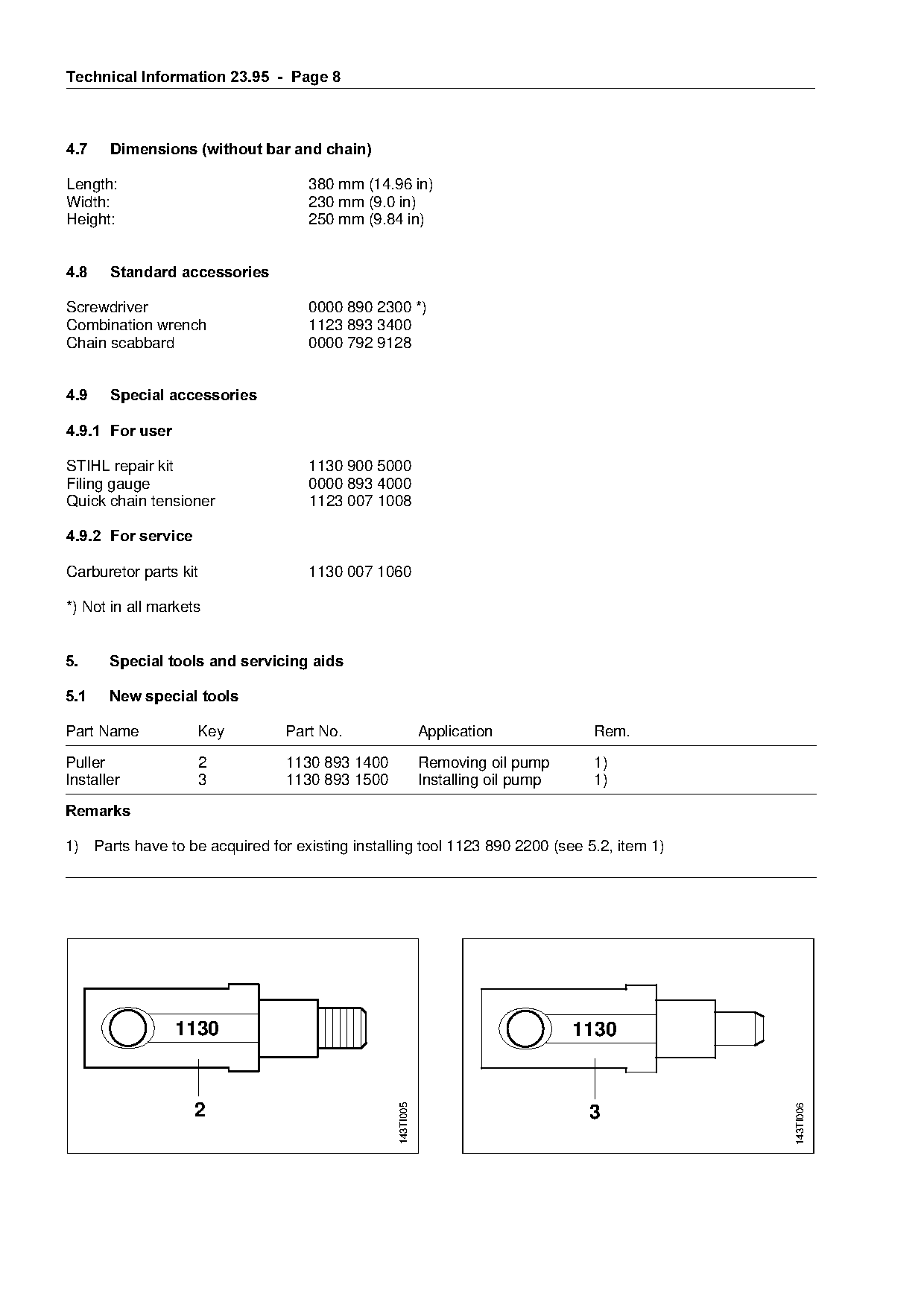
5.1====New special tools

Part Name           Key         Part No.                    Application            Rem.

Puller              2           1130 893 1400               Removing oil pump      1)
Installer           3           1130 893 1500               Installing oil pump    1)

5HPDUNV

1) Parts have to be acquired for existing installing tool 1123 890 2200 (see 5.2, item 1)

                 1130                                                             1130
                                                 143TI005

                    2
                                                                                                143TI006

                                                                                   3
Page 9 of 11
Text of page 9 — search, copy, screen readers
Technical Information 23.95  -  Page

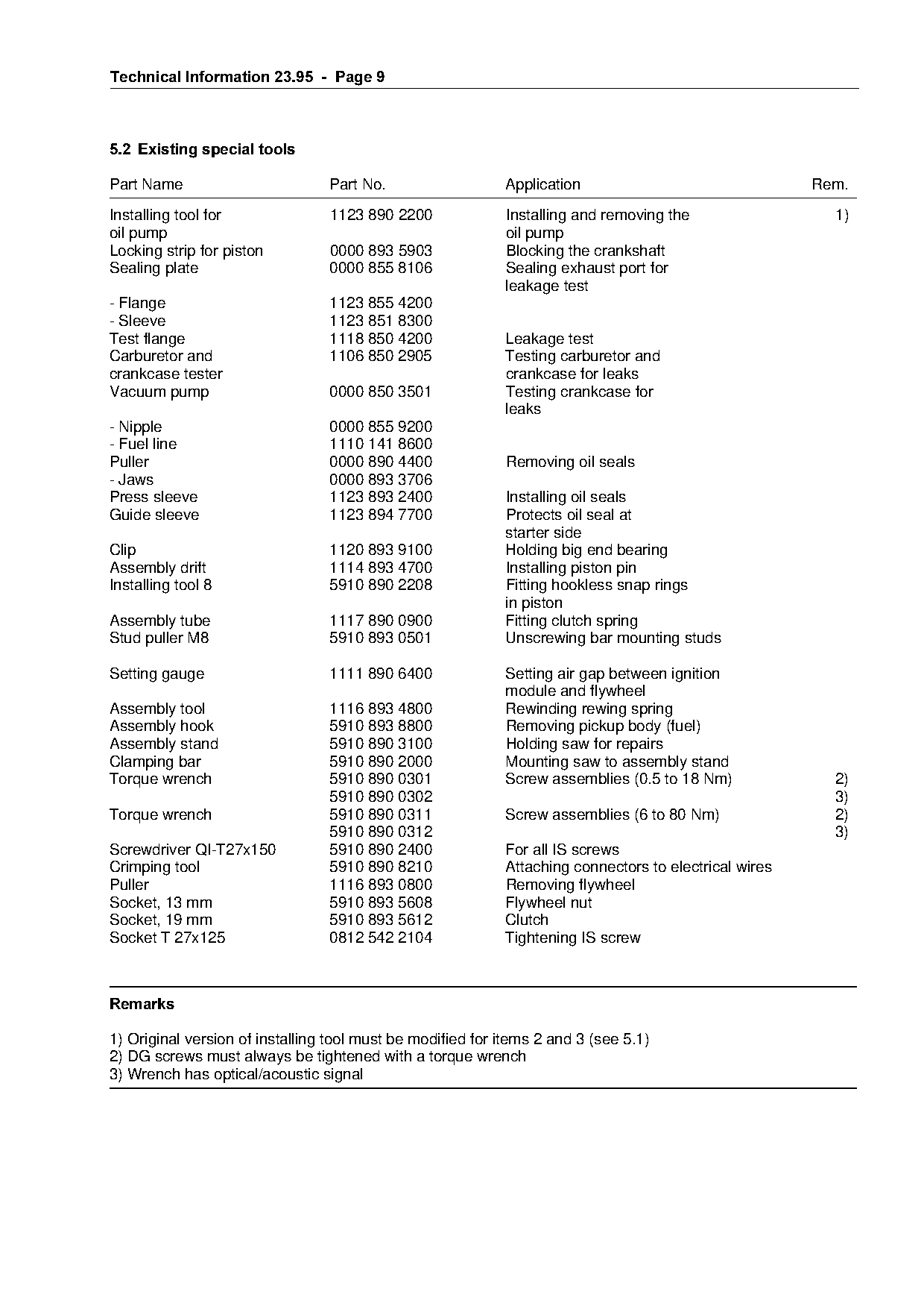
5.2=Existing special tools

Part Name                        Part No.                   Application                                Rem.

Installing tool for              1123 890 2200              Installing and removing the                  1)
oil pump                                                    oil pump
Locking strip for piston         0000 893 5903              Blocking the crankshaft
Sealing plate                    0000 855 8106              Sealing exhaust port for
                                                            leakage test
- Flange                         1123 855 4200
- Sleeve                         1123 851 8300
Test flange                      1118 850 4200              Leakage test
Carburetor and                   1106 850 2905              Testing carburetor and

crankcase tester                                            crankcase for leaks

Vacuum pump                      0000 850 3501              Testing crankcase for
                                                            leaks
- Nipple                         0000 855 9200

- Fuel line                      1110 141 8600
Puller                           0000 890 4400              Removing oil seals
- Jaws                           0000 893 3706

Press sleeve                     1123 893 2400              Installing oil seals
Guide sleeve                     1123 894 7700              Protects oil seal at
                                                            starter side
Clip
Assembly drift
                                 1120 893 9100
                                 1114 893 4700
                                                            Holding big end bearing
                                                            Installing piston pin
Installing tool 8                5910 890 2208              Fitting hookless snap rings
                                                            in piston
Assembly tube                    1117 890 0900              Fitting clutch spring
Stud puller M8                   5910 893 0501              Unscrewing bar mounting studs

Setting gauge                    1111 890 6400              Setting air gap between ignition
                                                            module and flywheel

Assembly tool                    1116 893 4800              Rewinding rewing spring
Assembly hook                    5910 893 8800              Removing pickup body (fuel)

Assembly stand                   5910 890 3100              Holding saw for repairs
Clamping bar                     5910 890 2000              Mounting saw to assembly stand
Torque wrench                    5910 890 0301              Screw assemblies (0.5 to 18 Nm)              2)
                                 5910 890 0302                                                           3)

Torque wrench                    5910 890 0311              Screw assemblies (6 to 80 Nm)                2)
                                 5910 890 0312                                                           3)

Screwdriver QI-T27x150           5910 890 2400              For all IS screws
Crimping tool                    5910 890 8210              Attaching connectors to electrical wires
Puller                           1116 893 0800              Removing flywheel
Socket, 13 mm                    5910 893 5608              Flywheel nut

Socket, 19 mm                    5910 893 5612              Clutch
Socket T 27x125                  0812 542 2104              Tightening IS screw

5HPDUNV

1) Original version of installing tool must be modified for items 2 and 3 (see 5.1)
2) DG screws must always be tightened with a torque wrench
3) Wrench has optical/acoustic signal
Page 10 of 11
Text of page 10 — search, copy, screen readers
Technical Information 23.95  -  Page 10

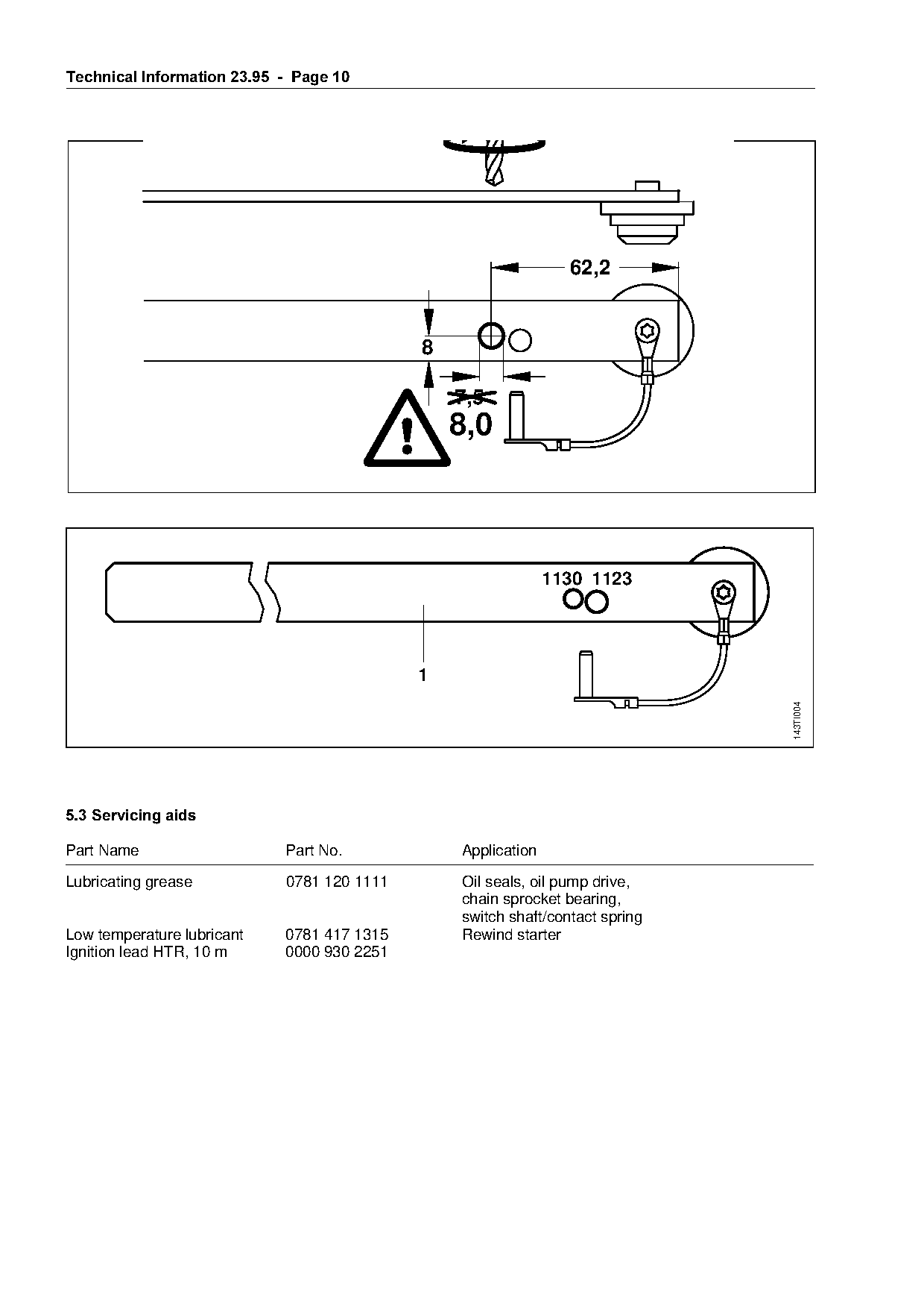
                                                                  62,2


                                                  7,5
                                                  8,0

                                                                1130 1123


                                                                                143TI004

5.3=Servicing aids

Part Name                     Part No.            Application

Lubricating grease            0781 120 1111       Oil seals, oil pump drive,
                                                  chain sprocket bearing,

                                                  switch shaft/contact spring
Low temperature lubricant     0781 417 1315       Rewind starter
Ignition lead HTR, 10 m       0000 930 2251
Page 11 of 11
Text of page 11 — search, copy, screen readers
Technical Information 23.95  -  Page 11

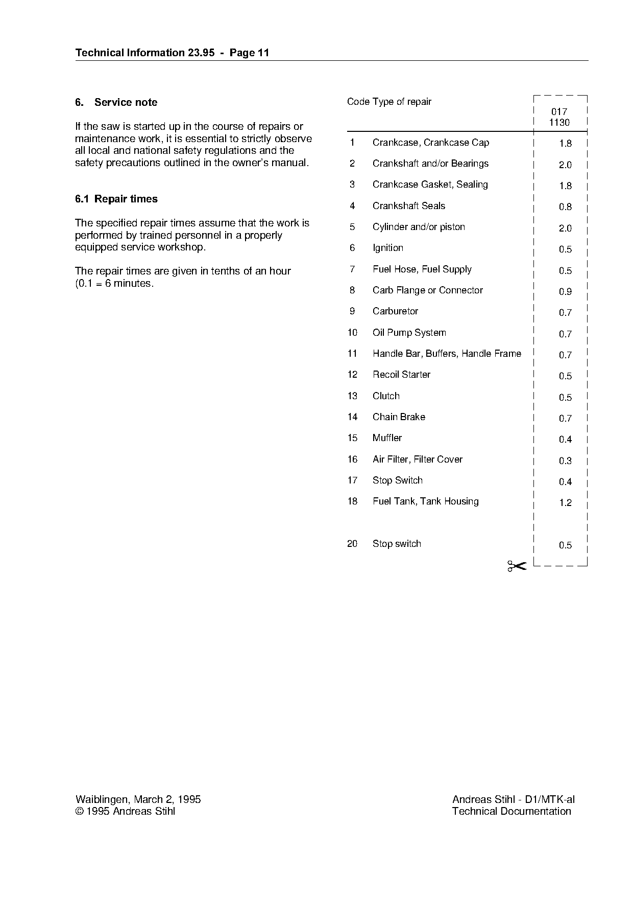
6.===Service note=======================================`ode Type of repair
                                                                                                      017
If the saw is started up in the course of repairs or                                                 1130
maintenance work, it is essential to strictly observe   1    Crankcase, Crankcase Cap                  1.8
all local and national safety regulations and the
safety precautions outlined in the owner’s manual.      2    Crankshaft and/or Bearings                2.0

                                                        3    Crankcase Gasket, Sealing                 1.8
6.1=Repair times
                                                        4    Crankshaft Seals                          0.8
The specified repair times assume that the work is      5    Cylinder and/or piston                    2.0
performed by trained personnel in a properly
equipped service workshop.                              6    Ignition                                  0.5

The repair times are given in tenths of an hour         7    Fuel Hose, Fuel Supply                    0.5
(0.1 = 6 minutes.
                                                        8    Carb Flange or Connector                  0.9

                                                        9    Carburetor                                0.7

                                                        10   Oil Pump System                           0.7

                                                        11   Handle Bar, Buffers, Handle Frame         0.7


                                                        13
                                                             Recoil Starter

                                                             Clutch
                                                                                                       0.5

                                                                                                       0.5
                                                        14   Chain Brake                               0.7

                                                        15   Muffler

                                                                                                       0.4

                                                        16   Air Filter, Filter Cover                  0.3

                                                        17   Stop Switch                               0.4

                                                        18   Fuel Tank, Tank Housing                   1.2

                                                        20   Stop switch                               0.5

                                                                                             ✂

Waiblingen, March 2, 1995                                                         Andreas Stihl - D1/MTK-al
© 1995 Andreas Stihl                                                              Technical Documentation
Most of these PDFs embed fonts with a shifted character map, so the text above was recovered rather than copied — read it as a faithful but imperfect transcription, and treat the page image above each block as the authority where the two disagree — the figures exist only there, because they are vector drawings that text extraction cannot keep.