Technical Information · issue 24 of 1995
Wire bracket on exhaust deflector
Model FS 360, FS 420 clearing saws (versions
IssueTI 24/1995
From serial 31 942 303
Full text
Page 1 of 2
Text of page 1 — search, copy, screen readers
Technical Information

                                                                        24.95

Model FS 360, FS 420 Clearing Saws  -  Series 4116

Wire bracket on exhaust deflector

Model FS 360, FS 420 clearing saws (versions
with spark arresting screen in muffler) from

machine number X 31 942 303=will be supplied
with wire bracket 4116 141 2600.
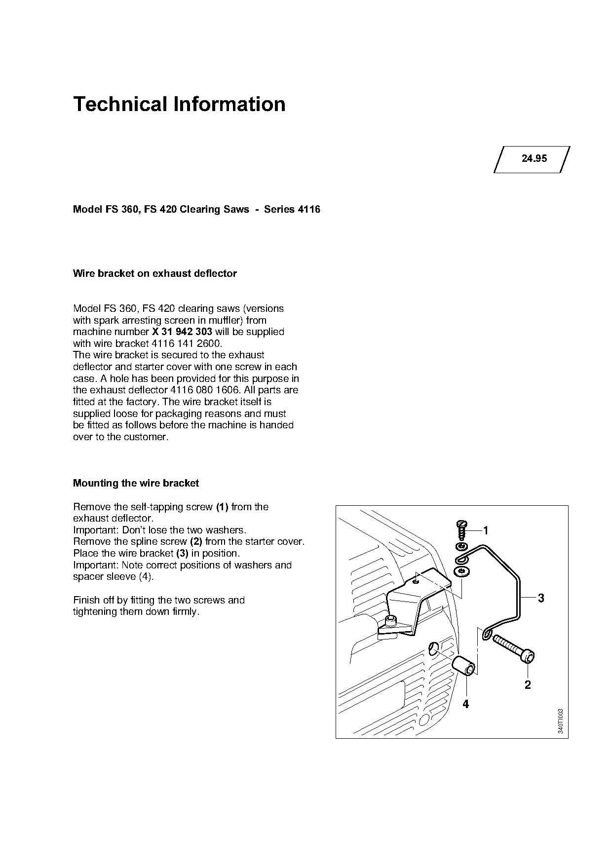
The wire bracket is secured to the exhaust
deflector and starter cover with one screw in each
case. A hole has been provided for this purpose in
the exhaust deflector 4116 080 1606. All parts are
fitted at the factory. The wire bracket itself is
supplied loose for packaging reasons and must

be fitted as follows before the machine is handed
over to the customer.

Mounting the wire bracket

Remove the self-tapping screw 1=from the
exhaust deflector.
Important: Don’t lose the two washers.                              1

Remove the spline screw 2=from the starter cover.
Place the wire bracket 3=in position.

Important: Note correct positions of washers and
spacer sleeve (4).

Finish off by fitting the two screws and                                    3

tightening them down firmly.

                                                                        2
                                                                4
                                                                                340TI003
Page 2 of 2
Text of page 2 — search, copy, screen readers
Technical Information 24.95  -  Page 2

Service note

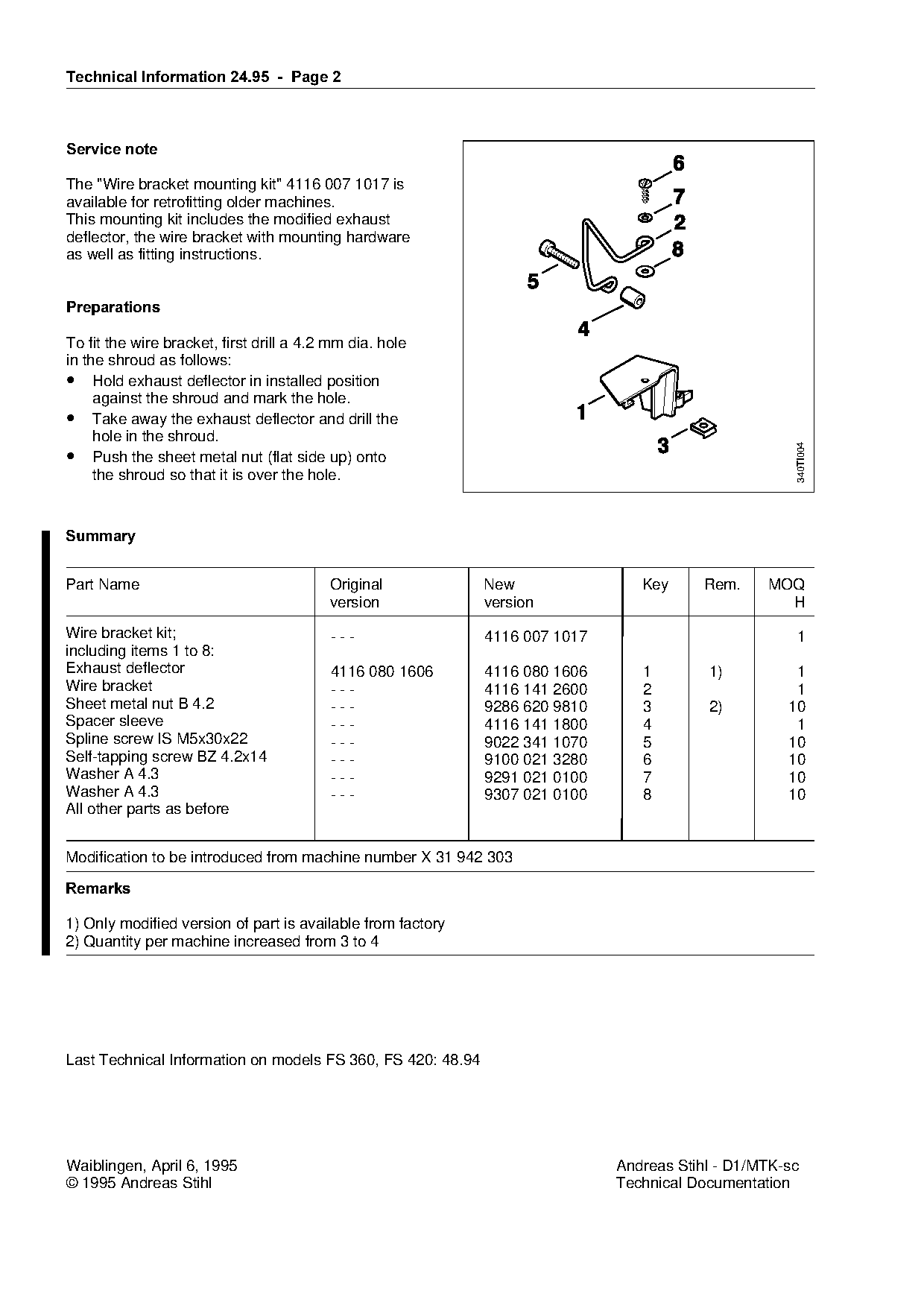
The "Wire bracket mounting kit" 4116 007 1017 is
available for retrofitting older machines.
This mounting kit includes the modified exhaust
deflector, the wire bracket with mounting hardware
as well as fitting instructions.

3UHSDUDWLRQV

To fit the wire bracket, first drill a 4.2 mm dia. hole
in the shroud as follows:

• Hold exhaust deflector in installed position

     against the shroud and mark the hole.
• Take away the exhaust deflector and drill the
     hole in the shroud.

                                                                                                      340TI004
• Push the sheet metal nut (flat side up) onto
     the shroud so that it is over the hole.

6XPPDU\
Part Name                                 Original            New                Key      Rem.    MOQ
                                          version             version                               H
Wire bracket kit;                         ---                 4116 007 1017                           1

including items 1 to 8:
Exhaust deflector                         4116 080 1606       4116 080 1606      1        1)          1
Wire bracket                              ---                 4116 141 2600      2                    1
Sheet metal nut B 4.2                     ---                 9286 620 9810      3        2)         10

Spacer sleeve                             ---                 4116 141 1800      4                    1

Spline screw IS M5x30x22                  ---                 9022 341 1070      5                   10
Self-tapping screw BZ 4.2x14              ---                 9100 021 3280      6                   10
Washer A 4.3                              ---                 9291 021 0100      7                   10
Washer A 4.3                              ---                 9307 021 0100      8                   10

All other parts as before

Modification to be introduced from machine number X 31 942 303

5HPDUNV

1) Only modified version of part is available from factory
2) Quantity per machine increased from 3 to 4

Last Technical Information on models FS 360, FS 420: 48.94

Waiblingen, April 6, 1995                                                     Andreas Stihl - D1/MTK-sc
© 1995 Andreas Stihl                                                          Technical Documentation
Most of these PDFs embed fonts with a shifted character map, so the text above was recovered rather than copied — read it as a faithful but imperfect transcription, and treat the page image above each block as the authority where the two disagree — the figures exist only there, because they are vector drawings that text extraction cannot keep.