Technical Information · issue 28 of 1995
Tank vent/tank housing; filler cap; muffler; shrou
Models 034 and 036 from machine number
Part changes (2)
| Was | Becomes | What the bulletin says |
|---|---|---|
| 1121 182 0900 | 1125 182 0900 | The original version 1121 182 0900 has been be replaced by version 1125 182 0900. |
| 1125 790 1707 | 1125 790 1702 | The original front handle 1125 790 1707 has been replaced by the version 1125 790 1702. |
Full text
Page 1 of 5
Text of page 1 — search, copy, screen readers
Technical Information

                                                                                28.95

Model 034, 036 Chainsaws=-  Series 1125

&RQWHQWV

1. Tank housing (modified shape)
1.1 Tank vent (valve, filter, cap)

1.2 Filler cap
2. Muffler (versions with spark arresting screen)
3. Shroud/rotary shutter

4. Electric handle heating
4.1 Flywheel
4.2 Front handle/heating elements
1.=Tank housing
1.1=Tank vent
                                                                    3

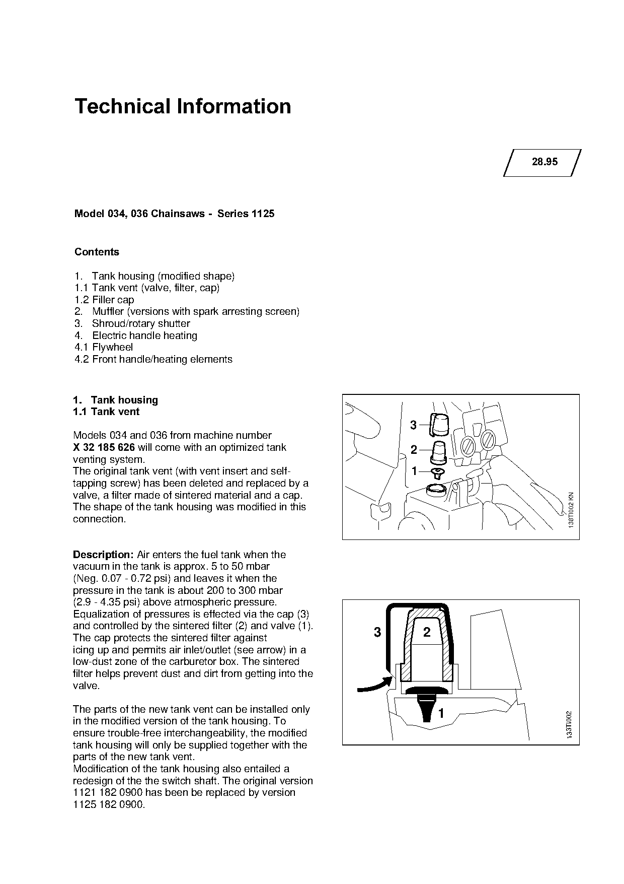
Models 034 and 036 from machine number
X 32 185 626=will come with an optimized tank                       2
venting system.
The original tank vent (with vent insert and self-                  1

tapping screw) has been deleted and replaced by a
valve, a filter made of sintered material and a cap.

                                                                                          138TI002 KN

The shape of the tank housing was modified in this
connection.

Description:=^ir enters the fuel tank when the
vacuum in the tank is approx. 5 to 50 mbar

(Neg. 0.07 - 0.72 psi) and leaves it when the
pressure in the tank is about 200 to 300 mbar
(2.9 - 4.35 psi) above atmospheric pressure.

Equalization of pressures is effected via the cap (3)
and controlled by the sintered filter (2) and valve (1).
The cap protects the sintered filter against                    3       2
icing up and permits air inlet/outlet (see arrow) in a

low-dust zone of the carburetor box. The sintered
filter helps prevent dust and dirt from getting into the
valve.

The parts of the new tank vent can be installed only                        1
                                                                                        133TI002

in the modified version of the tank housing. To
ensure trouble-free interchangeability, the modified
tank housing will only be supplied together with the
parts of the new tank vent.
Modification of the tank housing also entailed a
redesign of the the switch shaft. The original version
1121 182 0900 has been be replaced by version
1125 182 0900.
Page 2 of 5
Text of page 2 — search, copy, screen readers
Technical Information 28.95  -  Page 2

1.2=Filler cap

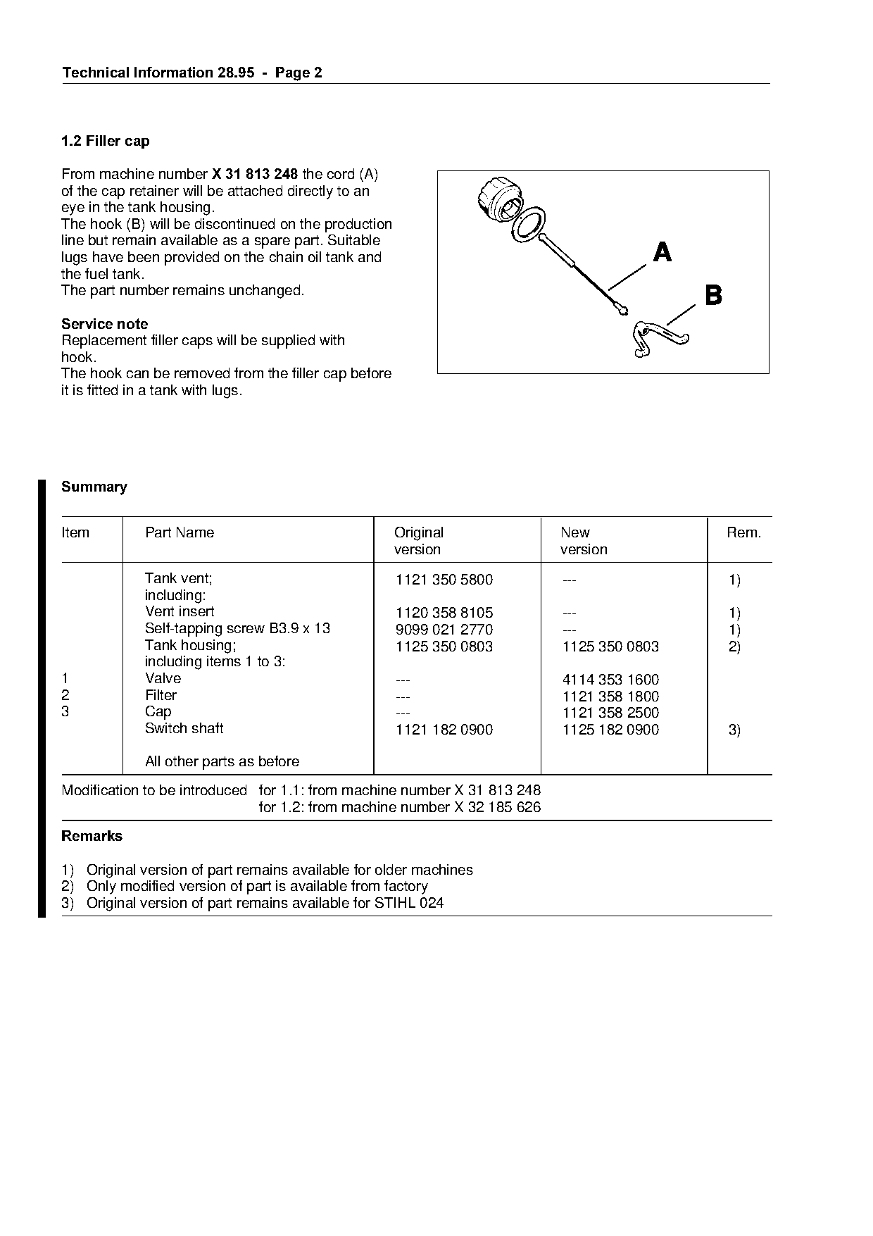
From machine number X 31 813 248=the cord (A)
of the cap retainer will be attached directly to an
eye in the tank housing.
The hook (B) will be discontinued on the production
line but remain available as a spare part. Suitable
lugs have been provided on the chain oil tank and                                     A
the fuel tank.
The part number remains unchanged.
                                                                                          B
Service note
Replacement filler caps will be supplied with

hook.

The hook can be removed from the filler cap before
it is fitted in a tank with lugs.

6XPPDU\

Item         Part Name                                Original
                                                                   fo     New                 Rem.
                                                      version             version
             Tank vent;                               1121 350 5800       ---                 1)
             including:

             Vent insert                              1120 358 8105       ---                 1)
             Self-tapping screw B3.9 x 13             9099 021 2770       ---                 1)
             Tank housing;                            1125 350 0803       1125 350 0803       2)
             including items 1 to 3:

1            Valve                                    ---                 4114 353 1600
2            Filter

                                                      ---                 1121 358 1800
3            Cap                                      ---                 1121 358 2500
             Switch shaft                             1121 182 0900       1125 182 0900       3)

             All other parts as before
Modification to be introduced for 1.1: from machine number X 31 813 248

                              for 1.2: from machine number X 32 185 626
5HPDUNV

1) Original version of part remains available for older machines
2) Only modified version of part is available from factory
3) Original version of part remains available for STIHL 024
Page 3 of 5
Text of page 3 — search, copy, screen readers
Technical Information 28.95  -  Page 3

2.=Muffler =USA only

In order to standardize parts, muffler 1125 140 0608
(16 mm/0.63" dia. exhaust bore) will be replaced by
the version 1125 140 0609 (11 mm/0.43" exhaust
bore).

The muffler kit 1125 140 0651 (USA) offered for the
034 has been deleted. Kit 1125 140 0652 will be
supplied in its place.

6XPPDU\

Item         Part Name                                  Original         New                 Rem.
                                                        version          version

1            Muffler;                                   1125 140 0608    1125 140 0609       1)
             including items 2 to 4:
2            Upper casing                               1125 145 0805    1125 145 0805
3
4
             Screen
             Lower casing                               -*-
                                                        1125 141 9001    1125 141 9001
                                                                         -*-                 2)
             "Wood Boss" muffler kit                    1125 140 0651    1125 140 0652       1)
             including item 1
             All other parts as before

Modification to be introduced: in progress
5HPDUNV

1) Original version of part no longer available from factory

2) Part not available as separate item

3.=Shroud/rotary shutter

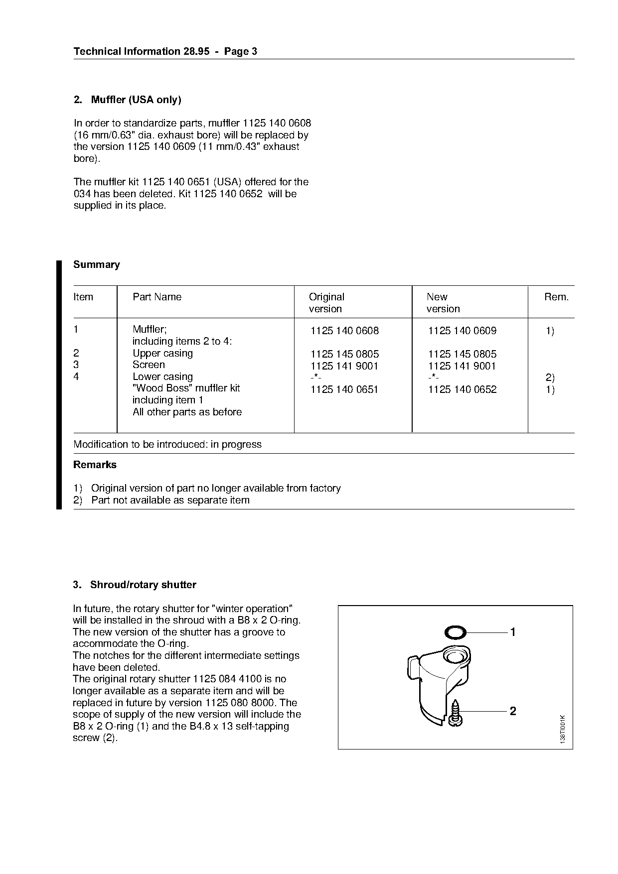
In future, the rotary shutter for "winter operation"
will be installed in the shroud with a B8 x 2 O-ring.
The new version of the shutter has a groove to                                           1

accommodate the O-ring.
The notches for the different intermediate settings
have been deleted.
The original rotary shutter 1125 084 4100 is no
longer available as a separate item and will be
replaced in future by version 1125 080 8000. The
scope of supply of the new version will include the                                      2
                                                                                                  138TI001K

B8 x 2 O-ring (1) and the B4.8 x 13 self-tapping
screw (2).
Page 4 of 5
Text of page 4 — search, copy, screen readers
Technical Information 28.95  -  Page 4

6XPPDU\

Item         Part Name                                  Original                 New                  Rem.
                                                        version                  version
             Rotary shutter                             1125 084 4100             ---                 1)
             Rotary shutter;                            ---                       1125 080 8000
             including items 1 and 2:                   ---                       9646 945 0590
1            O-ring B8 x 2                              ---                       9099 021 3760
2            Self-tapping screw B4.8 x 13

Modification to be introduced: in progress

5HPDUNV

1) Original version of part no longer available from factory

4.=Electric handle heating

4.1=Flywheel
=====only models with heated handles
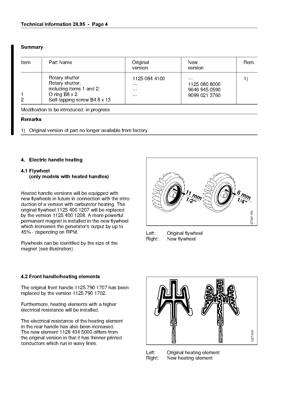
Heated handle versions will be equipped with                                    11                 6m
                                                                                   m                    m
new flywheels in future in connection with the intro-                           1/2 m              1/4
                                                                                   "                   "

duction of a version with carburetor heating. The
original flywheel 1125 400 1207 will be replaced

                                                                                                            32TI001 KN
by the version 1125 400 1208. A more powerful
permanent magnet is installed in the new flywheel

which increases the generator’s output by up to
45% - depending on RPM.

                                                              Left:     Original flywheel
                                                              Right:    New flywheel
Flywheels can be identified by the size of the
magnet (see illustration).

4.2=Front handle/heating elements

The original front handle 1125 790 1707 has been
replaced by the version 1125 790 1702.

Furthermore, heating elements with a higher
electrical resistance will be installed.

The electrical resistance of the heating element
in the rear handle has also been increased.
                                                                                                              132TI003

The new element 1128 434 5000 differs from
the original version in that it has thinner printed
conductors which run in wavy lines.
                                                              Left:     Original heating element
                                                              Right:    New heating element
Page 5 of 5
Text of page 5 — search, copy, screen readers
Technical Information 28.95  -  Page 5

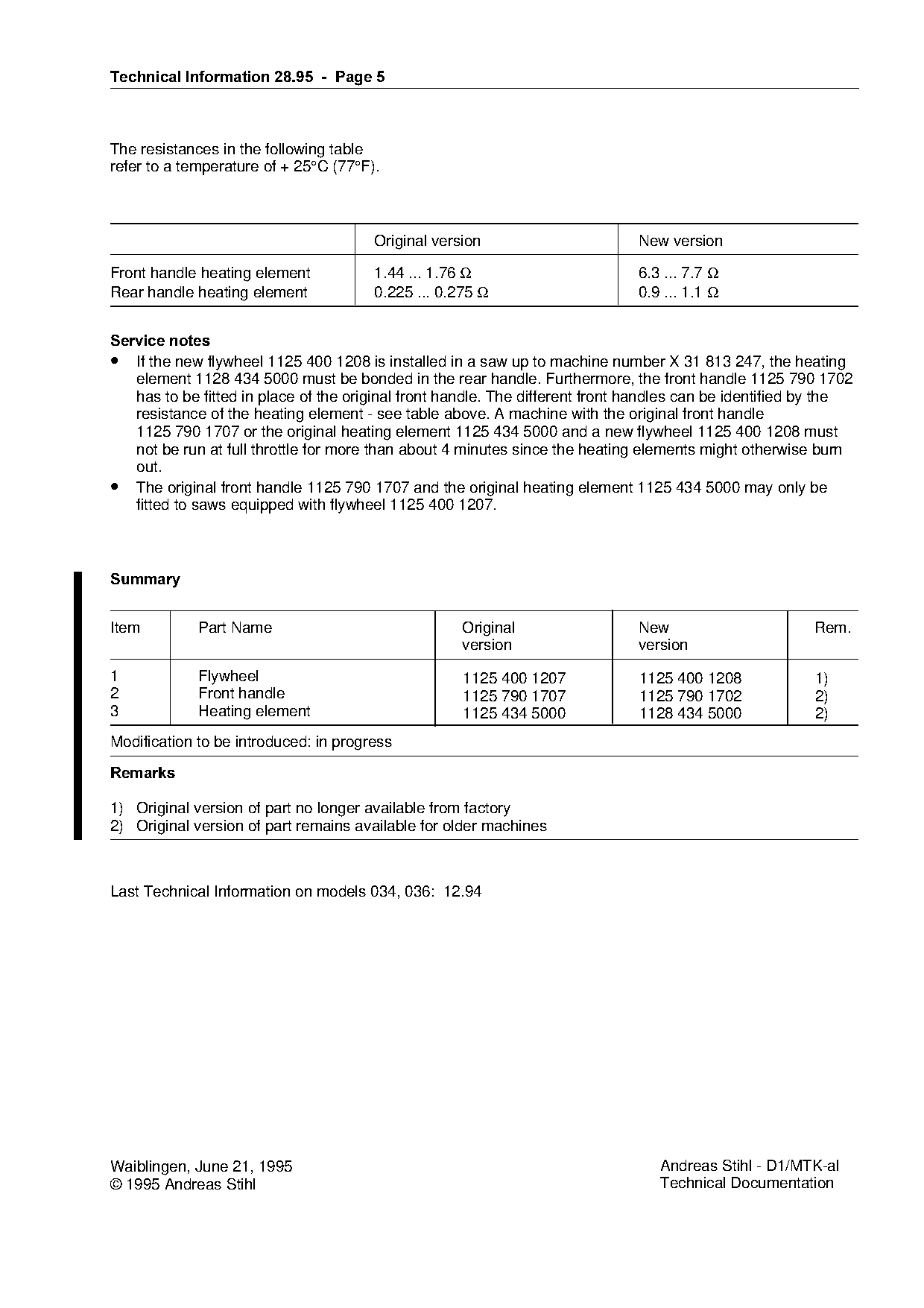
The resistances in the following table
refer to a temperature of + 25°C (77°F).

                                       Original version                       New version

Front handle heating element           1.44 ... 1.76 Ω                        6.3 ... 7.7 Ω
Rear handle heating element            0.225 ... 0.275 Ω                      0.9 ... 1.1 Ω

Service notes
• If the new flywheel 1125 400 1208 is installed in a saw up to machine number X 31 813 247, the heating

   element 1128 434 5000 must be bonded in the rear handle. Furthermore, the front handle 1125 790 1702

   has to be fitted in place of the original front handle. The different front handles can be identified by the
   resistance of the heating element - see table above. A machine with the original front handle
   1125 790 1707 or the original heating element 1125 434 5000 and a new flywheel 1125 400 1208 must

   not be run at full throttle for more than about 4 minutes since the heating elements might otherwise burn
   out.
• The original front handle 1125 790 1707 and the original heating element 1125 434 5000 may only be

   fitted to saws equipped with flywheel 1125 400 1207.

6XPPDU\

Item         Part Name                              Original                  New                        Rem.

                                                    version                   version

1            Flywheel                               1125 400 1207              1125 400 1208             1)
2            Front handle                           1125 790 1707              1125 790 1702             2)

3            Heating element                        1125 434 5000              1128 434 5000             2)

Modification to be introduced: in progress

5HPDUNV

1) Original version of part no longer available from factory
2) Original version of part remains available for older machines

Last Technical Information on models 034, 036: 12.94

Waiblingen, June 21, 1995                                                         Andreas Stihl - D1/MTK-al
© 1995 Andreas Stihl                                                              Technical Documentation
Most of these PDFs embed fonts with a shifted character map, so the text above was recovered rather than copied — read it as a faithful but imperfect transcription, and treat the page image above each block as the authority where the two disagree — the figures exist only there, because they are vector drawings that text extraction cannot keep.