Technical Information · issue 30 of 1995
Air filter system with compensator; decompression
Model 036 chainsaws from machine number
Part changes (4)
| Was | Becomes | What the bulletin says |
|---|---|---|
| 1125 182 0900 | 1125 182 0901 | The original version 1125 182 0900 has been replaced by version 1125 182 0901. |
| 1125 350 0803 | 1125 350 0813 | Tank housing 1125 350 0803 will be replaced by version 1125 350 0813. |
| 1106 405 1000 | 1128 405 1000 | 3.=Spark plug terminal =also for STIHL 034=ppark plug terminal 1106 405 1000 will be replaced by version 1128 405 1000 to help improve the security of the ignition lead. |
| 0000 998 0603 | 0000 998 0604 | Leg spring 0000 998 0603 has been deleted and replaced by version 0000 998 0604. |
Full text
Page 1 of 8
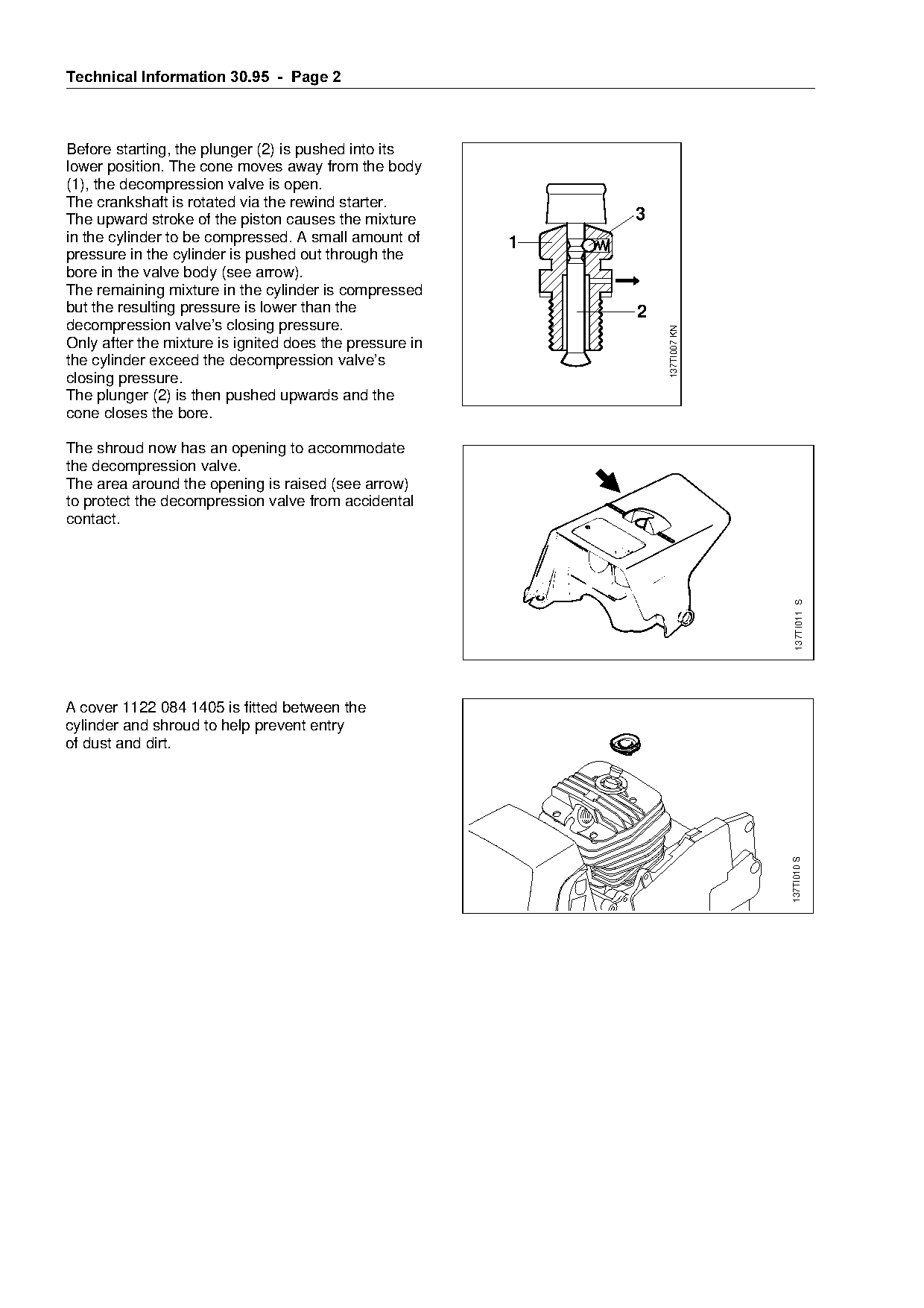
Text of page 1 — search, copy, screen readers
Technical Information

                                                                                             30.95

Model 036 Chainsaws  -  Series 1125

&RQWHQWV

1. New decompression valve (cylinder, shroud),
   air filter system with compensator (air filter, carburetor,
   carburetor box cover)

2. Tank housing (longer collar screws)
3. Spark plug terminal
4. Combination wrench

1.=Decompression valve,
===air filter system with compensator============================fo
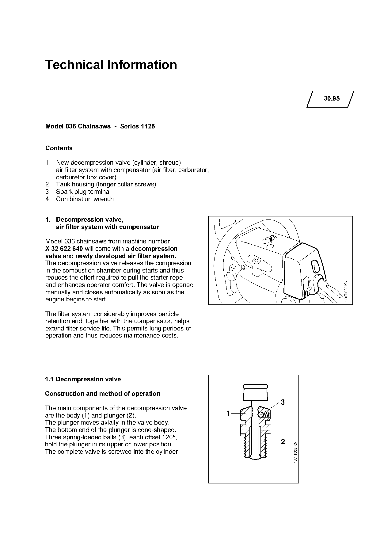
Model 036 chainsaws from machine number
X 32 622 640 will come with ~ decompression
valve ~nd newly developed air filter system.

The decompression valve releases the compression
in the combustion chamber during starts and thus
reduces the effort required to pull the starter rope

                                                                                                     138TI003 KN
and enhances operator comfort. The valve is opened

manually and closes automatically as soon as the
engine begins to start.

The filter system considerably improves particle
retention and, together with the compensator, helps
extend filter service life. This permits long periods of

operation and thus reduces maintenance costs.

1.1=Decompression valve

Construction and method of operation

                                                                           3
The main components of the decompression valve
are the body (1) and plunger (2).                                 1
The plunger moves axially in the valve body.
The bottom end of the plunger is cone-shaped.
Three spring-loaded balls (3), each offset 120°,
                                                                           2
                                                                               137TI006 KN

hold the plunger in its upper or lower position.
The complete valve is screwed into the cylinder.
Page 2 of 8
Text of page 2 — search, copy, screen readers
Technical Information 30.95  -  Page 2

Before starting, the plunger (2) is pushed into its
lower position. The cone moves away from the body
(1), the decompression valve is open.
The crankshaft is rotated via the rewind starter.
The upward stroke of the piston causes the mixture                     3
in the cylinder to be compressed. A small amount of           1
pressure in the cylinder is pushed out through the
bore in the valve body (see arrow).
The remaining mixture in the cylinder is compressed
but the resulting pressure is lower than the                           2
decompression valve’s closing pressure.

                                                                           137TI007 KN
Only after the mixture is ignited does the pressure in
the cylinder exceed the decompression valve’s

closing pressure.

The plunger (2) is then pushed upwards and the
cone closes the bore.

The shroud now has an opening to accommodate
the decompression valve.
The area around the opening is raised (see arrow)

to protect the decompression valve from accidental
contact.

                                                                                           137TI011 S

A cover 1122 084 1405 is fitted between the

cylinder and shroud to help prevent entry

of dust and dirt.

                                                                                         137TI010 S
Page 3 of 8
Text of page 3 — search, copy, screen readers
Technical Information 30.95  -  Page 3

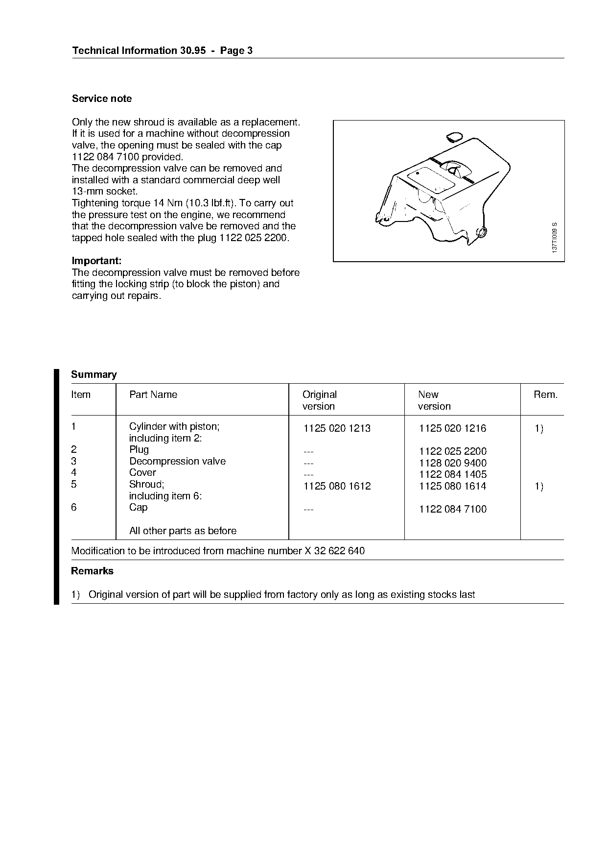
Service note

Only the new shroud is available as a replacement.
If it is used for a machine without decompression
valve, the opening must be sealed with the cap
1122 084 7100 provided.
The decompression valve can be removed and
installed with a standard commercial deep well
13-mm socket.
Tightening torque 14 Nm (10.3 lbf.ft). To carry out
the pressure test on the engine, we recommend
that the decompression valve be removed and the

                                                                                                      137TI009 S
tapped hole sealed with the plug 1122 025 2200.

,PSRUWDQW
The decompression valve must be removed before
fitting the locking strip (to block the piston) and

carrying out repairs.

6XPPDU\
Item         Part Name                                Original                  New              Rem.
                                                      version                   version

1            Cylinder with piston;                    1125 020 1213             1125 020 1216    1)
             including item 2:
2            Plug                                     ---                       1122 025 2200
3            Decompression valve                      ---                       1128 020 9400

4            Cover                                    ---                       1122 084 1405

5            Shroud;                                  1125 080 1612             1125 080 1614    1)
             including item 6:
6            Cap                                      ---                       1122 084 7100

             All other parts as before
Modification to be introduced from machine number X 32 622 640

5HPDUNV

1) Original version of part will be supplied from factory only as long as existing stocks last
Page 4 of 8
Text of page 4 — search, copy, screen readers
Technical Information 30.95  -  Page 4

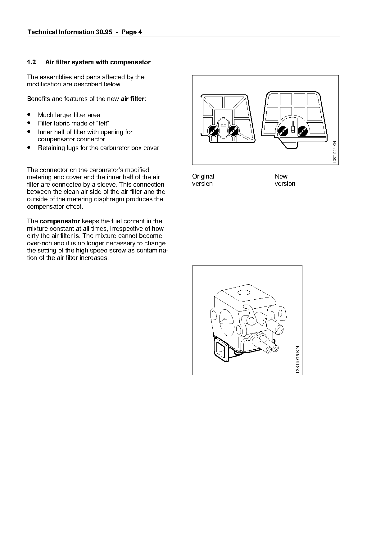
1.2=====Air filter system with compensator

The assemblies and parts affected by the
modification are described below.

Benefits and features of the new air filter:

• Much larger filter area
• Filter fabric made of "felt"
• Inner half of filter with opening for
      compensator connector

                                                                                                        138TI004 KN
• Retaining lugs for the carburetor box cover

The connector on the carburetor’s modified
metering end cover and the inner half of the air           Original             New

filter are connected by a sleeve. This connection          version              version
between the clean air side of the air filter and the
outside of the metering diaphragm produces the

compensator effect.

The FRPSHQVDWRU keeps the fuel content in the
mixture constant at all times, irrespective of how
dirty the air filter is. The mixture cannot become
over-rich and it is no longer necessary to change
the setting of the high speed screw as contamina-
tion of the air filter increases.

                                                                                          138TI005 KN
Page 5 of 8
Text of page 5 — search, copy, screen readers
Technical Information 30.95  -  Page 5

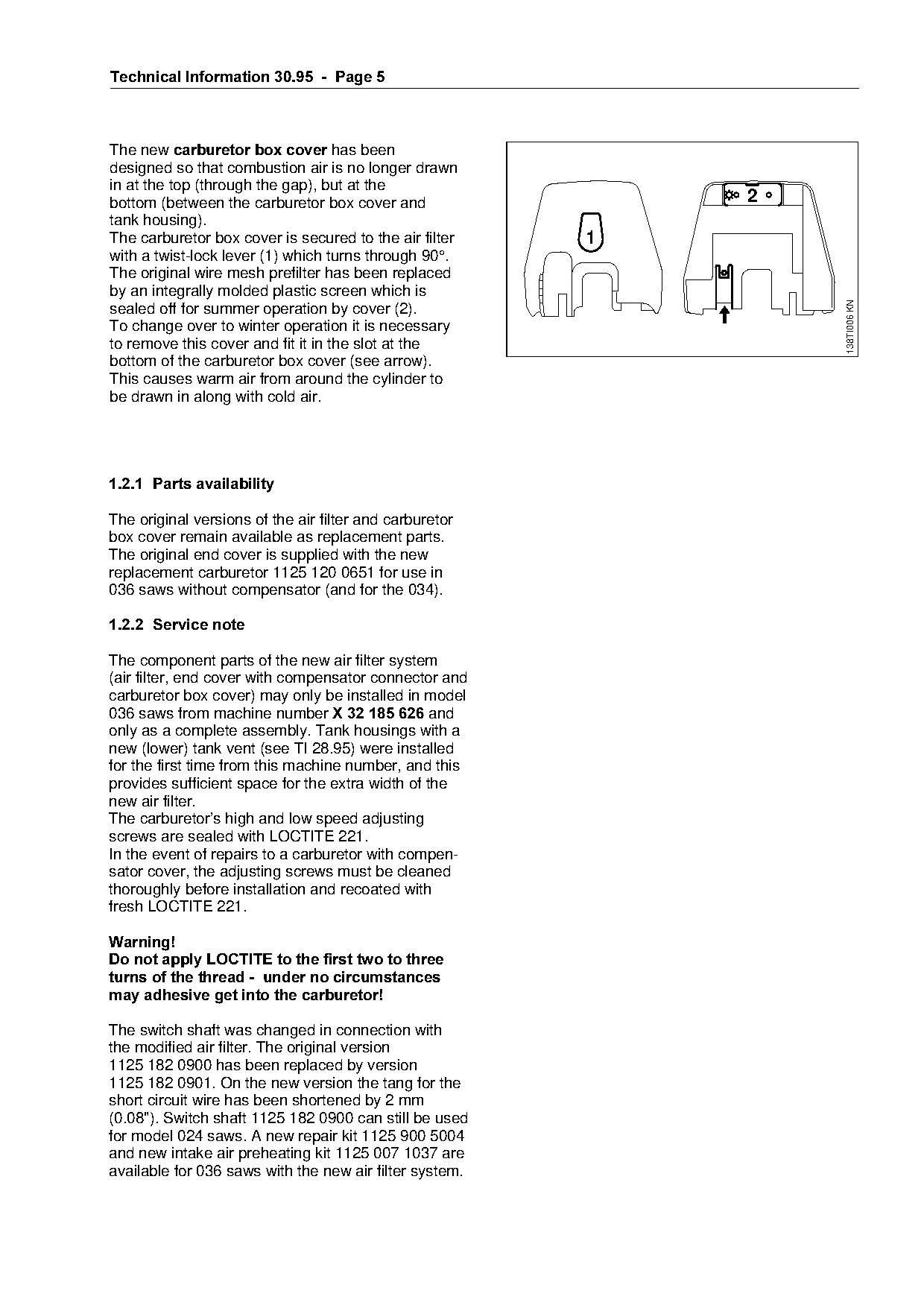
The new carburetor box cover=has been
designed so that combustion air is no longer drawn
in at the top (through the gap), but at the
bottom (between the carburetor box cover and                              2
tank housing).
The carburetor box cover is secured to the air filter          1
with a twist-lock lever (1) which turns through 90°.
The original wire mesh prefilter has been replaced
by an integrally molded plastic screen which is

                                                                              138TI006 KN
sealed off for summer operation by cover (2).
To change over to winter operation it is necessary
to remove this cover and fit it in the slot at the
bottom of the carburetor box cover (see arrow).

This causes warm air from around the cylinder to

be drawn in along with cold air.

1.2.1=Parts availability

The original versions of the air filter and carburetor
box cover remain available as replacement parts.
The original end cover is supplied with the new
replacement carburetor 1125 120 0651 for use in
036 saws without compensator (and for the 034).

1.2.2=Service note

The component parts of the new air filter system
(air filter, end cover with compensator connector and
carburetor box cover) may only be installed in model

036 saws from machine number X 32 185 626=~nd
only as a complete assembly. Tank housings with a

new (lower) tank vent (see TI 28.95) were installed
for the first time from this machine number, and this
provides sufficient space for the extra width of the
new air filter.

The carburetor’s high and low speed adjusting
screws are sealed with LOCTITE 221.

In the event of repairs to a carburetor with compen-
sator cover, the adjusting screws must be cleaned
thoroughly before installation and recoated with
fresh LOCTITE 221.

Warning!
Do not apply LOCTITE to the first two to three

turns of the thread -  under no circumstances
may adhesive get into the carburetor!

The switch shaft was changed in connection with
the modified air filter. The original version
1125 182 0900 has been replaced by version
1125 182 0901. On the new version the tang for the
short circuit wire has been shortened by 2 mm
(0.08"). Switch shaft 1125 182 0900 can still be used
for model 024 saws. A new repair kit 1125 900 5004
and new intake air preheating kit 1125 007 1037 are
available for 036 saws with the new air filter system.
Page 6 of 8
Text of page 6 — search, copy, screen readers
Technical Information 30.95  -  Page 6

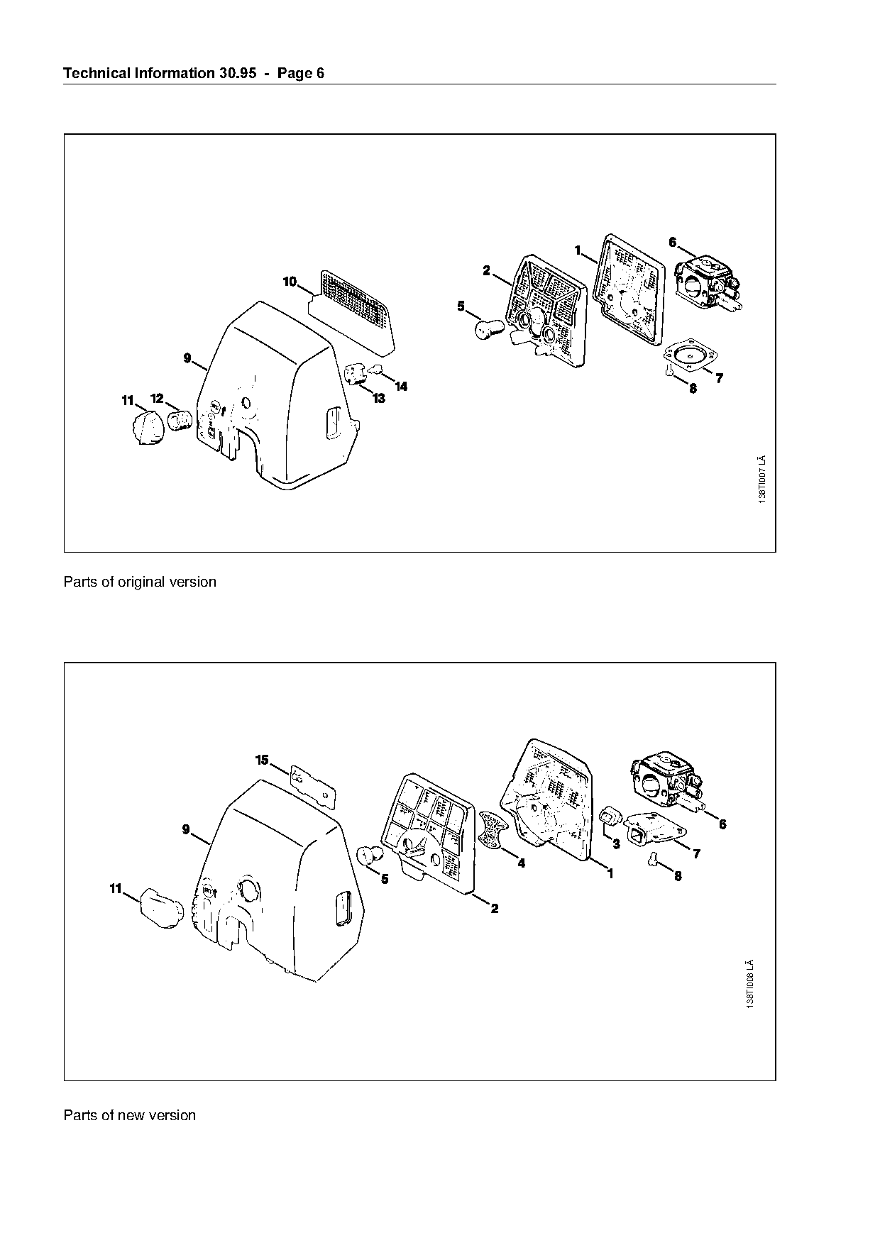
                                                                           138TI007 LÄ
Parts of original version

                                                             138TI008 LÄ

Parts of new version
Page 7 of 8
Text of page 7 — search, copy, screen readers
Technical Information 30.95  -  Page 7

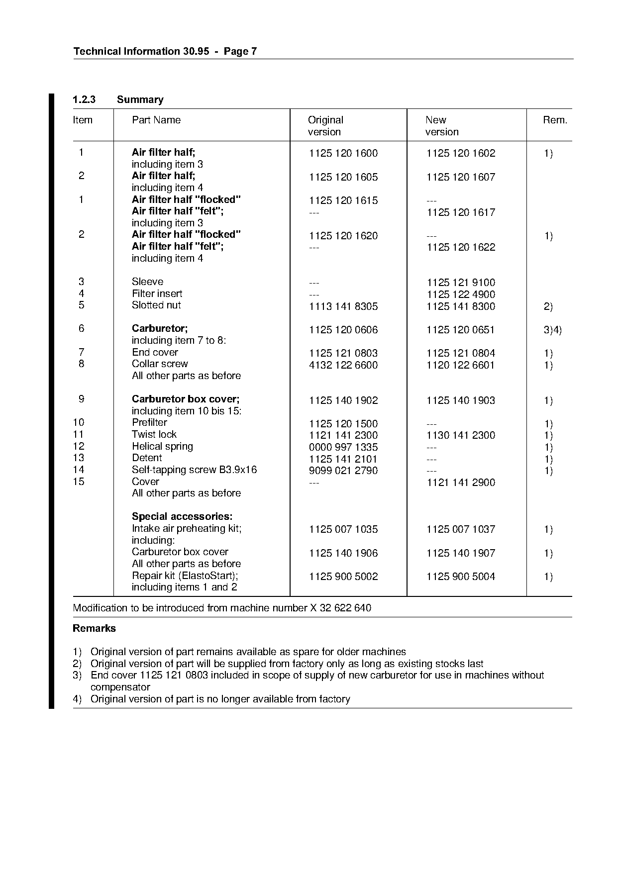
1.2.3=====Summary
Item        Part Name                            Original                 New                      Rem.
                                                 version                  version

  N=========Air filter half;======================NNOR=NOM=NSMM============NNOR=NOM=NSMO===========NF
            including item 3
 O==========Air filter half;======================NNOR=NOM=NSMR============NNOR=NOM=NSMT
            including item 4
 N==========Air filter half "flocked"=============NNOR=NOM=NSNR============JJJ
            Air filter half "felt";===============JJJ======================NNOR=NOM=NSNT
            including item 3
 O==========Air filter half "flocked"=============NNOR=NOM=NSOM============JJJ=====================NF
            Air filter half "felt"

                                                  ---                      1125 120 1622

            including item 4

 3          Sleeve                                ---                      1125 121 9100

 4          Filter insert                         ---                      1125 122 4900
 5          Slotted nut                           1113 141 8305            1125 141 8300           2)

 6          &DUEXUHWRU

                                                  1125 120 0606            1125 120 0651           3)4)
            including item 7 to 8:
 7          End cover                             1125 121 0803            1125 121 0804           1)
 8          Collar screw
            All other parts as before
                                                  4132 122 6600            1120 122 6601           1)

============Carburetor box cover
 9                                                1125 140 1902            1125 140 1903           1)
            including item 10 bis 15:
10          Prefilter                             1125 120 1500            ---                     1)

11          Twist lock                            1121 141 2300            1130 141 2300           1)
12          Helical spring                        0000 997 1335            ---                     1)
13          Detent                                1125 141 2101            ---                     1)
14          Self-tapping screw B3.9x16            9099 021 2790            ---                     1)

15          Cover                                 ---                      1121 141 2900

            All other parts as before

            Special accessories
            Intake air preheating kit;            1125 007 1035            1125 007 1037           1)

            including:
            Carburetor box cover                  1125 140 1906            1125 140 1907           1)
            All other parts as before

            Repair kit (ElastoStart);             1125 900 5002            1125 900 5004           1)
            including items 1 and 2

Modification to be introduced from machine number X 32 622 640
5HPDUNV

1) Original version of part remains available as spare for older machines
2) Original version of part will be supplied from factory only as long as existing stocks last
3) End cover 1125 121 0803 included in scope of supply of new carburetor for use in machines without
   compensator
4) Original version of part is no longer available from factory
Page 8 of 8
Text of page 8 — search, copy, screen readers
Technical Information 30.95 - Page 8
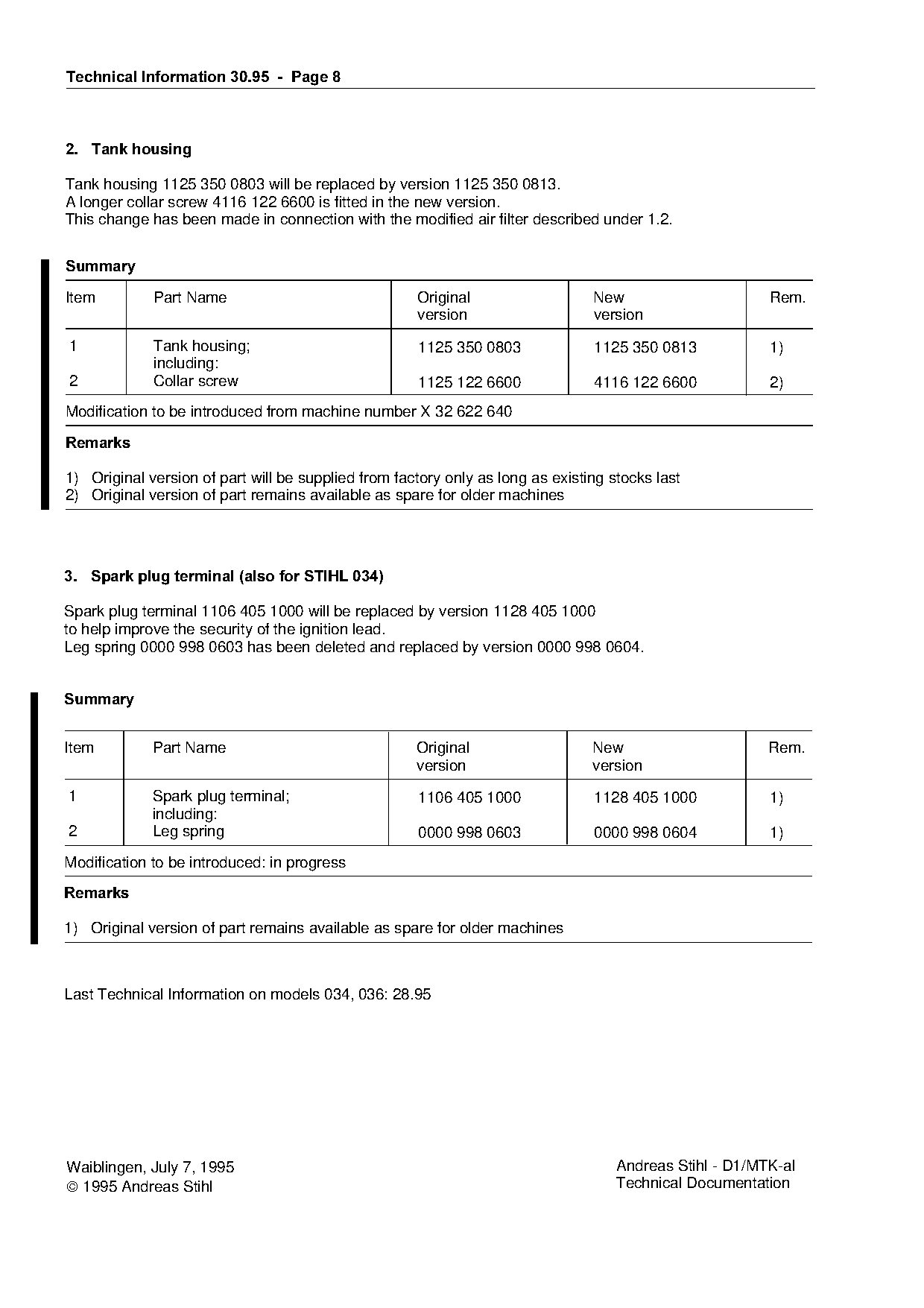
2.=Tank housing
Tank housing 1125 350 0803 will be replaced by version 1125 350 0813.
A longer collar screw 4116 122 6600 is fitted in the new version.
This change has been made in connection with the modified air filter described under 1.2.
6XPPDU\
Item Part Name Original New Rem.
version version
1 Tank housing; 1125 350 0803 1125 350 0813 1)
including:
2 Collar screw 1125 122 6600 4116 122 6600 2)
Modification to be introduced from machine number X 32 622 640
5HPDUNV
1) Original version of part will be supplied from factory only as long as existing stocks last
2) Original version of part remains available as spare for older machines
3.=Spark plug terminal =also for STIHL 034
Spark plug terminal 1106 405 1000 will be replaced by version 1128 405 1000
to help improve the security of the ignition lead.
Leg spring 0000 998 0603 has been deleted and replaced by version 0000 998 0604.
6XPPDU\
Item Part Name Original New Rem.
version version
1 Spark plug terminal; 1106 405 1000 1128 405 1000 1)
including:
2 Leg spring 0000 998 0603 0000 998 0604 1)
Modification to be introduced: in progress
5HPDUNV
1) Original version of part remains available as spare for older machines
Last Technical Information on models 034, 036: 28.95
Waiblingen, July 7, 1995 Andreas Stihl - D1/MTK-al
1995 Andreas Stihl Technical Documentation Most of these PDFs embed fonts with a shifted character map, so the text above was recovered rather than copied — read it as a faithful but imperfect transcription, and treat the page image above each block as the authority where the two disagree — the figures exist only there, because they are vector drawings that text extraction cannot keep.