Technical Information · issue 31 of 1995
Air filter system with compensator; decompression
Model 026 chainsaws from machine number
Full text
Page 1 of 6
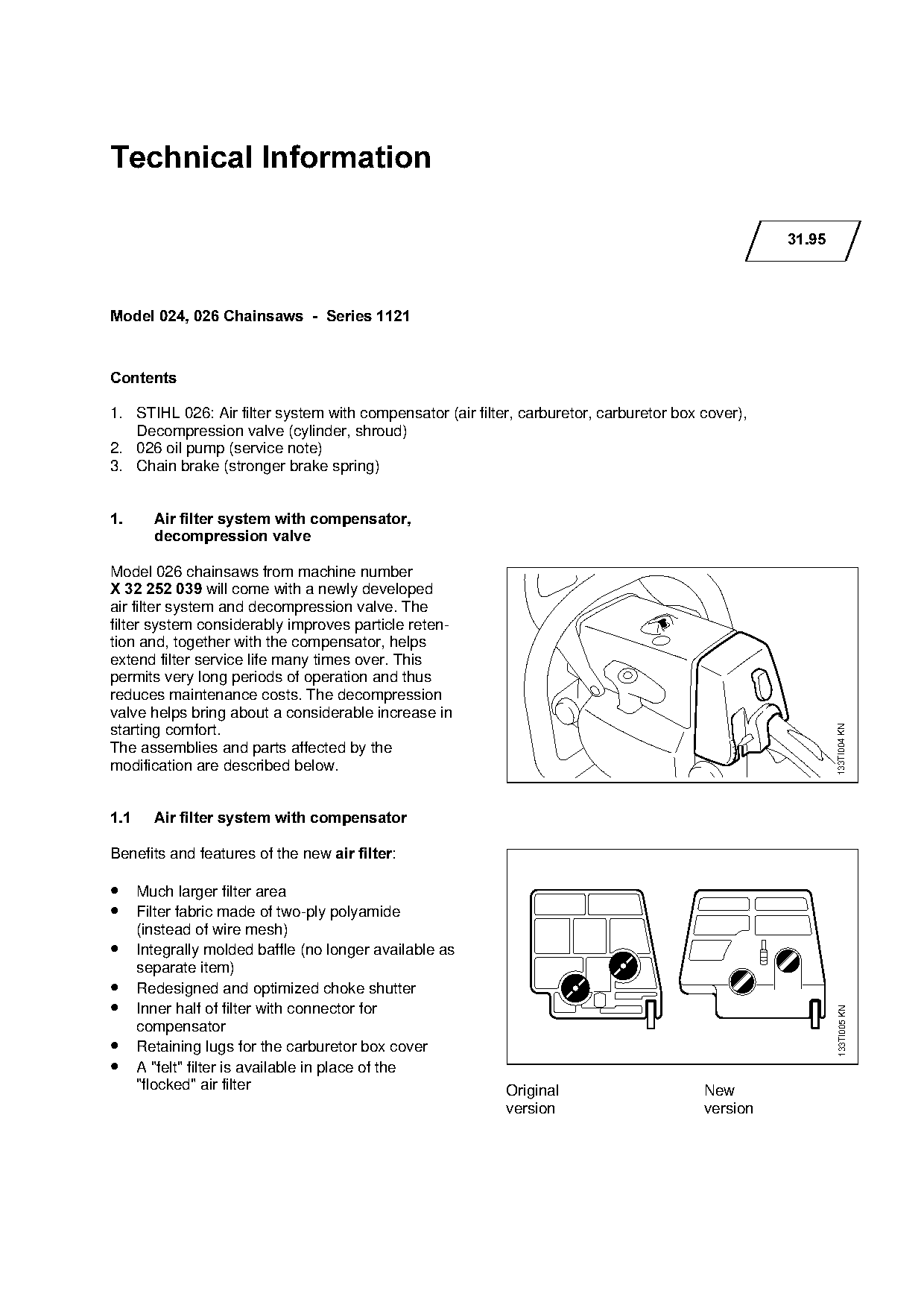
Text of page 1 — search, copy, screen readers
Technical Information

                                                                                                   31.95

Model 024, 026 Chainsaws  -  Series 1121

&RQWHQWV

1. STIHL 026: Air filter system with compensator (air filter, carburetor, carburetor box cover),
   Decompression valve (cylinder, shroud)

2. 026 oil pump (service note)
3. Chain brake (stronger brake spring)

1.=======Air filter system with compensator,
         decompression valve

Model 026 chainsaws from machine number
X 32 252 039=will come with a newly developed
air filter system and decompression valve. The
filter system considerably improves particle reten-

tion and, together with the compensator, helps
extend filter service life many times over. This
permits very long periods of operation and thus
reduces maintenance costs. The decompression

valve helps bring about a considerable increase in

                                                                                                           133TI004 KN
starting comfort.

The assemblies and parts affected by the
modification are described below.

1.1======Air filter system with compensator

Benefits and features of the new air filter:

• Much larger filter area
• Filter fabric made of two-ply polyamide

      (instead of wire mesh)
• Integrally molded baffle (no longer available as

      separate item)
• Redesigned and optimized choke shutter
• Inner half of filter with connector for
                                                                                                           133TI005 KN

      compensator
• Retaining lugs for the carburetor box cover
• A "felt" filter is available in place of the
      "flocked" air filter                                 Original                      New
                                                           version                       version
Page 2 of 6
Text of page 2 — search, copy, screen readers
Technical Information 31.95  -  Page 2

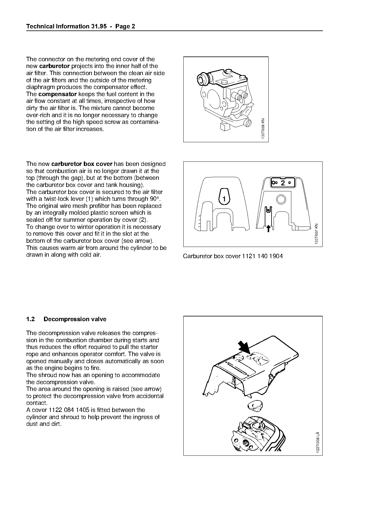
The connector on the metering end cover of the
new FDUEXUHWRU projects into the inner half of the
air filter. This connection between the clean air side
of the air filters and the outside of the metering
diaphragm produces the compensator effect.
The FRPSHQVDWRU keeps the fuel content in the
air flow constant at all times, irrespective of how
dirty the air filter is. The mixture cannot become
over-rich and it is no longer necessary to change

                                                                                   133TI006 KN
the setting of the high speed screw as contamina-
tion of the air filter increases.

The new carburetor box cover=has been designed
so that combustion air is no longer drawn it at the

top (through the gap), but at the bottom (between
the carburetor box cover and tank housing).                                                      2
The carburetor box cover is secured to the air filter

with a twist-lock lever (1) which turns through 90°.                  1
The original wire mesh prefilter has been replaced
by an integrally molded plastic screen which is
sealed off for summer operation by cover (2).                   fo

                                                                                                     133TI007 KN
To change over to winter operation it is necessary
to remove this cover and fit it in the slot at the
bottom of the carburetor box cover (see arrow).
This causes warm air from around the cylinder to be

drawn in along with cold air.                            Carburetor box cover 1121 140 1904

1.2===Decompression valve

The decompression valve releases the compres-

sion in the combustion chamber during starts and
thus reduces the effort required to pull the starter
rope and enhances operator comfort. The valve is

opened manually and closes automatically as soon
as the engine begins to fire.
The shroud now has an opening to accommodate

the decompression valve.
The area around the opening is raised (see arrow)
to protect the decompression valve from accidental
contact.
A cover 1122 084 1405 is fitted between the
cylinder and shroud to help prevent the ingress of
dust and dirt.
                                                                                                        133TI008 LÄ
Page 3 of 6
Text of page 3 — search, copy, screen readers
Technical Information 31.95  -  Page 3

1.3===Parts availability

The original versions of the air filter and carburetor
box cover remain available as replacement parts.
The original end cover is supplied with the new
replacement carburetor 1121 120 0650 for use in
026 saws without compensator (and for the 024).
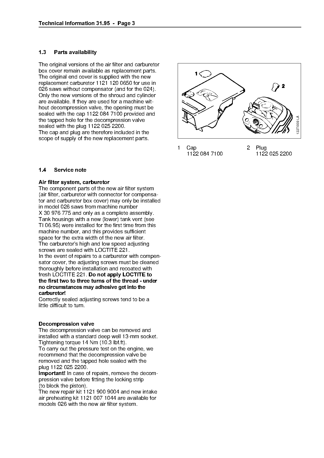
Only the new versions of the shroud and cylinder
are available. If they are used for a machine wit-
hout decompression valve, the opening must be
sealed with the cap 1122 084 7100 provided and

                                                                                                 133TI009 LÄ
the tapped hole for the decompression valve
sealed with the plug 1122 025 2200.

The cap and plug are therefore included in the

scope of supply of the new replacement parts.
                                                         1   Cap             2   Plug

                                                             1122 084 7100       1122 025 2200

1.4===Service note

Air filter system, carburetor
The component parts of the new air filter system
(air filter, carburetor with connector for compensa-
tor and carburetor box cover) may only be installed
in model 026 saws from machine number
X 30 976 775 and only as a complete assembly.
Tank housings with a new (lower) tank vent (see

TI 06.95) were installed for the first time from this
machine number, and this provides sufficient
space for the extra width of the new air filter.
The carburetor’s high and low speed adjusting

screws are sealed with LOCTITE 221.
In the event of repairs to a carburetor with compen-

sator cover, the adjusting screws must be cleaned
thoroughly before installation and recoated with
fresh=il`qfqb=OONK=Do not apply LOCTITE to
the first two to three turns of the thread - under

no circumstances may adhesive get into the
carburetor!

Correctly sealed adjusting screws tend to be a
little difficult to turn.

Decompression valve
The decompression valve can be removed and
installed with a standard deep well 13-mm socket.

Tightening torque 14 Nm (10.3 lbf.ft).
To carry out the pressure test on the engine, we
recommend that the decompression valve be
removed and the tapped hole sealed with the
plug 1122 025 2200.
Important!=fn case of repairs, remove the decom-
pression valve before fitting the locking strip
(to block the piston).
The new repair kit 1121 900 9004 and new intake
air preheating kit 1121 007 1044 are available for
models 026 with the new air filter system.
Page 4 of 6
Text of page 4 — search, copy, screen readers
Technical Information 31.95  -  Page 4

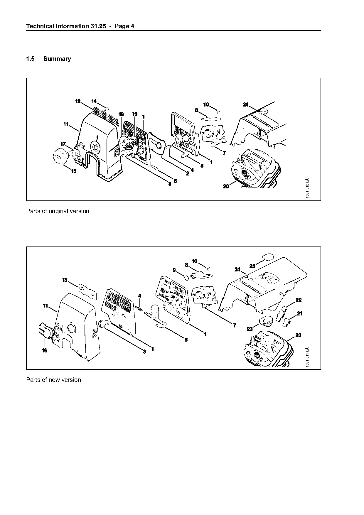
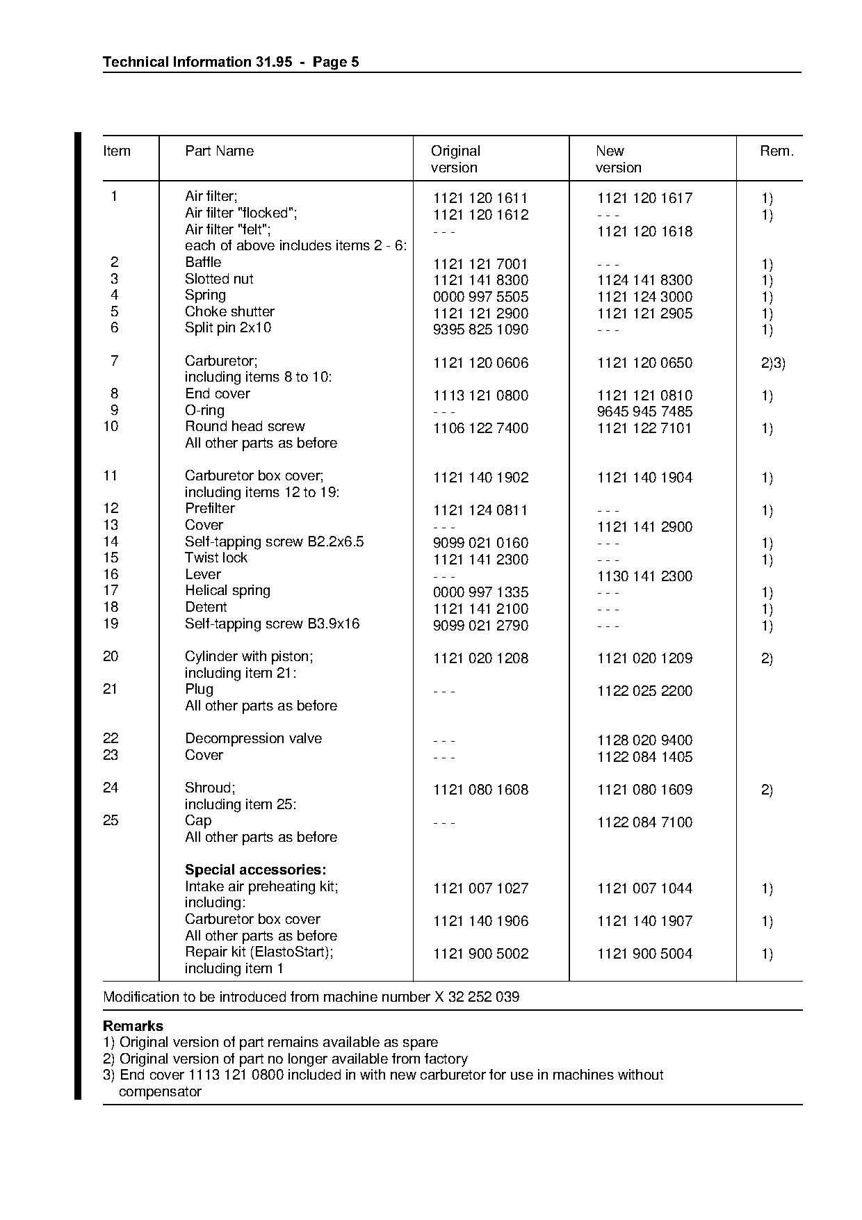
1.5===Summary

                                                             133TI010 LÄ
Parts of original version

                                                             133TI011 LÄ

Parts of new version
Page 5 of 6
Text of page 5 — search, copy, screen readers
Technical Information 31.95  -  Page 5

Item        Part Name                             Original                 New             Rem.
                                                  version                  version
 1          Air filter;                           1121 120 1611            1121 120 1617   1)
            Air filter "flocked";                 1121 120 1612            ---             1)
            Air filter "felt";                    ---                      1121 120 1618
            each of above includes items 2 - 6:
 2          Baffle                                1121 121 7001            ---             1)
 3          Slotted nut                           1121 141 8300            1124 141 8300   1)
 4          Spring                                0000 997 5505            1121 124 3000   1)
 5          Choke shutter                         1121 121 2900            1121 121 2905   1)
 6          Split pin 2x10                        9395 825 1090            ---             1)

 7          Carburetor;                           1121 120 0606            1121 120 0650   2)3)
            including items 8 to 10:
 8          End cover                             1113 121 0800            1121 121 0810   1)

 9          O-ring                                ---                      9645 945 7485
10          Round head screw                      1106 122 7400            1121 122 7101   1)
            All other parts as before

11          Carburetor box cover;                 1121 140 1902            1121 140 1904   1)
            including items 12 to 19:
12
13
            Prefilter
            Cover                                 ---
                                                  1121 124 0811            ---
                                                                           1121 141 2900
                                                                                           1)

14          Self-tapping screw B2.2x6.5           9099 021 0160            ---             1)
15          Twist lock                            1121 141 2300            ---             1)
16          Lever                                 ---                      1130 141 2300
17          Helical spring                        0000 997 1335            ---             1)

18          Detent                                1121 141 2100            ---             1)
19          Self-tapping screw B3.9x16            9099 021 2790            ---             1)

20          Cylinder with piston;                 1121 020 1208            1121 020 1209   2)

            including item 21:

21          Plug                                  ---                      1122 025 2200
            All other parts as before

22          Decompression valve                   ---                      1128 020 9400

23          Cover                                 ---                      1122 084 1405

24          Shroud;

                                                  1121 080 1608            1121 080 1609   2)
            including item 25:
25          Cap                                   ---                      1122 084 7100
            All other parts as before

            Special accessories
            Intake air preheating kit;            1121 007 1027            1121 007 1044   1)

            including:
            Carburetor box cover                  1121 140 1906            1121 140 1907   1)
            All other parts as before
            Repair kit (ElastoStart);             1121 900 5002            1121 900 5004   1)
            including item 1
Modification to be introduced from machine number X 32 252 039
5HPDUNV
1) Original version of part remains available as spare
2) Original version of part no longer available from factory
3) End cover 1113 121 0800 included in with new carburetor for use in machines without
   compensator
Page 6 of 6
Text of page 6 — search, copy, screen readers
Technical Information 31.95  -  Page 6

2.=====026 oil pump

Before installing a new oil pump and when
servicing the saw, check lubrication of the pump
piston and replenish it as follows if necessary:

• Pry the plastic plug out of the pump body
• Apply a little grease to the piston control face
• Refit the plug.

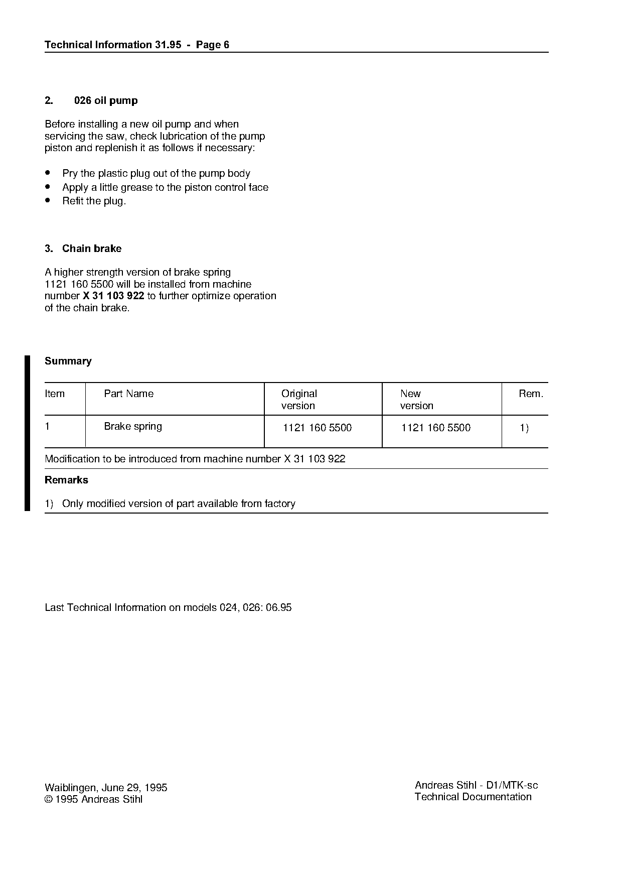
3.=Chain brake

A higher strength version of brake spring
1121 160 5500 will be installed from machine
number X 31 103 922=to further optimize operation

of the chain brake.

6XPPDU\
Item         Part Name                               Original         New                     Rem.
                                                     version          version
1            Brake spring                            1121 160 5500    1121 160 5500           1)

Modification to be introduced from machine number X 31 103 922

5HPDUNV

1) Only modified version of part available from factory

Last Technical Information on models 024, 026: 06.95

Waiblingen, June 29, 1995                                                Andreas Stihl - D1/MTK-sc
© 1995 Andreas Stihl                                                     Technical Documentation
Most of these PDFs embed fonts with a shifted character map, so the text above was recovered rather than copied — read it as a faithful but imperfect transcription, and treat the page image above each block as the authority where the two disagree — the figures exist only there, because they are vector drawings that text extraction cannot keep.