Technical Information · issue 33 of 1995
Electronic speed governor; 19mm a/f mounting screw
Model TS 510, 760 Cut-off Machines - Series 4205
IssueTI 33/1995
From serial 24 073 218
Part changes (1)
| Was | Becomes | What the bulletin says |
|---|---|---|
| 1111 400 1303 | 1111 400 1301 | The original ignition module 1111 400 1303 will be replaced by ignition coil 1111 400 1301 and a separate trigger unit 4205 400 1000. |
Full text
Page 1 of 2
Text of page 1 — search, copy, screen readers
Technical Information

                                                                                               33.95

Model TS 510, 760 Cut-off Machines  -  Series 4205

&RQWHQWV

1. Electronic speed governor (ignition coil and trigger unit)
2. Mounting screws, 19 mm a/f (cast arm), changeover to Torx screws, tool kit

1.=Electronic speed governor

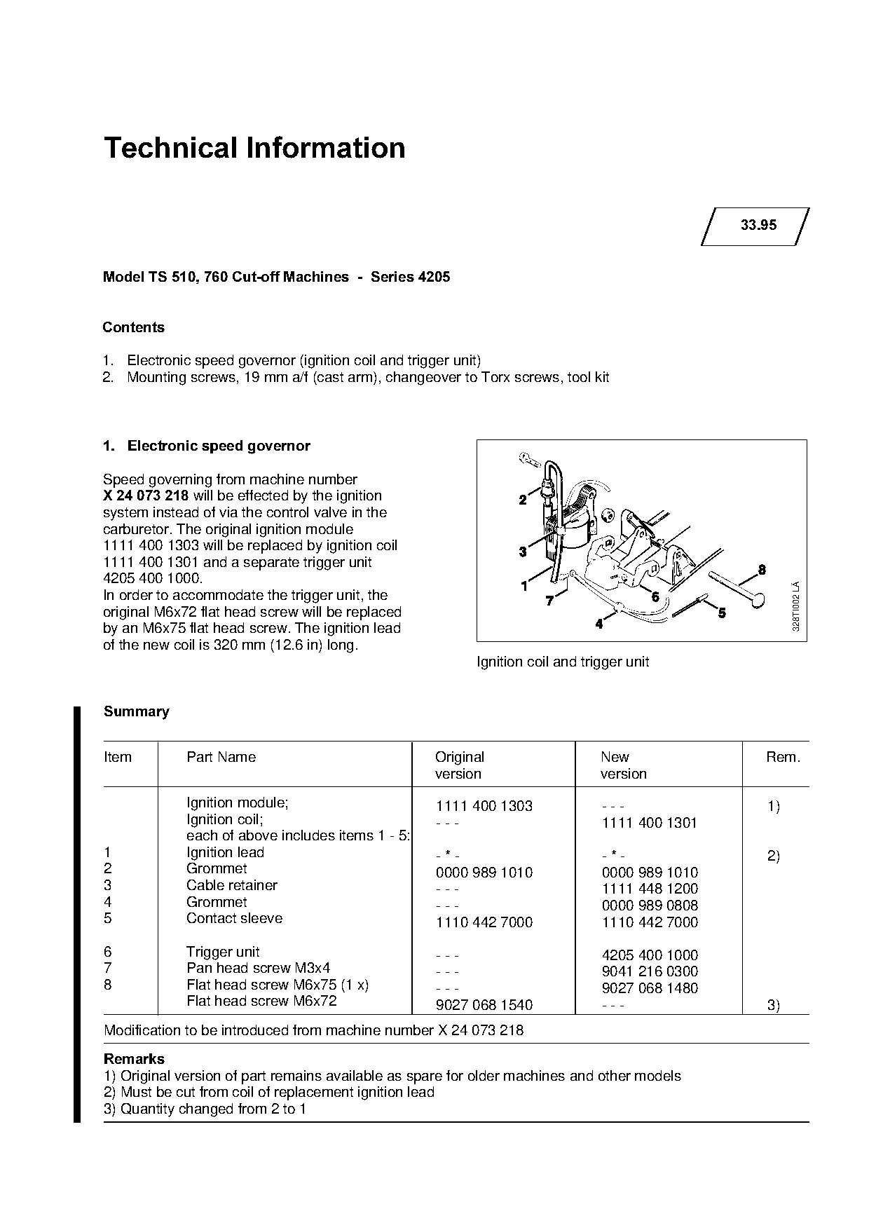
Speed governing from machine number
X 24 073 218=will be effected by the ignition
system instead of via the control valve in the
carburetor. The original ignition module
1111 400 1303 will be replaced by ignition coil
1111 400 1301 and a separate trigger unit
4205 400 1000.

                                                                                                       328TI002 LÄ
In order to accommodate the trigger unit, the

original M6x72 flat head screw will be replaced
by an M6x75 flat head screw. The ignition lead
of the new coil is 320 mm (12.6 in) long.
                                                          Ignition coil and trigger unit

6XPPDU\

Item         Part Name                             Original                    New                Rem.
                                                   version                     version

             Ignition module;                      1111 400 1303               ---                1)
             Ignition coil;                        ---                         1111 400 1301
             each of above includes items 1 - 5:
1            Ignition lead

                                                   -*-                         -*-                2)
2            Grommet                               0000 989 1010               0000 989 1010
3            Cable retainer                        ---                         1111 448 1200
4            Grommet

                                                   ---                         0000 989 0808
5            Contact sleeve                        1110 442 7000               1110 442 7000

6            Trigger unit                          ---                         4205 400 1000
7            Pan head screw M3x4                   ---                         9041 216 0300
8            Flat head screw M6x75 (1 x)           ---                         9027 068 1480
             Flat head screw M6x72                 9027 068 1540               ---                3)
Modification to be introduced from machine number X 24 073 218
5HPDUNV
1) Original version of part remains available as spare for older machines and other models
2) Must be cut from coil of replacement ignition lead
3) Quantity changed from 2 to 1
Page 2 of 2
Text of page 2 — search, copy, screen readers
Technical Information 33.95  -  Page 2

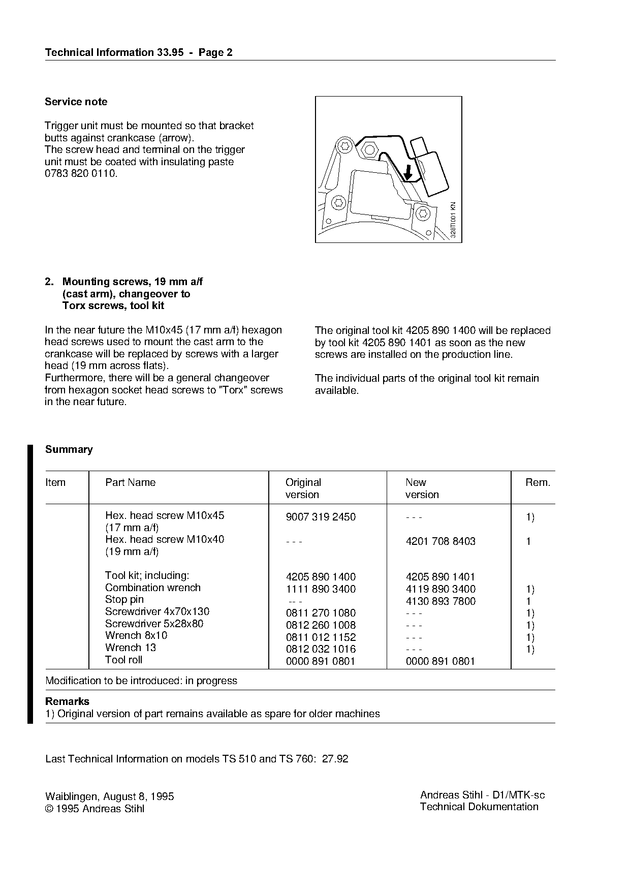
Service note

Trigger unit must be mounted so that bracket
butts against crankcase (arrow).
The screw head and terminal on the trigger
unit must be coated with insulating paste
0783 820 0110.

                                                                                          328TI001 KN

2.=Mounting screws, 19 mm a/f
====cast arm=, changeover to

   Torx screws, tool kit

In the near future the M10x45 (17 mm a/f) hexagon          The original tool kit 4205 890 1400 will be replaced

head screws used to mount the cast arm to the              by tool kit 4205 890 1401 as soon as the new
crankcase will be replaced by screws with a larger         screws are installed on the production line.
head (19 mm across flats).
Furthermore, there will be a general changeover
from hexagon socket head screws to "Torx" screws
                                                           The individual parts of the original tool kit remain
                                                           available.
in the near future.

6XPPDU\

Item         Part Name                               Original                  New                         Rem.

                                                     version                   version

             Hex. head screw M10x45                  9007 319 2450              ---                        1)
             (17 mm a/f)
             Hex. head screw M10x40                  ---                        4201 708 8403              1

             (19 mm a/f)

             Tool kit; including:

                                                     4205 890 1400              4205 890 1401
             Combination wrench                      1111 890 3400              4119 890 3400              1)
             Stop pin                                -- -                       4130 893 7800              1
             Screwdriver 4x70x130                    0811 270 1080              ---                        1)

             Screwdriver 5x28x80                     0812 260 1008              ---                        1)
             Wrench 8x10                             0811 012 1152              ---                        1)
             Wrench 13                               0812 032 1016              ---                        1)

             Tool roll                               0000 891 0801              0000 891 0801
Modification to be introduced: in progress
5HPDUNV
1) Original version of part remains available as spare for older machines

Last Technical Information on models TS 510 and TS 760: 27.92

Waiblingen, August 8, 1995                                                         Andreas Stihl - D1/MTK-sc
© 1995 Andreas Stihl                                                               Technical Dokumentation
Most of these PDFs embed fonts with a shifted character map, so the text above was recovered rather than copied — read it as a faithful but imperfect transcription, and treat the page image above each block as the authority where the two disagree — the figures exist only there, because they are vector drawings that text extraction cannot keep.