Technical Information · issue 37 of 1995
New cut-off saw
IssueTI 37/1995
Full text
Page 1 of 12
Text of page 1 — search, copy, screen readers
Technical Information

                                                                                               37.95

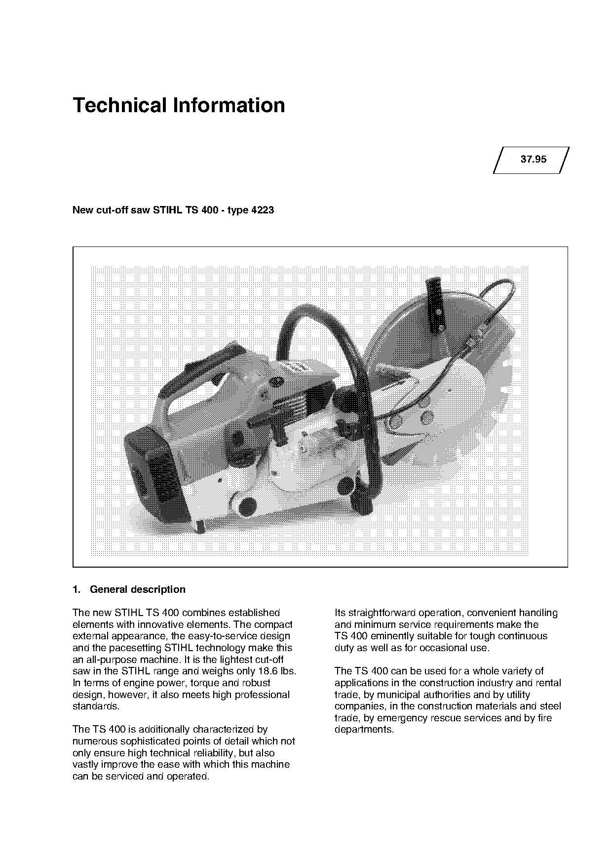
New cut-off saw STIHL TS 400 - type 4223

1. General description

The new STIHL TS 400 combines established            Its straightforward operation, convenient handling
elements with innovative elements. The compact       and minimum service requirements make the
external appearance, the easy-to-service design      TS 400 eminently suitable for tough continuous

and the pacesetting STIHL technology make this       duty as well as for occasional use.
an all-purpose machine. It is the lightest cut-off
saw in the STIHL range and weighs only 18.6 lbs.     The TS 400 can be used for a whole variety of
In terms of engine power, torque and robust          applications in the construction industry and rental
design, however, it also meets high professional     trade, by municipal authorities and by utility
standards.                                           companies, in the construction materials and steel
                                                     trade, by emergency rescue services and by fire
The TS 400 is additionally characterized by          departments.
numerous sophisticated points of detail which not
only ensure high technical reliability, but also
vastly improve the ease with which this machine
can be serviced and operated.
Page 2 of 12
Text of page 2 — search, copy, screen readers
Technical Information 37.95 - Page 2

2.   Equipment

The STIHL TS 400 is equipped with the newly developed long-term air filter system with compensator, the
STIHL quickstart system with ElastoStart and decompression valve, the AV handle system, semi-automatic
V-belt tensioner, fuel tank with integrated expansion reservoir, electronic magneto-ignition system with
speed limitation, and a new, light aluminium guard.

3.   Technical description

Air filter system and compensator

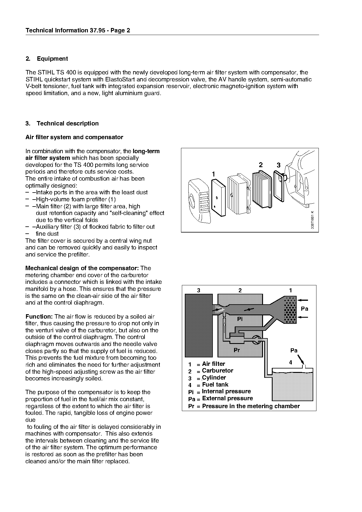
In combination with the compensator, the long-term
air filter system which has been specially
developed for the TS 400 permits long service                                       2      3
periods and therefore cuts service costs.

                                                                    1
The entire intake of combustion air has been
optimally designed:
– –Intake ports in the area with the least dust

– –High-volume foam prefilter (1)
– –Main filter (2) with large filter area, high
     dust retention capacity and "self-cleaning" effect            fo

                                                                                                           338TI001 K
     due to the vertical folds
– –Auxiliary filter (3) of flocked fabric to filter out
– fine dust
The filter cover is secured by a central wing nut
and can be removed quickly and easily to inspect

and service the prefilter.

Mechanical design of the compensator: The
metering chamber end cover of the carburetor

                                                                        ;;

includes a connector which is linked with the intake

manifold by a hose. This ensures that the pressure             3             2                 1
is the same on the clean-air side of the air filter
and at the control diaphragm.
                                                                                                      Pa

Function: The air flow is reduced by a soiled air                            Pi
filter, thus causing the pressure to drop not only in
the venturi valve of the carburetor, but also on the

outside of the control diaphragm. The control
diaphragm moves outwards and the needle valve
closes partly so that the supply of fuel is reduced.                       Pr                   Pa

This prevents the fuel mixture from becoming too
rich and eliminates the need for further adjustment              Air filter
                                                            1 = Luftfilter                      4
of the high-speed adjusting screw as the air filter              Carburetor
                                                            2 = Vergaser

becomes increasingly soiled.                                     Cylinder
                                                            3 = Zylinder
                                                                 Fuel tank
                                                            4 = Kraftstofftank
The purpose of the compensator is to keep the                    Internal pressure
                                                            Pi = Innendruck
proportion of fuel in the fuel/air mix constant,                 External pressure
                                                            Pa = Außendruck
regardless of the extent to which the air filter is              Pressure
                                                            Pr = Druck      in the metering chamber
                                                                         im Regelraum
fouled. The rapid, tangible loss of engine power
due
 to fouling of the air filter is delayed considerably in
machines with compensator. This also extends
the intervals between cleaning and the service life
of the air filter system. The optimum performance
is restored as soon as the prefilter has been
cleaned and/or the main filter replaced.
Page 3 of 12
Text of page 3 — search, copy, screen readers
Technical Information 37.95 - Page 3

The compensator is designed to reduce costs and
allows the machine to be used more effectively.
In addition, it ensures that the fuel/air mix remains
constant.

STIHL - Quickstart system for easy starting

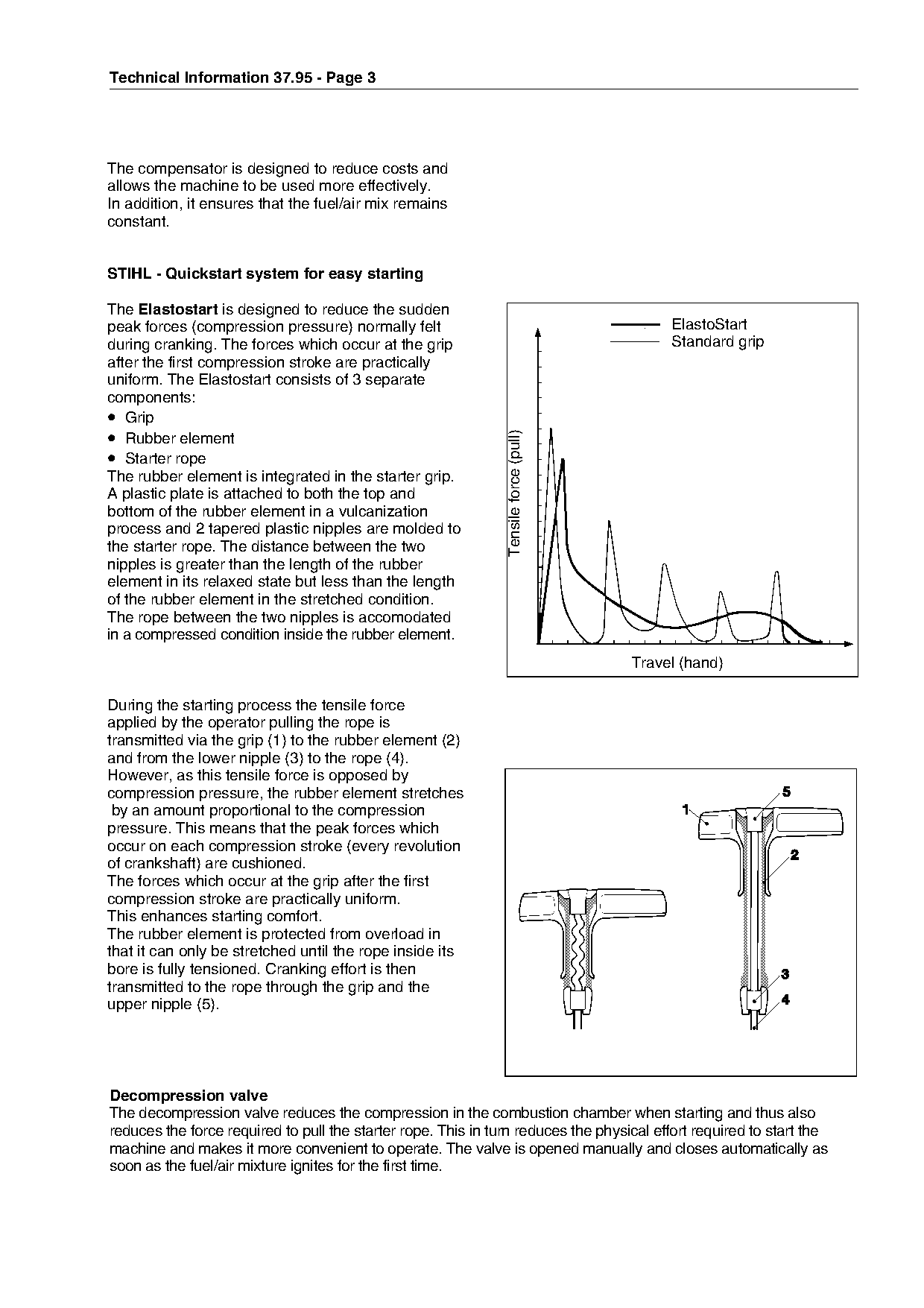
The Elastostart is designed to reduce the sudden
peak forces (compression pressure) normally felt                                                ElastoStart
during cranking. The forces which occur at the grip                                             Standard grip
after the first compression stroke are practically

uniform. The Elastostart consists of 3 separate

components:
• Grip
• Rubber element

                                                               Tensile force (pull)

• Starter rope
The rubber element is integrated in the starter grip.

A plastic plate is attached to both the top and
bottom of the rubber element in a vulcanization
process and 2 tapered plastic nipples are molded to
the starter rope. The distance between the two
nipples is greater than the length of the rubber
element in its relaxed state but less than the length
of the rubber element in the stretched condition.
The rope between the two nipples is accomodated
in a compressed condition inside the rubber element.

                                                                                           Travel (hand)

During the starting process the tensile force

applied by the operator pulling the rope is

transmitted via the grip (1) to the rubber element (2)
and from the lower nipple (3) to the rope (4).
However, as this tensile force is opposed by
compression pressure, the rubber element stretches

 by an amount proportional to the compression
pressure. This means that the peak forces which

occur on each compression stroke (every revolution
of crankshaft) are cushioned.
The forces which occur at the grip after the first
compression stroke are practically uniform.

This enhances starting comfort.
The rubber element is protected from overload in
that it can only be stretched until the rope inside its

bore is fully tensioned. Cranking effort is then
transmitted to the rope through the grip and the
upper nipple (5).

Decompression valve
The decompression valve reduces the compression in the combustion chamber when starting and thus also
reduces the force required to pull the starter rope. This in turn reduces the physical effort required to start the
machine and makes it more convenient to operate. The valve is opened manually and closes automatically as
soon as the fuel/air mixture ignites for the first time.
Page 4 of 12
Text of page 4 — search, copy, screen readers
Technical Information 37.95 - Page 4

Mechanical design and function

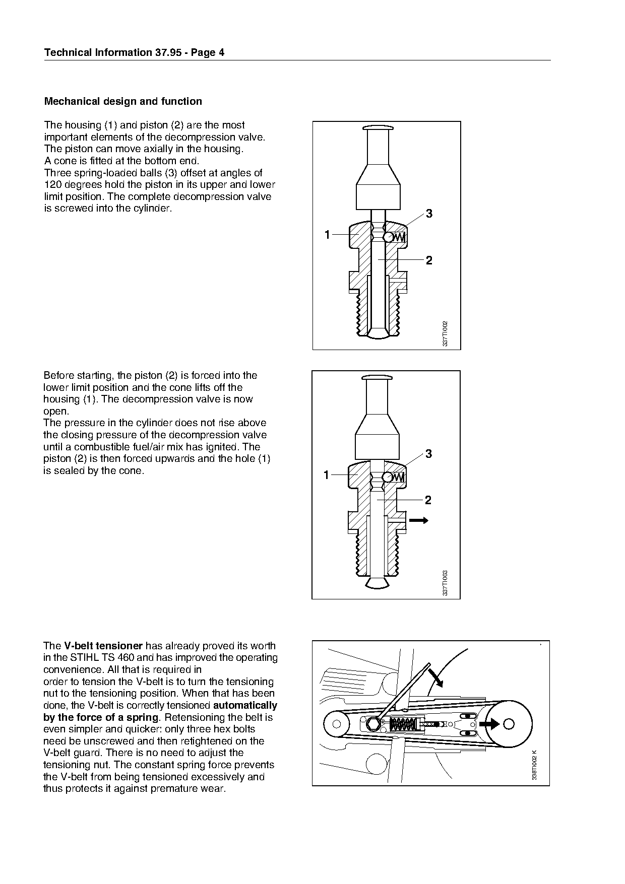
The housing (1) and piston (2) are the most
important elements of the decompression valve.
The piston can move axially in the housing.
A cone is fitted at the bottom end.
Three spring-loaded balls (3) offset at angles of
120 degrees hold the piston in its upper and lower
limit position. The complete decompression valve
is screwed into the cylinder.
                                                                   3
                                                         1


                                                                       337TI002
Before starting, the piston (2) is forced into the
lower limit position and the cone lifts off the
housing (1). The decompression valve is now
open.
The pressure in the cylinder does not rise above

the closing pressure of the decompression valve
until a combustible fuel/air mix has ignited. The
piston (2) is then forced upwards and the hole (1)                 3
is sealed by the cone.                                   1


                                                                       337TI003

The V-belt tensioner has already proved its worth

in the STIHL TS 460 and has improved the operating
convenience. All that is required in
order to tension the V-belt is to turn the tensioning
nut to the tensioning position. When that has been
done, the V-belt is correctly tensioned automatically
by the force of a spring. Retensioning the belt is
even simpler and quicker: only three hex bolts
need be unscrewed and then retightened on the
V-belt guard. There is no need to adjust the
                                                                                  338TI002 K

tensioning nut. The constant spring force prevents
the V-belt from being tensioned excessively and
thus protects it against premature wear.
Page 5 of 12
Text of page 5 — search, copy, screen readers
Technical Information 37.95 - Page 5

The fuel tank has a capacity of 1.56 pints.
The large filler port is located on the top of the
housing so that it can be filled easily and without
tilting the machine.                                                       2
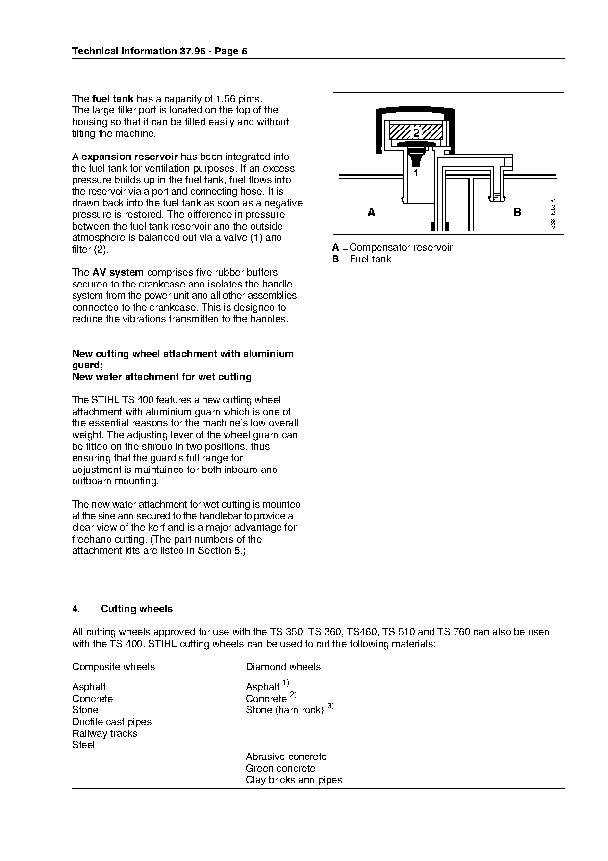
A expansion reservoir has been integrated into
the fuel tank for ventilation purposes. If an excess                       1
pressure builds up in the fuel tank, fuel flows into
the reservoir via a port and connecting hose. It is

                                                                                                         338TI003 K
drawn back into the fuel tank as soon as a negative
pressure is restored. The difference in pressure                  A                           B
between the fuel tank reservoir and the outside
atmosphere is balanced out via a valve (1) and

filter (2).                                                A = Compensator reservoir

                                                           B = Fuel tank
The AV system comprises five rubber buffers
secured to the crankcase and isolates the handle

system from the power unit and all other assemblies
connected to the crankcase. This is designed to
reduce the vibrations transmitted to the handles.

New cutting wheel attachment with aluminium
guard;
New water attachment for wet cutting
The STIHL TS 400 features a new cutting wheel
attachment with aluminium guard which is one of

the essential reasons for the machine’s low overall
weight. The adjusting lever of the wheel guard can
be fitted on the shroud in two positions, thus
ensuring that the guard’s full range for

adjustment is maintained for both inboard and
outboard mounting.

The new water attachment for wet cutting is mounted
at the side and secured to the handlebar to provide a
clear view of the kerf and is a major advantage for

freehand cutting. (The part numbers of the
attachment kits are listed in Section 5.)

4.    Cutting wheels

All cutting wheels approved for use with the TS 350, TS 360, TS460, TS 510 and TS 760 can also be used

with the TS 400. STIHL cutting wheels can be used to cut the following materials:

Composite wheels                        Diamond wheels
Asphalt                                 Asphalt 1)
Concrete                                Concrete 2)
Stone                                   Stone (hard rock) 3)
Ductile cast pipes
Railway tracks
Steel
                                        Abrasive concrete
                                        Green concrete
                                        Clay bricks and pipes
Page 6 of 12
Text of page 6 — search, copy, screen readers
Technical Information 37.95 - Page 6

1) All types and blends of asphalt commonly used for building construction and road
   construction, including the respective aggregates, as well as green concrete and screed topping
2) Cast stones of all types commonly used for and building construction, including light
   reinforced concrete
3) Natural stones of every hardness, including granite stones of the hardest wear class, cast stones
   and concrete

5.   Special accessories

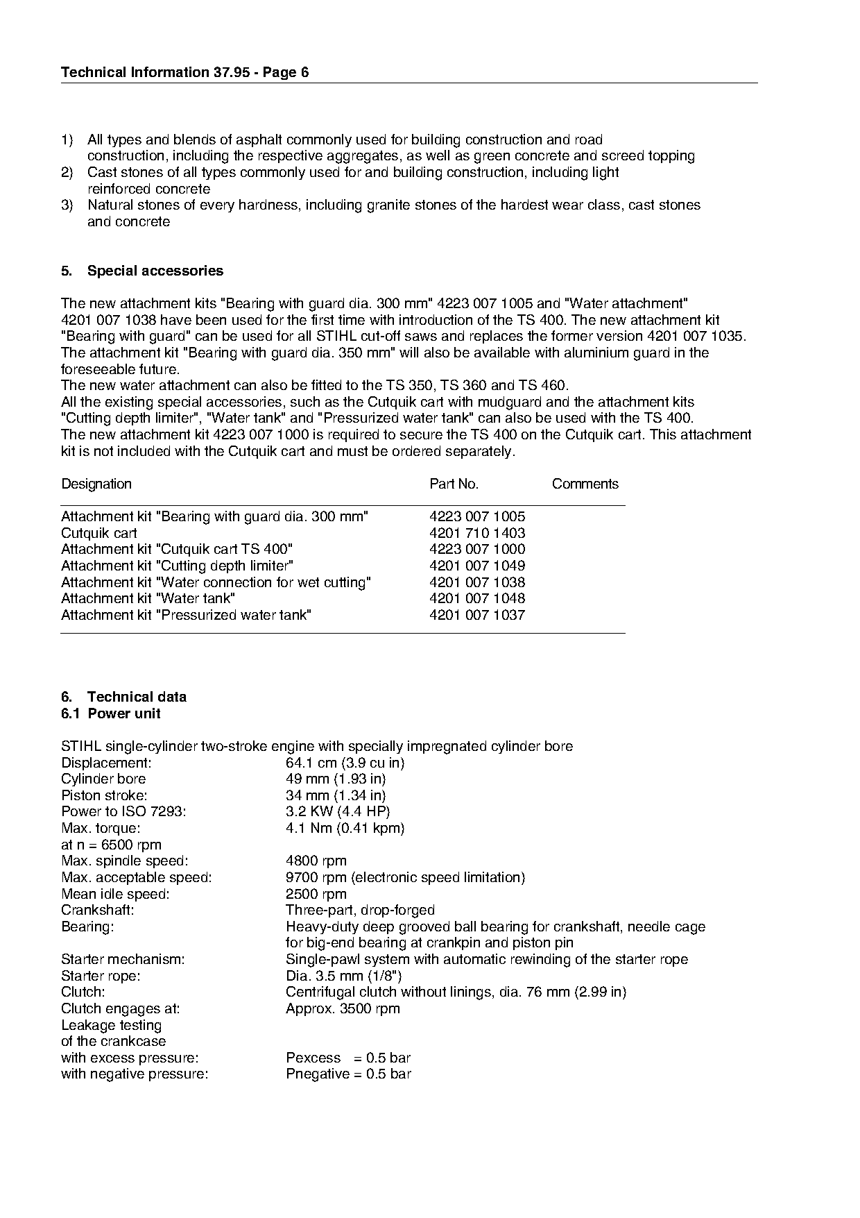
The new attachment kits "Bearing with guard dia. 300 mm" 4223 007 1005 and "Water attachment"
4201 007 1038 have been used for the first time with introduction of the TS 400. The new attachment kit
"Bearing with guard" can be used for all STIHL cut-off saws and replaces the former version 4201 007 1035.

The attachment kit "Bearing with guard dia. 350 mm" will also be available with aluminium guard in the

foreseeable future.
The new water attachment can also be fitted to the TS 350, TS 360 and TS 460.
All the existing special accessories, such as the Cutquik cart with mudguard and the attachment kits

"Cutting depth limiter", "Water tank" and "Pressurized water tank" can also be used with the TS 400.
The new attachment kit 4223 007 1000 is required to secure the TS 400 on the Cutquik cart. This attachment
kit is not included with the Cutquik cart and must be ordered separately.

Designation                                              Part No.           Comments

Attachment kit "Bearing with guard dia. 300 mm"
Cutquik cart
                                                         4223 007 1005
                                                         4201 710 1403
Attachment kit "Cutquik cart TS 400"                     4223 007 1000
Attachment kit "Cutting depth limiter"                   4201 007 1049
Attachment kit "Water connection for wet cutting"        4201 007 1038

Attachment kit "Water tank"                              4201 007 1048
Attachment kit "Pressurized water tank"                  4201 007 1037

6. Technical data
6.1 Power unit

STIHL single-cylinder two-stroke engine with specially impregnated cylinder bore

Displacement:                      64.1 cm (3.9 cu in)
Cylinder bore                      49 mm (1.93 in)

Piston stroke:                     34 mm (1.34 in)
Power to ISO 7293:                 3.2 KW (4.4 HP)
Max. torque:                       4.1 Nm (0.41 kpm)
at n = 6500 rpm

Max. spindle speed:                4800 rpm
Max. acceptable speed:             9700 rpm (electronic speed limitation)
Mean idle speed:                   2500 rpm

Crankshaft:                        Three-part, drop-forged
Bearing:                           Heavy-duty deep grooved ball bearing for crankshaft, needle cage
                                   for big-end bearing at crankpin and piston pin
Starter mechanism:                 Single-pawl system with automatic rewinding of the starter rope
Starter rope:                      Dia. 3.5 mm (1/8")
Clutch:                            Centrifugal clutch without linings, dia. 76 mm (2.99 in)
Clutch engages at:                 Approx. 3500 rpm
Leakage testing
of the crankcase
with excess pressure:              Pexcess = 0.5 bar
with negative pressure:            Pnegative = 0.5 bar
Page 7 of 12
Text of page 7 — search, copy, screen readers
Technical Information 37.95 - Page 7

6.2 Fuel system

Carburetor:                         All-position diaphragm carburetor
                                    with integral fuel pump
Adjustment
High-speed adjusting screw H:       Approx. 1 turn open
Low-speed adjusting screw L:        Approx. 1 turn open
                                    (Adjustment starts with the screws closed)
Leakage testing of the carburetor
with excess pressure:               Pexcess = 0.8 bar
Fuel tank capacity:                 0.74 l (1.56 pt))
Fuel mix:                           Branded mid-grade gasoline (89 octane) and branded two-stroke engine oil
Mixing ratio:                       1:50 for STIHL two-stroke engine oil 1:50

Air filter:                         Prefilter (foam)

                                    Large main filter (paper)
                                    Auxiliary filter (flocked plastic fabric)

6.3 Ignition system

Basic principle:                    Transistorized (contactless) magneto-ignition system with

                                    integrated control unit and electronic speed limitation
Air gap:                            0.15...0.3 mm (0.006 – 0.012 in)
Ignition timing:                    1.6 ... 2.2 mm (0.063 – 0.087 in) before TDC at 8000 rpm
Spark plug (suppressed):            Bosch WSR 6 F or
                                    NGK BPMR 7 A
Electrode gap:                      0.5 mm (0.02 in)
Spark plug thread:                  M 14 x 1.25
Thread length:                      9.5 mm (0.37 in)

Heat range value:                   200
Length of ignition lead:            370 mm (145/8 in)

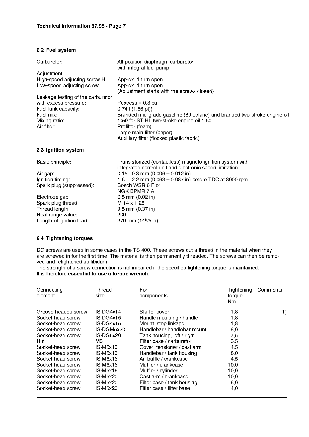
6.4 Tightening torques

DG screws are used in some cases in the TS 400. These screws cut a thread in the material when they
are screwed in for the first time. The material is then permanently threaded. The screws can then be remo-
ved and retightened ad libidum.
The strength of a screw connection is not impaired if the specified tightening torque is maintained.

It is therefore essential to use a torque wrench.

Connecting                 Thread            For                                    Tightening   Comments
element                    size              components                             torque
                                                                                    Nm

Groove-headed screw        IS-DG4x14         Starter cover                           1,8                     1)
Socket-head screw          IS-DG4x15         Handle moulding / handle                1,8

Socket-head screw          IS-DG4x15         Mount, stop linkage                     1,8
Socket-head screw          IS-DGM5x20        Handlebar / handlebar mount             8,0
Socket-head screw          IS-DG5x20         Tank housing, left / right              7,5
Nut                        M5                Filter base / carburetor                3,5
Socket-head screw          IS-M5x16          Cover, tensioner / cast arm             4,5
Socket-head screw          IS-M5x16          Handlebar / tank housing                8,0
Socket-head screw          IS-M5x16          Air baffle / crankcase                  4,5
Socket-head screw          IS-M5x16          Muffler / crankcase                    10,0
Socket-head screw          IS-M5x16          Muffler / cylinder                     10,0
Socket-head screw          IS-M5x20          Cast arm / crankcase                   10,0
Socket-head screw          IS-M5x20          Filter base / tank housing              6,0
Socket-head screw          IS-M5x20          Fitler case / filter base               4,0
Page 8 of 12
Text of page 8 — search, copy, screen readers
Technical Information 37.95 - Page 8

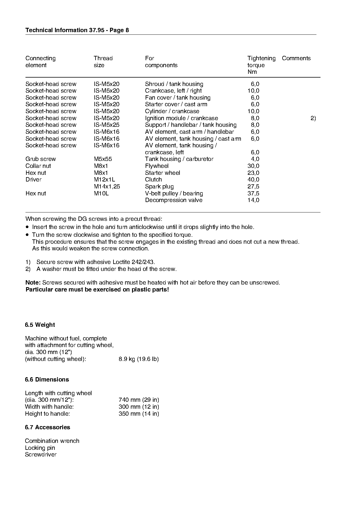
Connecting                  Thread            For                                   Tightening   Comments
element                     size              components                            torque
                                                                                    Nm

Socket-head screw           IS-M5x20          Shroud / tank housing                  6,0
Socket-head screw           IS-M5x20          Crankcase, left / right               10,0
Socket-head screw           IS-M5x20          Fan cover / tank housing               6,0
Socket-head screw           IS-M5x20          Starter cover / cast arm               6,0
Socket-head screw           IS-M5x20          Cylinder / crankcase                  10,0
Socket-head screw           IS-M5x20          Ignition module / crankcase            8,0                2)
Socket-head screw           IS-M5x25          Support / handlebar / tank housing     8,0
Socket-head screw           IS-M6x16          AV element, cast arm / handlebar       6,0
Socket-head screw           IS-M6x16          AV element, tank housing / cast arm    6,0

Socket-head screw           IS-M6x16          AV element, tank housing /

                                              crankcase, left                        6,0
Grub screw                  M5x55             Tank housing / carburetor              4,0
Collar nut                  M8x1              Flywheel                              30,0

Hex nut                     M8x1              Starter wheel                         23,0
Driver                      M12x1L            Clutch                                40,0
                            M14x1,25          Spark plug                            27,5

Hex nut                     M10L              V-belt pulley / bearing               37,5
                                              Decompression valve                   14,0

When screwing the DG screws into a precut thread:
• Insert the screw in the hole and turn anticlockwise until it drops slightly into the hole.
• Turn the screw clockwise and tighten to the specified torque.
  This procedure ensures that the screw engages in the existing thread and does not cut a new thread.

  As this would weaken the screw connection.

1) Secure screw with adhesive Loctite 242/243.
2) A washer must be fitted under the head of the screw.

Note: Screws secured with adhesive must be heated with hot air before they can be unscrewed.

Particular care must be exercised on plastic parts!

6.5 Weight

Machine without fuel, complete
with attachment for cutting wheel,
dia. 300 mm (12")

(without cutting wheel):           8.9 kg (19.6 lb)

6.6 Dimensions

Length with cutting wheel
(dia. 300 mm/12"):                   740 mm (29 in)
Width with handle:                   300 mm (12 in)
Height to handle:                    350 mm (14 in)

6.7 Accessories

Combination wrench
Locking pin
Screwdriver
Page 9 of 12
Text of page 9 — search, copy, screen readers
Technical Information 37.95 - Page 9

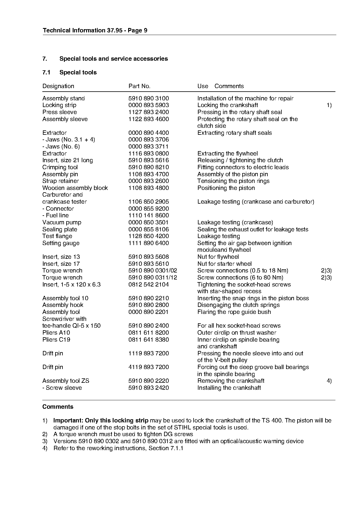
7.     Special tools and service accessories

7.1    Special tools

Designation                    Part No.                 Use    Comments
Assembly stand                 5910 890 3100            Installation of the machine for repair
Locking strip                  0000 893 5903            Locking the crankshaft                           1)
Press sleeve                   1127 893 2400            Pressing in the rotary shaft seal
Assembly sleeve                1122 893 4600            Protecting the rotary shaft seal on the
                                                        clutch side
Extractor                      0000 890 4400            Extracting rotary shaft seals
- Jaws (No. 3.1 + 4)           0000 893 3706

- Jaws (No. 6)                 0000 893 3711

Extractor                      1116 893 0800            Extracting the flywheel
Insert, size 21 long           5910 893 5616            Releasing / tightening the clutch
Crimping tool                  5910 890 8210            Fitting connectors to electric leads

Assembly pin                   1108 893 4700            Assembly of the piston pin
Strap retainer                 0000 893 2600            Tensioning the piston rings
Wooden assembly block          1108 893 4800            Positioning the piston

Carburetor and
crankcase tester               1106 850 2905            Leakage testing (crankcase and carburetor)
- Connector                    0000 855 9200
- Fuel line
Vacuum pump
                               1110 141 8600
                               0000 850 3501
                                                        Leakage testing (crankcase)
Sealing plate                  0000 855 8106            Sealing the exhaust outlet for leakage tests
Test flange                    1128 850 4200            Leakage testing
Setting gauge                  1111 890 6400            Setting the air gap between ignition
                                                        moduleand flywheel

Insert, size 13                5910 893 5608            Nut for flywheel
Insert, size 17                5910 893 5610            Nut for starter wheel
Torque wrench                  5910 890 0301/02         Screw connections (0.5 to 18 Nm)               2)3)

Torque wrench                  5910 890 0311/12         Screw connections (6 to 80 Nm)                 2)3)
Insert, 1-5 x 120 x 6.3        0812 542 2104            Tightening the socket-head screws

                                                        with star-shaped recess
Assembly tool 10               5910 890 2210            Inserting the snap rings in the piston boss
Assembly hook                  5910 890 2800            Disengaging the clutch springs
Assembly tool                  0000 890 2201            Flaring the rope guide bush

Screwdriver with
tee-handle QI-5 x 150          5910 890 2400            For all hex socket-head screws

Pliers A10                     0811 611 8200            Outer circlip on thrust washer
Pliers C19                     0811 641 8380            Inner circlip on spindle bearing
                                                        and crankshaft
Drift pin                      1119 893 7200            Pressing the needle sleeve into and out

                                                        of the V-belt pulley
Drift pin                      4119 893 7200            Forcing out the deep groove ball bearings
                                                        in the spindle bearing

Assembly tool ZS               5910 890 2220            Removing the crankshaft                         4)
- Screw sleeve                 5910 893 2420            Installing the crankshaft

Comments

1) Important: Only this locking strip may be used to lock the crankshaft of the TS 400. The piston will be
   damaged if one of the stop bolts in the set of STIHL special tools is used.
2) A torque wrench must be used to tighten DG screws
3) Versions 5910 890 0302 and 5910 890 0312 are fitted with an optical/acoustic warning device
4) Refer to the reworking instructions, Section 7.1.1
Page 10 of 12
Text of page 10 — search, copy, screen readers
Technical Information 37.95 - Page 10

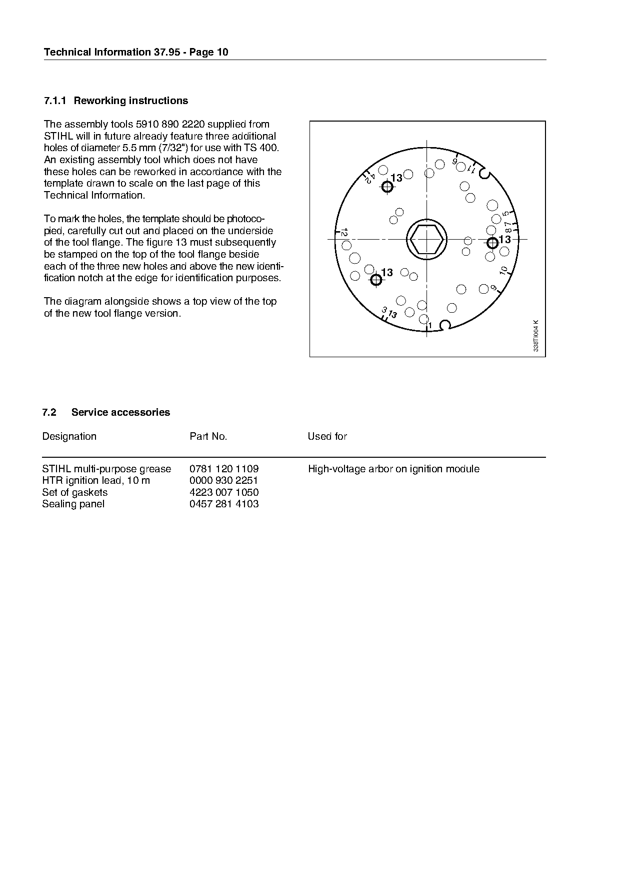
7.1.1 Reworking instructions

The assembly tools 5910 890 2220 supplied from
STIHL will in future already feature three additional
holes of diameter 5.5 mm (7/32") for use with TS 400.
An existing assembly tool which does not have                                            6
                                                                                             11
these holes can be reworked in accordance with the                        4
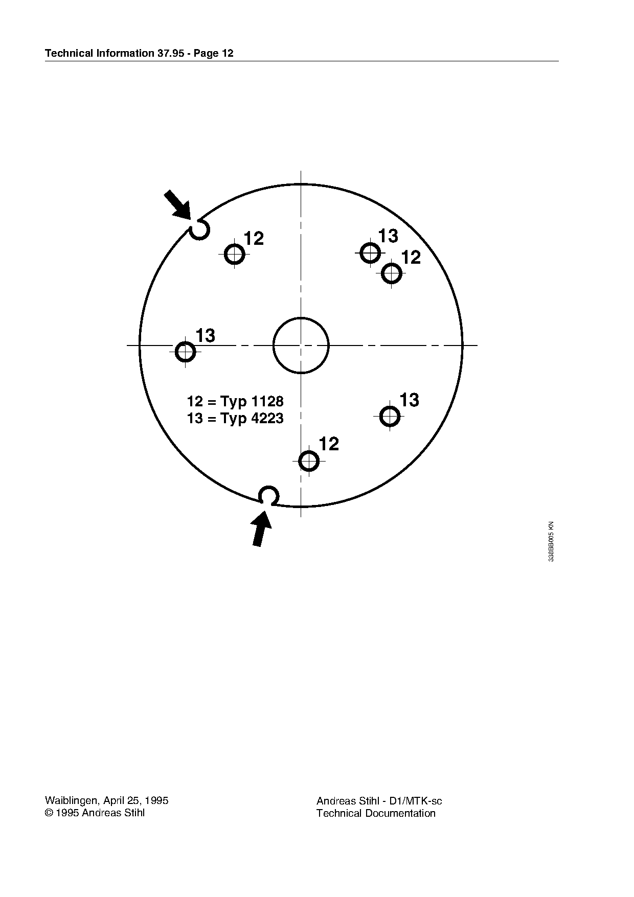
template drawn to scale on the last page of this
                                                                      2        13
Technical Information.

                                                                                                       87 5
To mark the holes, the template should be photoco-
pied, carefully cut out and placed on the underside

                                                                12
of the tool flange. The figure 13 must subsequently                                                   13

be stamped on the top of the tool flange beside

each of the three new holes and above the new identi-

                                                                                                      10
fication notch at the edge for identification purposes.                       13

                                                                                                  9
The diagram alongside shows a top view of the top
                                                                              31
of the new tool flange version.                                                 3

                                                                                                              338TI004 K
                                                                                    1

7.2   Service accessories

Designation                      Part No.                 Used for

STIHL multi-purpose grease       0781 120 1109            High-voltage arbor on ignition module

HTR ignition lead, 10 m          0000 930 2251
Set of gaskets                   4223 007 1050

Sealing panel                    0457 281 4103
Page 11 of 12
Text of page 11 — search, copy, screen readers
Technical Information 37.95 - Page 11

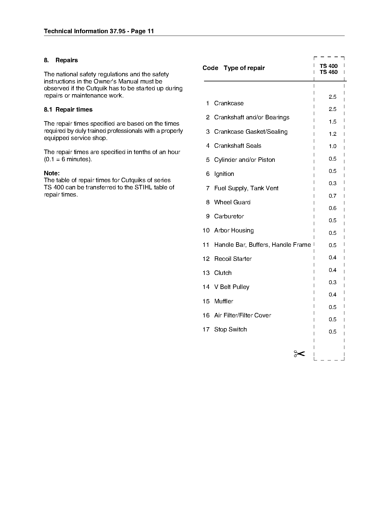
8.   Repairs
                                                         Code Type of repair                    TS 400
The national safety regulations and the safety                                                  TS 460
instructions in the Owner’s Manual must be
observed if the Cutquik has to be started up during
repairs or maintenance work.                                                                      2.5
                                                          1 Crankcase
8.1 Repair times                                                                                  2.5
                                                          2 Crankshaft and/or Bearings
The repair times specified are based on the times                                                 1.5
required by duly trained professionals with a properly    3 Crankcase Gasket/Sealing              1.2
equipped service shop.
                                                          4 Crankshaft Seals                      1.0

The repair times are specified in tenths of an hour

(0.1 = 6 minutes).                                        5 Cylinder and/or Piston                0.5

Note:                                                                                             0.5
                                                          6 Ignition

The table of repair times for Cutquiks of series                                                  0.3
TS 400 can be transferred to the STIHL table of           7 Fuel Supply, Tank Vent
repair times.                                                                                     0.7

                                                          8 Wheel Guard
                                                                                                  0.6
                                                          9 Carburetor
                                                         10 Arbor Housing
                                                                                                  0.5

                                                                                                  0.5
                                                         11 Handle Bar, Buffers, Handle Frame     0.5

                                                         12 Recoil Starter                        0.4

                                                                                                  0.4
                                                         13 Clutch
                                                                                                  0.3

                                                         14 V Belt Pulley
                                                                                                  0.4

                                                         15 Muffler
                                                                                                  0.5
                                                         16 Air Filter/Filter Cover
                                                                                                  0.5

                                                         17 Stop Switch                           0.5

                                                                                         ✂
Page 12 of 12
Text of page 12 — search, copy, screen readers
Technical Information 37.95 - Page 12

                                        12                   13


                              12 = Typ 1128                      13
                              13 = Typ 4223


                                                                              338BB005 KN

Waiblingen, April 25, 1995                       Andreas Stihl - D1/MTK-sc
© 1995 Andreas Stihl                             Technical Documentation
Most of these PDFs embed fonts with a shifted character map, so the text above was recovered rather than copied — read it as a faithful but imperfect transcription, and treat the page image above each block as the authority where the two disagree — the figures exist only there, because they are vector drawings that text extraction cannot keep.