Technical Information · issue 43 of 1995
New cut-off saw
IssueTI 43/1995
Full text
Page 1 of 12
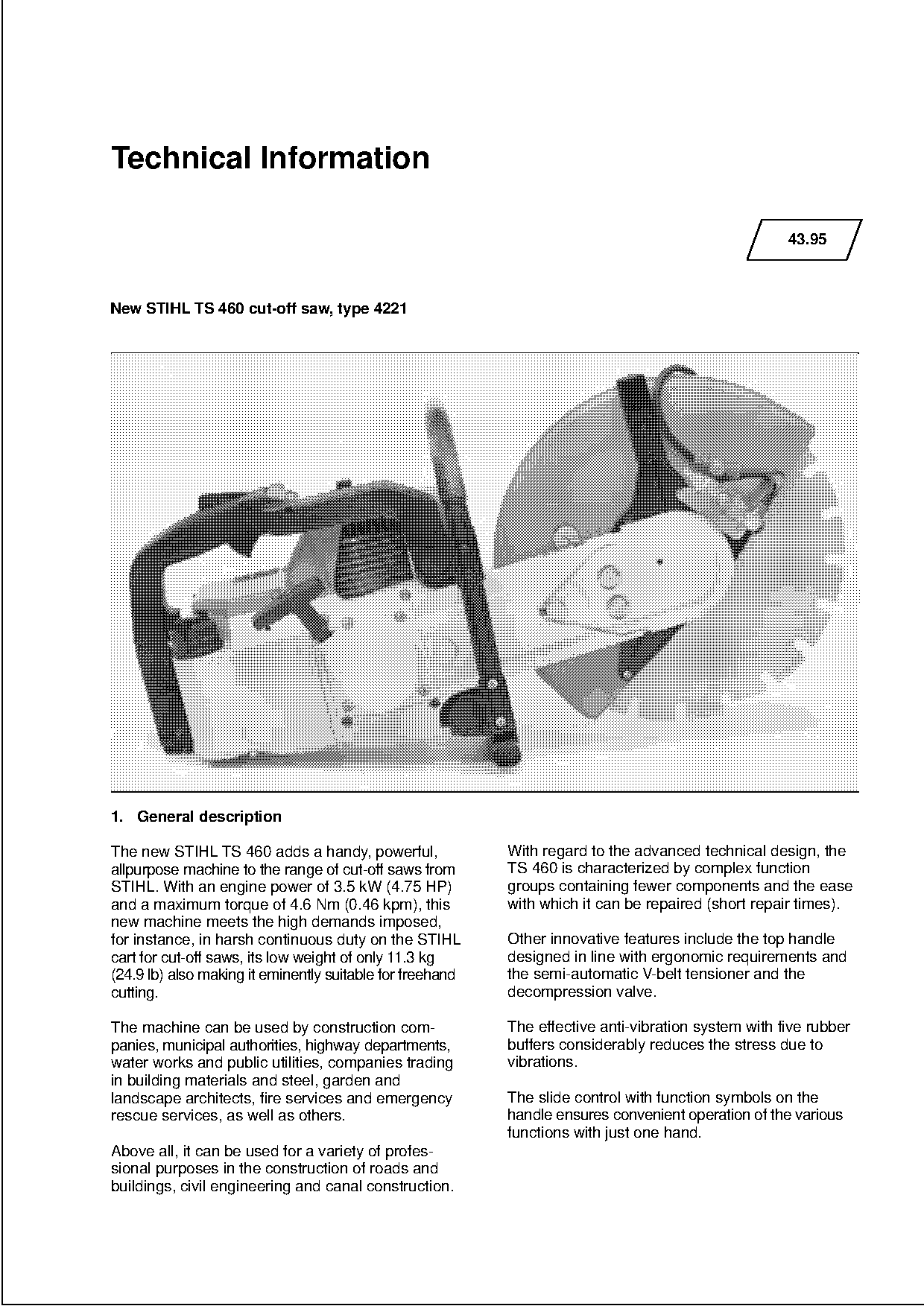
Text of page 1 — search, copy, screen readers
Technical Information

                                                                                                     43.95

New STIHL TS 460 cut-off saw, type 4221

1. General description

The new STIHL TS 460 adds a handy, powerful,               With regard to the advanced technical design, the
allpurpose machine to the range of cut-off saws from       TS 460 is characterized by complex function
STIHL. With an engine power of 3.5 kW (4.75 HP)            groups containing fewer components and the ease
and a maximum torque of 4.6 Nm (0.46 kpm), this            with which it can be repaired (short repair times).

new machine meets the high demands imposed,
for instance, in harsh continuous duty on the STIHL        Other innovative features include the top handle
cart for cut-off saws, its low weight of only 11.3 kg      designed in line with ergonomic requirements and

(24.9 lb) also making it eminently suitable for freehand   the semi-automatic V-belt tensioner and the
cutting.                                                   decompression valve.

The machine can be used by construction com-               The effective anti-vibration system with five rubber
panies, municipal authorities, highway departments,        buffers considerably reduces the stress due to
water works and public utilities, companies trading        vibrations.
in building materials and steel, garden and
landscape architects, fire services and emergency          The slide control with function symbols on the
rescue services, as well as others.                        handle ensures convenient operation of the various
                                                           functions with just one hand.
Above all, it can be used for a variety of profes-
sional purposes in the construction of roads and
buildings, civil engineering and canal construction.
Page 2 of 12
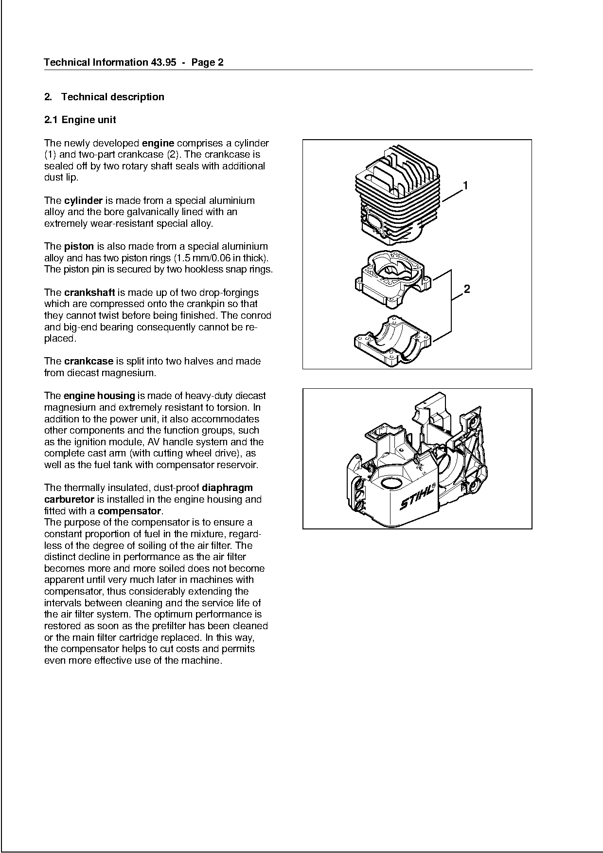
Text of page 2 — search, copy, screen readers
Technical Information 43.95 - Page 2

2. Technical description

2.1 Engine unit

The newly developed engine comprises a cylinder
(1) and two-part crankcase (2). The crankcase is
sealed off by two rotary shaft seals with additional
dust lip.
                                                                        1
The cylinder is made from a special aluminium
alloy and the bore galvanically lined with an
extremely wear-resistant special alloy.

The piston is also made from a special aluminium

alloy and has two piston rings (1.5 mm/0.06 in thick).
The piston pin is secured by two hookless snap rings.

The crankshaft is made up of two drop-forgings                             2
which are compressed onto the crankpin so that
they cannot twist before being finished. The conrod

and big-end bearing consequently cannot be re-
placed.

The crankcase is split into two halves and made
from diecast magnesium.
The engine housing is made of heavy-duty diecast
magnesium and extremely resistant to torsion. In

addition to the power unit, it also accommodates
other components and the function groups, such
as the ignition module, AV handle system and the
complete cast arm (with cutting wheel drive), as

well as the fuel tank with compensator reservoir.

The thermally insulated, dust-proof diaphragm
carburetor is installed in the engine housing and
fitted with a compensator.
The purpose of the compensator is to ensure a

constant proportion of fuel in the mixture, regard-
less of the degree of soiling of the air filter. The

distinct decline in performance as the air filter
becomes more and more soiled does not become
apparent until very much later in machines with
compensator, thus considerably extending the

intervals between cleaning and the service life of
the air filter system. The optimum performance is
restored as soon as the prefilter has been cleaned

or the main filter cartridge replaced. In this way,
the compensator helps to cut costs and permits
even more effective use of the machine.
Page 3 of 12
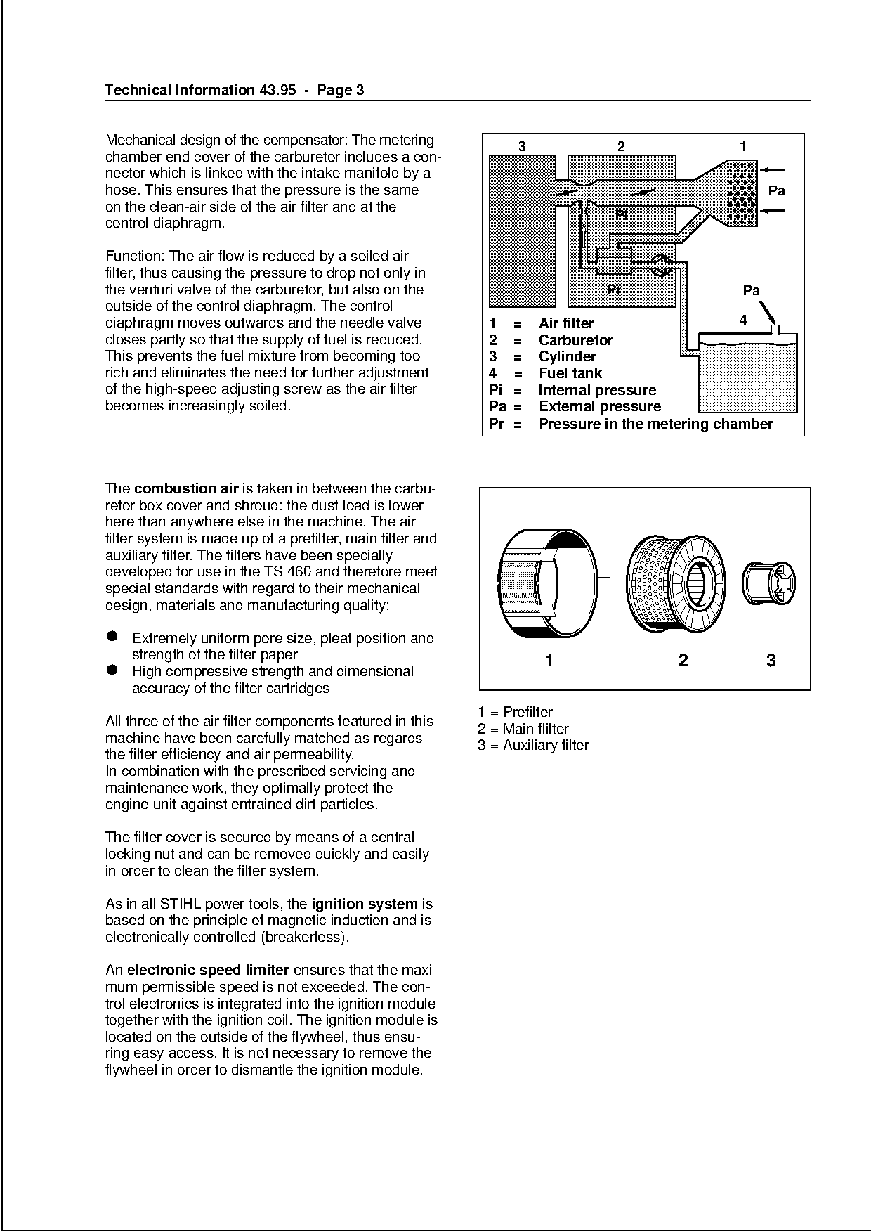
Text of page 3 — search, copy, screen readers
Technical Information 43.95 - Page 3

                                                                             ,

Mechanical design of the compensator: The metering                3                2              1
chamber end cover of the carburetor includes a con-
nector which is linked with the intake manifold by a
hose. This ensures that the pressure is the same                                                        Pa
on the clean-air side of the air filter and at the
                                                                                   Pi
control diaphragm.

Function: The air flow is reduced by a soiled air
filter, thus causing the pressure to drop not only in
the venturi valve of the carburetor, but also on the                              Pr               Pa
outside of the control diaphragm. The control
diaphragm moves outwards and the needle valve               11 == Luftfilter
                                                                      Air filter                    4
closes partly so that the supply of fuel is reduced.        22 == Vergaser
                                                                      Carburetor

This prevents the fuel mixture from becoming too            33 == Zylinder
                                                                      Cylinder

rich and eliminates the need for further adjustment         44 == Kraftstofftank
                                                                      Fuel tank
of the high-speed adjusting screw as the air filter         PiPi == Innendruck
                                                                      Internal pressure
becomes increasingly soiled.                                Pa
                                                             Pa== Außendruck
                                                                      External pressure

                                                             Pr == Druck
                                                                      Pressure   in the metering chamber
                                                                            im Regelraum

The combustion air is taken in between the carbu-
retor box cover and shroud: the dust load is lower
here than anywhere else in the machine. The air
filter system is made up of a prefilter, main filter and
auxiliary filter. The filters have been specially
developed for use in the TS 460 and therefore meet
special standards with regard to their mechanical

design, materials and manufacturing quality:

• strength
  Extremely uniform pore size, pleat position and
           of the filter paper
• accuracy of the filterstrength                                       1                 2              3

  High compressive                and dimensional
                           cartridges

                                                           1 = Prefilter
All three of the air filter components featured in this
                                                           2 = Main flilter
machine have been carefully matched as regards
                                                           3 = Auxiliary filter
the filter efficiency and air permeability.

In combination with the prescribed servicing and
maintenance work, they optimally protect the

engine unit against entrained dirt particles.

The filter cover is secured by means of a central
locking nut and can be removed quickly and easily

in order to clean the filter system.

As in all STIHL power tools, the ignition system is

based on the principle of magnetic induction and is
electronically controlled (breakerless).

An electronic speed limiter ensures that the maxi-
mum permissible speed is not exceeded. The con-
trol electronics is integrated into the ignition module
together with the ignition coil. The ignition module is
located on the outside of the flywheel, thus ensu-
ring easy access. It is not necessary to remove the
flywheel in order to dismantle the ignition module.
Page 4 of 12
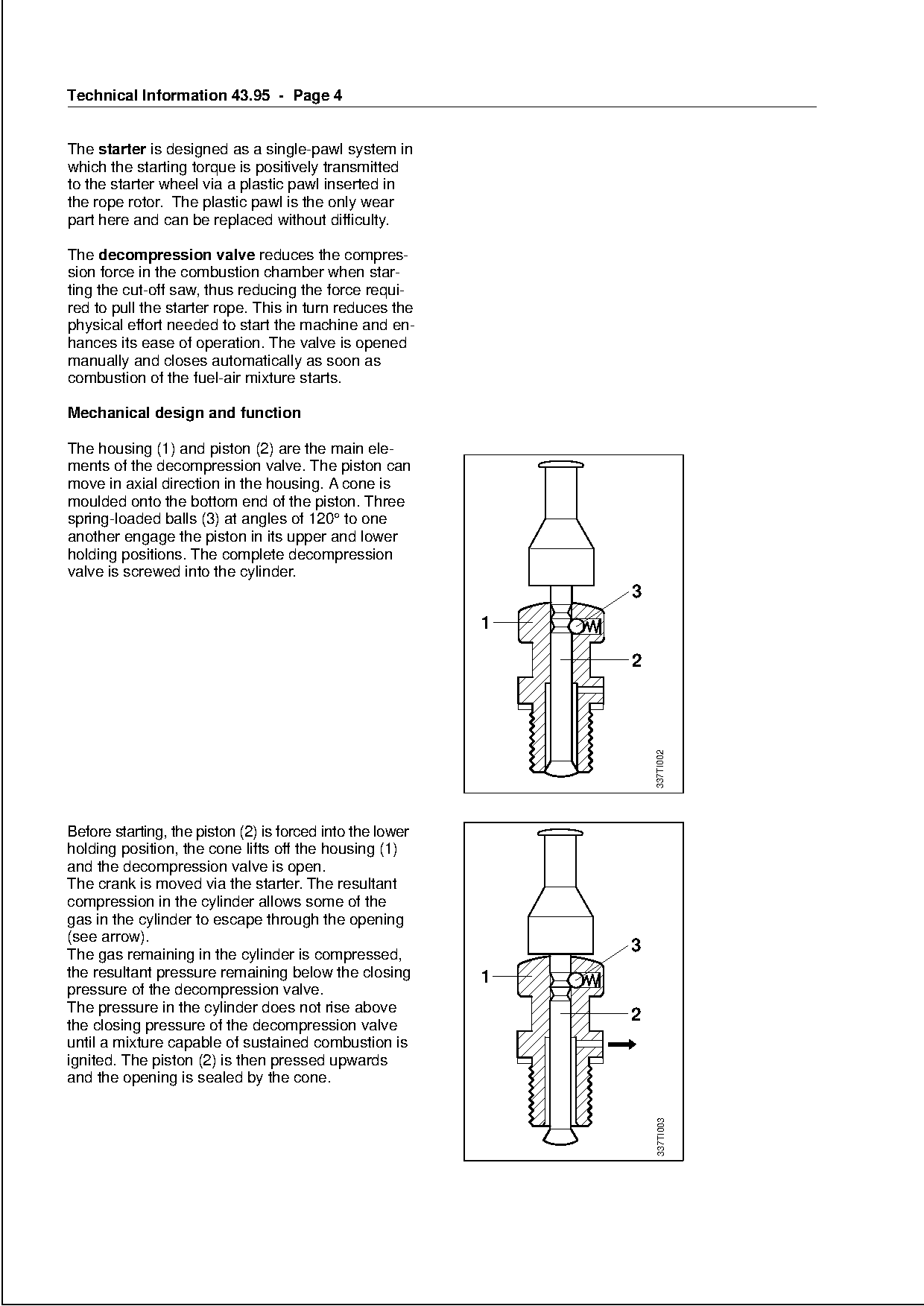
Text of page 4 — search, copy, screen readers
Technical Information 43.95 - Page 4

The starter is designed as a single-pawl system in
which the starting torque is positively transmitted
to the starter wheel via a plastic pawl inserted in
the rope rotor. The plastic pawl is the only wear
part here and can be replaced without difficulty.

The decompression valve reduces the compres-
sion force in the combustion chamber when star-
ting the cut-off saw, thus reducing the force requi-
red to pull the starter rope. This in turn reduces the
physical effort needed to start the machine and en-
hances its ease of operation. The valve is opened
manually and closes automatically as soon as

combustion of the fuel-air mixture starts.

Mechanical design and function

The housing (1) and piston (2) are the main ele-
ments of the decompression valve. The piston can
move in axial direction in the housing. A cone is

moulded onto the bottom end of the piston. Three
spring-loaded balls (3) at angles of 120° to one
another engage the piston in its upper and lower
holding positions. The complete decompression
valve is screwed into the cylinder.
                                                                      3


                                                                          337TI002

Before starting, the piston (2) is forced into the lower

holding position, the cone lifts off the housing (1)
and the decompression valve is open.
The crank is moved via the starter. The resultant
compression in the cylinder allows some of the

gas in the cylinder to escape through the opening
(see arrow).
The gas remaining in the cylinder is compressed,
                                                                      3

the resultant pressure remaining below the closing          1
pressure of the decompression valve.
The pressure in the cylinder does not rise above
                                                                      2
the closing pressure of the decompression valve
until a mixture capable of sustained combustion is
ignited. The piston (2) is then pressed upwards
and the opening is sealed by the cone.
                                                                          337TI003
Page 5 of 12
Text of page 5 — search, copy, screen readers
Technical Information 43.95 - Page 5

The cutting wheel drive with V-belt pulley, V-belt
and V-belt tensioner is integrated into the cast arm
and thus protected against dust.

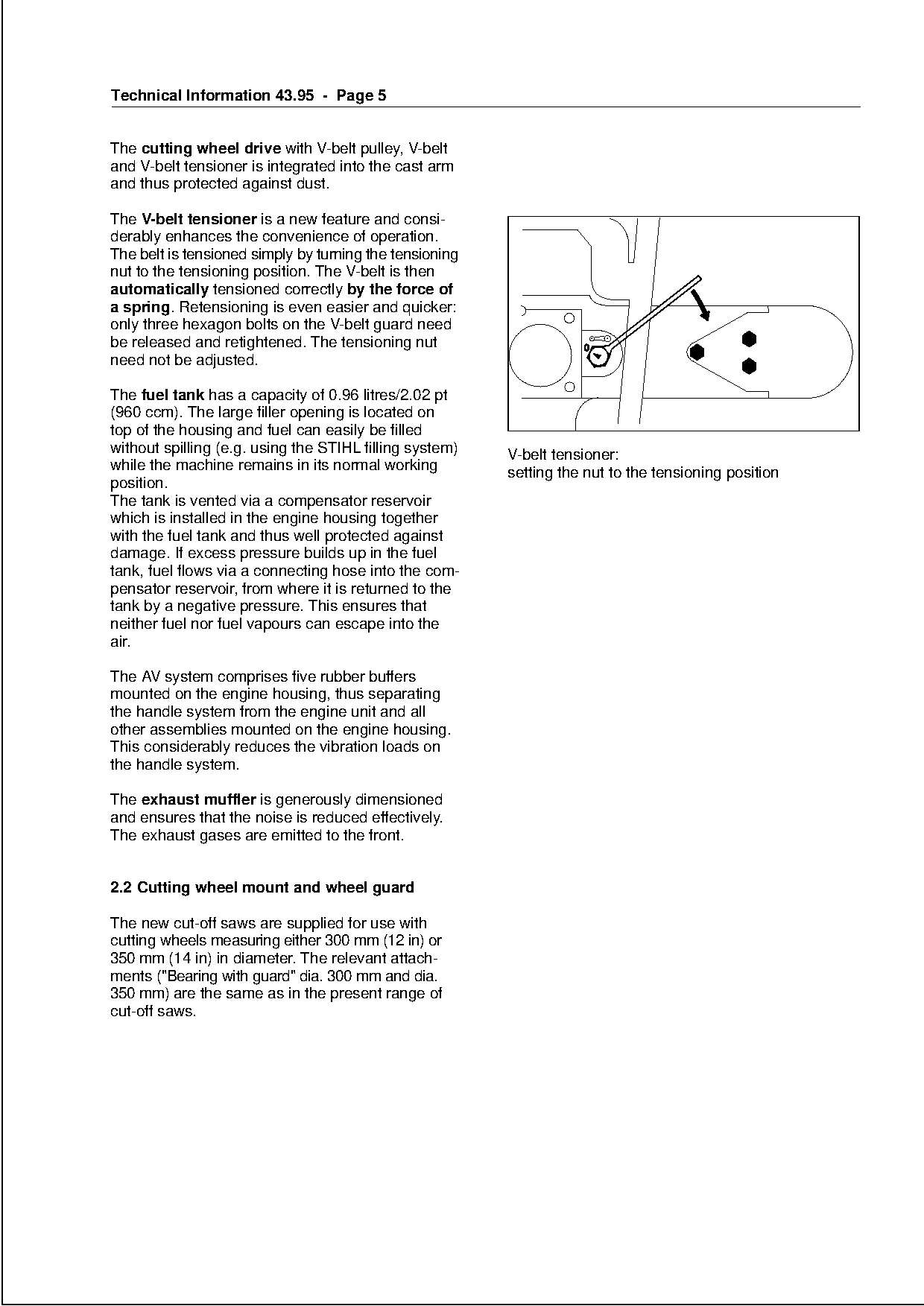
The V-belt tensioner is a new feature and consi-
derably enhances the convenience of operation.
The belt is tensioned simply by turning the tensioning
nut to the tensioning position. The V-belt is then
automatically tensioned correctly by the force of
a spring. Retensioning is even easier and quicker:
only three hexagon bolts on the V-belt guard need
be released and retightened. The tensioning nut
need not be adjusted.

The fuel tank has a capacity of 0.96 litres/2.02 pt
(960 ccm). The large filler opening is located on
top of the housing and fuel can easily be filled

without spilling (e.g. using the STIHL filling system)   V-belt tensioner:
while the machine remains in its normal working          setting the nut to the tensioning position
position.

The tank is vented via a compensator reservoir
which is installed in the engine housing together
with the fuel tank and thus well protected against
damage. If excess pressure builds up in the fuel
tank, fuel flows via a connecting hose into the com-
pensator reservoir, from where it is returned to the
tank by a negative pressure. This ensures that
neither fuel nor fuel vapours can escape into the

air.

The AV system comprises five rubber buffers
mounted on the engine housing, thus separating

the handle system from the engine unit and all
other assemblies mounted on the engine housing.

This considerably reduces the vibration loads on
the handle system.

The exhaust muffler is generously dimensioned

and ensures that the noise is reduced effectively.
The exhaust gases are emitted to the front.

2.2 Cutting wheel mount and wheel guard

The new cut-off saws are supplied for use with
cutting wheels measuring either 300 mm (12 in) or
350 mm (14 in) in diameter. The relevant attach-

ments ("Bearing with guard" dia. 300 mm and dia.
350 mm) are the same as in the present range of
cut-off saws.
Page 6 of 12
Text of page 6 — search, copy, screen readers
Technical Information 43.95 - Page 6

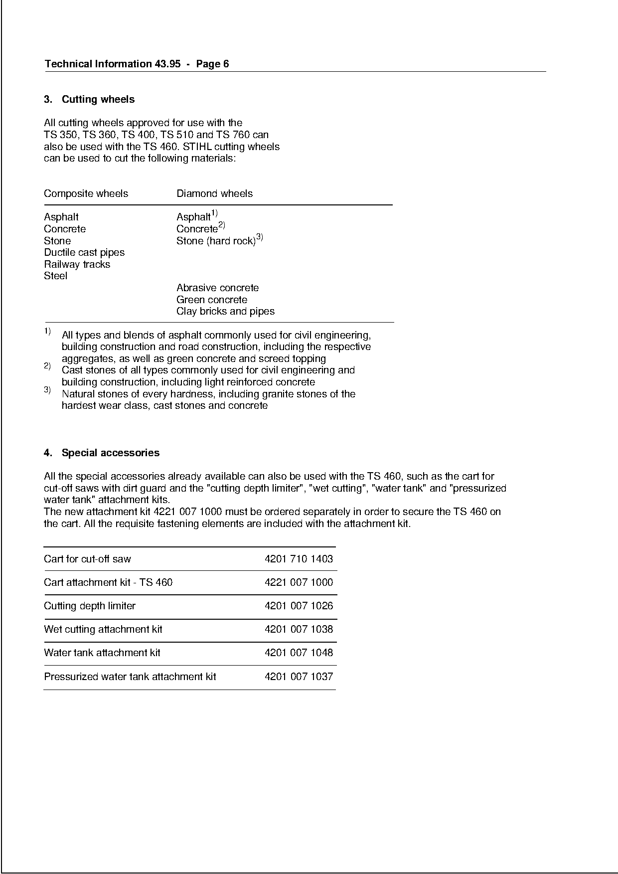
3. Cutting wheels

All cutting wheels approved for use with the
TS 350, TS 360, TS 400, TS 510 and TS 760 can
also be used with the TS 460. STIHL cutting wheels
can be used to cut the following materials:

Composite wheels               Diamond wheels

Asphalt                        Asphalt1)
Concrete                       Concrete2)
Stone                          Stone (hard rock)3)

Ductile cast pipes

Railway tracks
Steel
                               Abrasive concrete

                               Green concrete
                               Clay bricks and pipes

1)
   All types and blends of asphalt commonly used for civil engineering,
   building construction and road construction, including the respective
   aggregates, as well as green concrete and screed topping
2)
   Cast stones of all types commonly used for civil engineering and
   building construction, including light reinforced concrete
3)
   Natural stones of every hardness, including granite stones of the
   hardest wear class, cast stones and concrete

4. Special accessories

All the special accessories already available can also be used with the TS 460, such as the cart for
cut-off saws with dirt guard and the "cutting depth limiter", "wet cutting", "water tank" and "pressurized

water tank" attachment kits.
The new attachment kit 4221 007 1000 must be ordered separately in order to secure the TS 460 on
the cart. All the requisite fastening elements are included with the attachment kit.

Cart for cut-off saw                                 4201 710 1403

Cart attachment kit - TS 460                         4221 007 1000

Cutting depth limiter                                4201 007 1026

Wet cutting attachment kit                           4201 007 1038

Water tank attachment kit                            4201 007 1048

Pressurized water tank attachment kit                4201 007 1037
Page 7 of 12
Text of page 7 — search, copy, screen readers
Technical Information 43.95 - Page 7

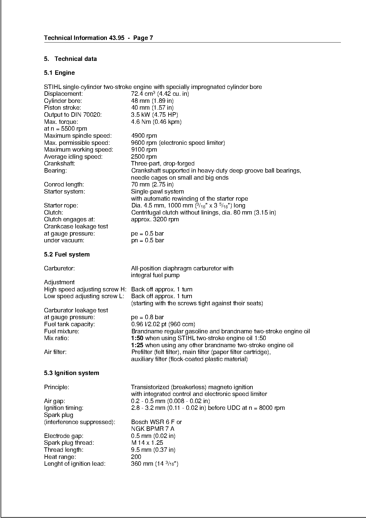
5. Technical data

5.1 Engine

STIHL single-cylinder two-stroke engine with specially impregnated cylinder bore
Displacement:                   72.4 cm3 (4.42 cu. in)
Cylinder bore:                  48 mm (1.89 in)
Piston stroke:                  40 mm (1.57 in)
Output to DIN 70020:            3.5 kW (4.75 HP)
Max. torque:                    4.6 Nm (0.46 kpm)
at n = 5500 rpm
Maximum spindle speed:          4900 rpm
Max. permissible speed:         9600 rpm (electronic speed limiter)

Maximum working speed:          9100 rpm

Average idling speed:           2500 rpm
Crankshaft:                     Three-part, drop-forged
Bearing:                        Crankshaft supported in heavy-duty deep groove ball bearings,

                                needle cages on small and big ends
Conrod length:                  70 mm (2.75 in)
Starter system:                 Single-pawl system

                                with automatic rewinding of the starter rope
Starter rope:                   Dia. 4.5 mm, 1000 mm (3/16" x 3 5/16") long
Clutch:                         Centrifugal clutch without linings, dia. 80 mm (3.15 in)
Clutch engages at:
Crankcase leakage test
                                approx. 3200 rpm          fo
at gauge pressure:              pe = 0.5 bar
under vacuum:                   pn = 0.5 bar

5.2 Fuel system

Carburetor:                    All-position diaphragm carburetor with
                               integral fuel pump

Adjustment
High speed adjusting screw H: Back off approx. 1 turn

Low speed adjusting screw L: Back off approx. 1 turn
                              (starting with the screws tight against their seats)
Carburator leakage test
at gauge pressure:            pe = 0.8 bar

Fuel tank capacity:           0.96 l/2.02 pt (960 ccm)
Fuel mixture:                 Brandname regular gasoline and brandname two-stroke engine oil

Mix ratio:                    1:50 when using STIHL two-stroke engine oil 1:50
                              1:25 when using any other brandname two-stroke engine oil
Air filter:                   Prefilter (felt filter), main filter (paper filter cartridge),
                              auxiliary filter (flock-coated plastic material)

5.3 Ignition system

Principle:                     Transistorized (breakerless) magneto ignition
                               with integrated control and electronic speed limiter
Air gap:                       0.2 - 0.5 mm (0.008 - 0.02 in)
Ignition timing:               2.8 - 3.2 mm (0.11 - 0.02 in) before UDC at n = 8000 rpm
Spark plug
(interference suppressed):     Bosch WSR 6 F or
                               NGK BPMR 7 A
Electrode gap:                 0.5 mm (0.02 in)
Spark plug thread:             M 14 x 1.25
Thread length:                 9.5 mm (0.37 in)
Heat range:                    200
Lenght of ignition lead:       360 mm (14 3/16")
Page 8 of 12
Text of page 8 — search, copy, screen readers
Technical Information 43.95 - Page 8

5.4 Weight

Machine without fuel,
complete with attachment
for cutting wheel, dia. 300 mm (12")
(without cutting wheel):         11.3 kg (24.9 lb)

5.5 Dimensions

Length with cutting wheel
(dia. 300 mm/12"):                750 mm (29.5 in)
Width with handle:                300 mm (12")

Height to handle:                 370 mm (14.5 in)

5.6 Accessories

Combination wrench
Locking pin

Screwdriver

6.   Special servicing tools                                   fo
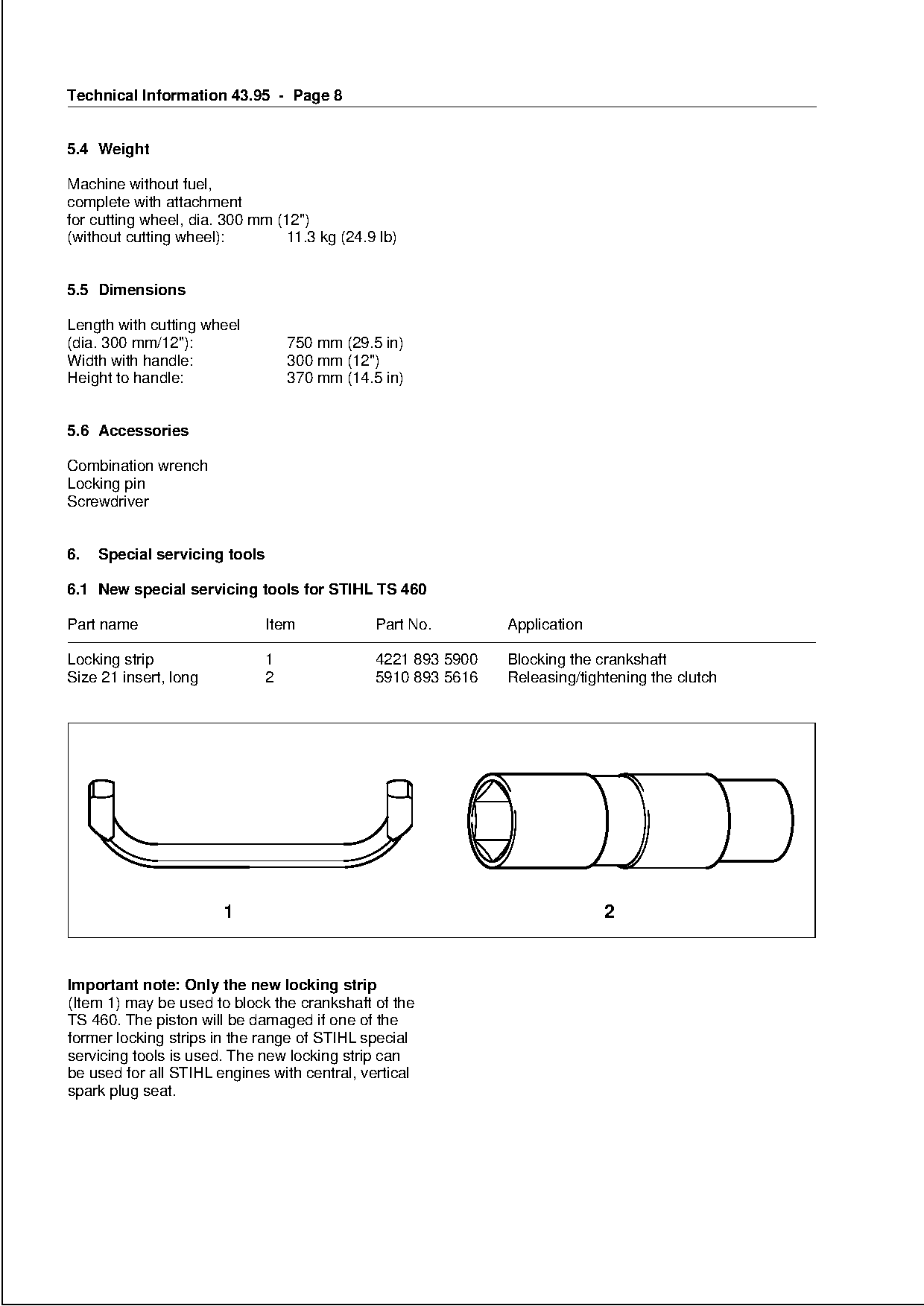
6.1 New special servicing tools for STIHL TS 460

Part name                      Item           Part No.        Application

Locking strip                 1               4221 893 5900   Blocking the crankshaft
Size 21 insert, long          2               5910 893 5616   Releasing/tightening the clutch

                       1                                                    2

Important note: Only the new locking strip
(Item 1) may be used to block the crankshaft of the
TS 460. The piston will be damaged if one of the
former locking strips in the range of STIHL special
servicing tools is used. The new locking strip can
be used for all STIHL engines with central, vertical
spark plug seat.
Page 9 of 12
Text of page 9 — search, copy, screen readers
Technical Information 43.95 - Page 9

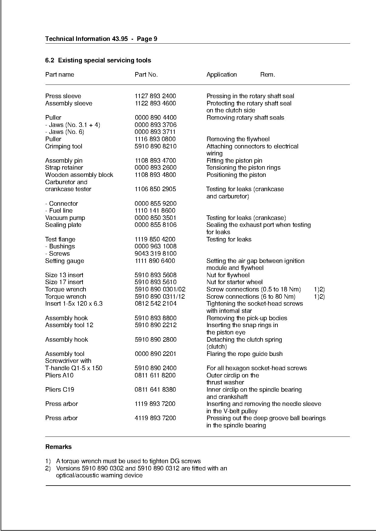
6.2 Existing special servicing tools

Part name                     Part No.                Application         Rem.

Press sleeve                  1127 893 2400           Pressing in the rotary shaft seal
Assembly sleeve               1122 893 4600           Protecting the rotary shaft seal
                                                      on the clutch side
Puller                        0000 890 4400           Removing rotary shaft seals
- Jaws (No. 3.1 + 4)          0000 893 3706
- Jaws (No. 6)                0000 893 3711
Puller                        1116 893 0800           Removing the flywheel
Crimping tool                 5910 890 8210           Attaching connectors to electrical

                                                      wiring

Assembly pin                  1108 893 4700           Fitting the piston pin
Strap retainer                0000 893 2600           Tensioning the piston rings
Wooden assembly block         1108 893 4800           Positioning the piston

Carburetor and
crankcase tester              1106 850 2905           Testing for leaks (crankcase
                                                      and carburetor)

- Connector                   0000 855 9200
- Fuel line                   1110 141 8600
Vacuum pump                   0000 850 3501           Testing for leaks (crankcase)
Sealing plate                 0000 855 8106             fo
                                                      Sealing the exhaust port when testing
                                                      for leaks
Test flange                   1119 850 4200           Testing for leaks
- Bushings                    0000 963 1008
- Screws                      9043 319 8100

Setting gauge                 1111 890 6400           Setting the air gap between ignition
                                                      module and flywheel
Size 13 insert                5910 893 5608           Nut for flywheel
Size 17 insert                5910 893 5610           Nut for starter wheel

Torque wrench                 5910 890 0301/02        Screw connections (0.5 to 18 Nm)        1)2)
Torque wrench                 5910 890 0311/12        Screw connections (6 to 80 Nm)          1)2)

Insert 1-5x 120 x 6.3         0812 542 2104           Tightening the socket-head screws
                                                      with internal star
Assembly hook                 5910 893 8800           Removing the pick-up bodies
Assembly tool 12              5910 890 2212           Inserting the snap rings in

                                                      the piston eye
Assembly hook                 5910 890 2800           Detaching the clutch spring

                                                      (clutch)
Assembly tool                 0000 890 2201           Flaring the rope guide bush
Screwdriver with
T-handle Q1-5 x 150           5910 890 2400           For all hexagon socket-head screws

Pliers A10                    0811 611 8200           Outer circlip on the
                                                      thrust washer
Pliers C19                    0811 641 8380           Inner circlip on the spindle bearing

                                                      and crankshaft
Press arbor                   1119 893 7200           Inserting and removing the needle sleeve
                                                      in the V-belt pulley
Press arbor                   4119 893 7200           Pressing out the deep groove ball bearings
                                                      in the spindle bearing

Remarks

1) A torque wrench must be used to tighten DG screws
2) Versions 5910 890 0302 and 5910 890 0312 are fitted with an
   optical/acoustic warning device
Page 10 of 12
Text of page 10 — search, copy, screen readers
Technical Information 43.95 - Page 10

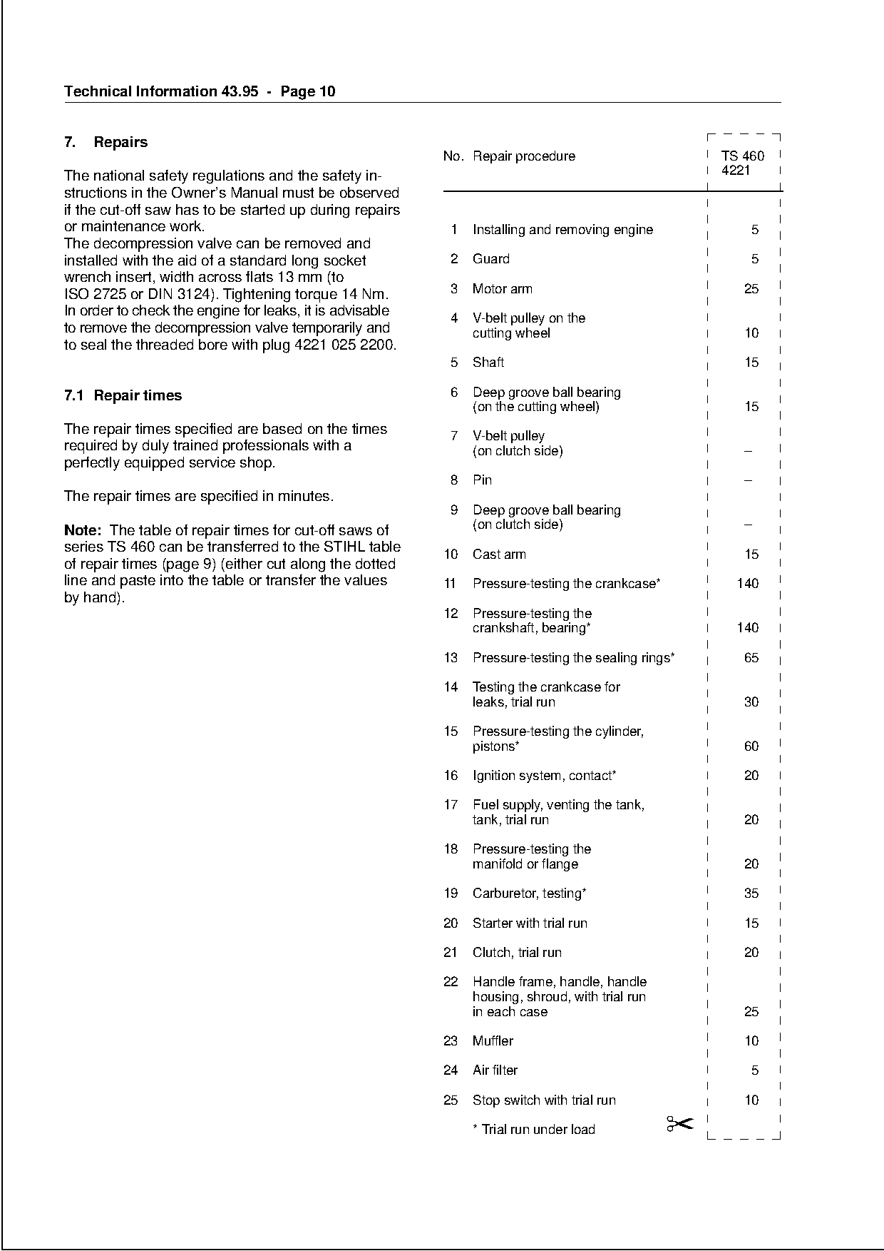
7.   Repairs
                                                          No. Repair procedure                       TS 460
The national safety regulations and the safety in-                                                   4221
structions in the Owner’s Manual must be observed
if the cut-off saw has to be started up during repairs
or maintenance work.                                       1   Installing and removing engine            5
The decompression valve can be removed and
installed with the aid of a standard long socket           2   Guard                                     5
wrench insert, width across flats 13 mm (to
ISO 2725 or DIN 3124). Tightening torque 14 Nm.            3   Motor arm                                25
In order to check the engine for leaks, it is advisable    4   V-belt pulley on the
to remove the decompression valve temporarily and              cutting wheel                            10
to seal the threaded bore with plug 4221 025 2200.

                                                           5   Shaft                                    15

7.1 Repair times                                           6   Deep groove ball bearing
                                                               (on the cutting wheel)                   15

The repair times specified are based on the times          7   V-belt pulley
required by duly trained professionals with a                  (on clutch side)                         –
perfectly equipped service shop.

                                                           8   Pin                                      –
The repair times are specified in minutes.
                                                           9   Deep groove ball bearing
Note: The table of repair times for cut-off saws of
series TS 460 can be transferred to the STIHL table
                                                               (on clutch side)                         –

                                                          10   Cast arm                                 15
of repair times (page 9) (either cut along the dotted
line and paste into the table or transfer the values      11   Pressure-testing the crankcase*         140
by hand).

                                                          12   Pressure-testing the
                                                               crankshaft, bearing*                    140

                                                          13   Pressure-testing the sealing rings*      65

                                                          14   Testing the crankcase for
                                                               leaks, trial run                         30

                                                          15   Pressure-testing the cylinder,
                                                               pistons*                                 60

                                                          16   Ignition system, contact*                20

                                                          17   Fuel supply, venting the tank,

                                                               tank, trial run                          20

                                                          18   Pressure-testing the
                                                               manifold or flange                       20

                                                          19   Carburetor, testing*                     35

                                                          20   Starter with trial run                   15

                                                          21   Clutch, trial run                        20

                                                          22   Handle frame, handle, handle
                                                               housing, shroud, with trial run
                                                               in each case                             25

                                                          23   Muffler                                  10

                                                          24   Air filter                                5

                                                          25   Stop switch with trial run               10

                                                               * Trial run under load            ✂
Page 11 of 12
Text of page 11 — search, copy, screen readers
Technical Information 43.95 - Page 11

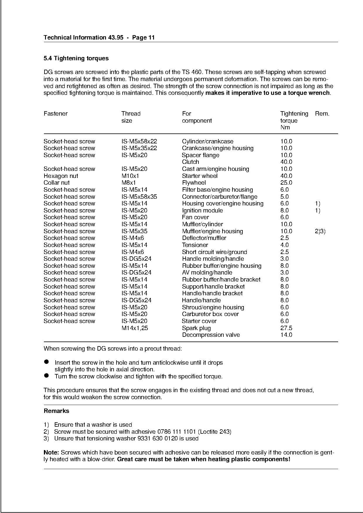
5.4 Tightening torques

DG screws are screwed into the plastic parts of the TS 460. These screws are self-tapping when screwed
into a material for the first time. The material undergoes permanent deformation. The screws can be remo-
ved and retightened as often as desired. The strength of the screw connection is not impaired as long as the
specified tightening torque is maintained. This consequently makes it imperative to use a torque wrench.

Fastener                     Thread                 For                                 Tightening    Rem.
                             size                   component                           torque
                                                                                        Nm

Socket-head screw            IS-M5x58x22            Cylinder/crankcase                  10.0

Socket-head screw            IS-M5x35x22            Crankcase/engine housing            10.0

Socket-head screw            IS-M5x20               Spacer flange                       10.0
                                                    Clutch                              40.0
Socket-head screw            IS-M5x20               Cast arm/engine housing             10.0

Hexagon nut                  M10x1                  Starter wheel                       40.0
Collar nut                   M8x1                   Flywheel                            25.0
Socket-head screw            IS-M5x14               Filter base/engine housing          6.0

Socket-head screw            IS-M5x58x35            Connector/carburetor/flange         5.0
Socket-head screw            IS-M5x14               Housing cover/engine housing        6.0           1)
Socket-head screw            IS-M5x20               Ignition module                     8.0           1)
Socket-head screw
Socket-head screw
                             IS-M5x20
                             IS-M5x14
                                                    Fan cover
                                                    Muffler/cylinder
                                                                                        6.0
                                                                                        10.0
Socket-head screw            IS-M5x35               Muffler/engine housing              10.0          2)3)
Socket-head screw            IS-M4x6                Deflector/muffler                   2.5
Socket-head screw            IS-M5x14               Tensioner                           4.0

Socket-head screw            IS-M4x6                Short circuit wire/ground           2.5
Socket-head screw            IS-DG5x24              Handle molding/handle               3.0
Socket-head screw            IS-M5x14               Rubber buffer/engine housing        8.0
Socket-head screw            IS-DG5x24              AV molding/handle                   3.0

Socket-head screw            IS-M5x14               Rubber buffer/handle bracket        8.0
Socket-head screw            IS-M5x14               Support/handle bracket              8.0

Socket-head screw            IS-M5x14               Handle/handle bracket               8.0
Socket-head screw            IS-DG5x24              Handle/handle                       8.0
Socket-head screw            IS-M5x20               Shroud/engine housing               6.0
Socket-head screw            IS-M5x20               Carburetor box cover                6.0

Socket-head screw            IS-M5x20               Starter cover                       6.0
                             M14x1,25               Spark plug                          27.5

                                                    Decompression valve                 14.0

When screwing the DG screws into a precut thread:

• slightly

  Insert the screw in the hole and turn anticlockwise until it drops
           into the hole in axial direction.
• Turn the screw clockwise and tighten with the specified torque.

This procedure ensures that the screw engages in the existing thread and does not cut a new thread,
for this would weaken the screw connection.

Remarks

1) Ensure that a washer is used
2) Screw must be secured with adhesive 0786 111 1101 (Loctite 243)
3) Unsure that tensioning washer 9331 630 0120 is used

Note: Screws which have been secured with adhesive can be released more easily if the connection is gent-
ly heated with a blow-drier. Great care must be taken when heating plastic components!
Page 12 of 12
Text of page 12 — search, copy, screen readers
Technical Information 43.95 - Page 12
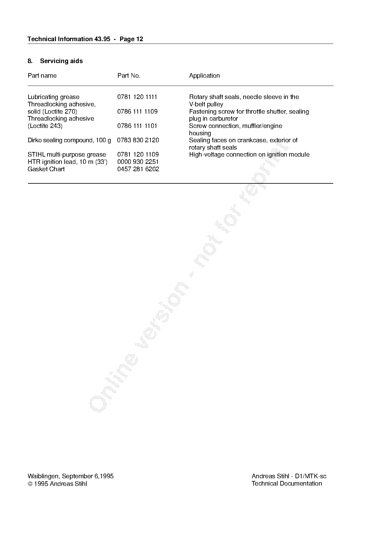
8. Servicing aids
Part name Part No. Application
Lubricating grease 0781 120 1111 Rotary shaft seals, needle sleeve in the
Threadlocking adhesive, V-belt pulley
solid (Loctite 270) 0786 111 1109 Fastening screw for throttle shutter, sealing
Threadlocking adhesive plug in carburetor
(Loctite 243) 0786 111 1101 Screw connection, muffler/engine
housing
Dirko sealing compound, 100 g 0783 830 2120 Sealing faces on crankcase, exterior of
rotary shaft seals
STIHL multi-purpose grease 0781 120 1109 High-voltage connection on ignition module
HTR ignition lead, 10 m (33’) 0000 930 2251
Gasket Chart 0457 281 6202
Waiblingen, September 6,1995 Andreas Stihl - D1/MTK-sc
1995 Andreas Stihl Technical Documentation Most of these PDFs embed fonts with a shifted character map, so the text above was recovered rather than copied — read it as a faithful but imperfect transcription, and treat the page image above each block as the authority where the two disagree — the figures exist only there, because they are vector drawings that text extraction cannot keep.