Technical Information · issue 46 of 1995
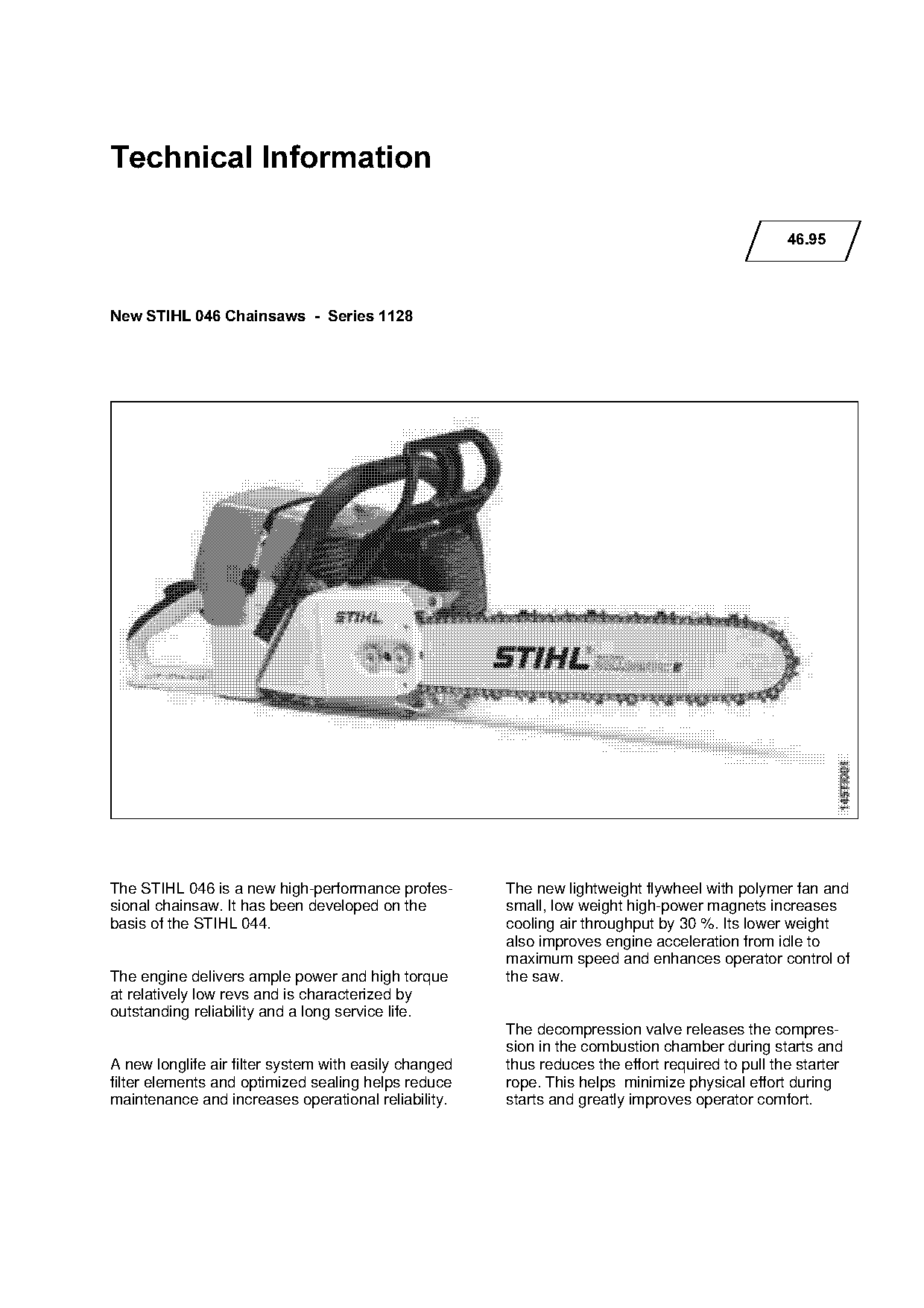
New chainsaw
IssueTI 46/1995
Engine family 1128
Full text
Page 1 of 12
Text of page 1 — search, copy, screen readers
Technical Information

                                                                                                  46.95

New STIHL 046 Chainsaws  -  Series 1128

The STIHL 046 is a new high-performance profes-        The new lightweight flywheel with polymer fan and
sional chainsaw. It has been developed on the          small, low weight high-power magnets increases

basis of the STIHL 044.                                cooling air throughput by 30 %. Its lower weight
                                                       also improves engine acceleration from idle to
                                                       maximum speed and enhances operator control of

The engine delivers ample power and high torque        the saw.
at relatively low revs and is characterized by
outstanding reliability and a long service life.
                                                       The decompression valve releases the compres-
                                                       sion in the combustion chamber during starts and
A new longlife air filter system with easily changed   thus reduces the effort required to pull the starter
filter elements and optimized sealing helps reduce     rope. This helps minimize physical effort during
maintenance and increases operational reliability.     starts and greatly improves operator comfort.
Page 2 of 12
Text of page 2 — search, copy, screen readers
Technical Information 46.95  -  Page 2

&RQWHQWV

1.    Technical Description
2.    Specifications
3.    Special Accessories for User
4.    Service Accessories
5.    Repairs
6.    Spare Parts

1.=Technical Description

Comparisons made in this chapter describe the

differences between the STIHL 046 and STIHL

044.

1.1=====Air Filter System

The new air filter system is characterized by
excellent filtering efficiency, long periods between

cleanings and ease of maintenance. Cleaning is
necessary only when there is a noticeable drop in
engine power. No tools are required to remove the
filter element.
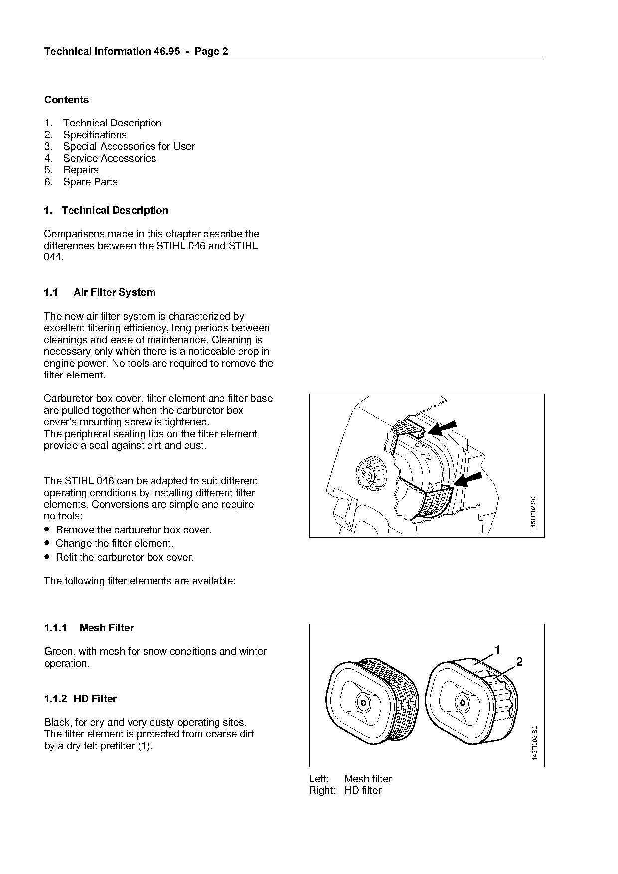
Carburetor box cover, filter element and filter base
are pulled together when the carburetor box
cover’s mounting screw is tightened.

The peripheral sealing lips on the filter element
provide a seal against dirt and dust.

The STIHL 046 can be adapted to suit different

operating conditions by installing different filter

                                                                                              145TI002 SC
elements. Conversions are simple and require
no tools:
• Remove the carburetor box cover.

• Change the filter element.
• Refit the carburetor box cover.

The following filter elements are available:

1.1.1====Mesh Filter

Green, with mesh for snow conditions and winter                                       1
operation.                                                                                2

1.1.2=HD Filter

Black, for dry and very dusty operating sites.
                                                                                                145TI003 SC

The filter element is protected from coarse dirt
by a dry felt prefilter (1).

                                                           Left: Mesh filter
                                                           Right: HD filter
Page 3 of 12
Text of page 3 — search, copy, screen readers
Technical Information 46.95  -  Page 3

The fabric of the HD filter element (2) must be
impregnated with STIHL HD filter oil before it is
used for the first time. Filter efficiency is severely
impaired in the dry condition. The saw comes with a
100 ml (3.5 fl.oz) bottle of filter oil.

In order to avoid the risk of icing up, the HD filter
should be replaced by a mesh filter in winter
operating conditions.

1.2====Compensator

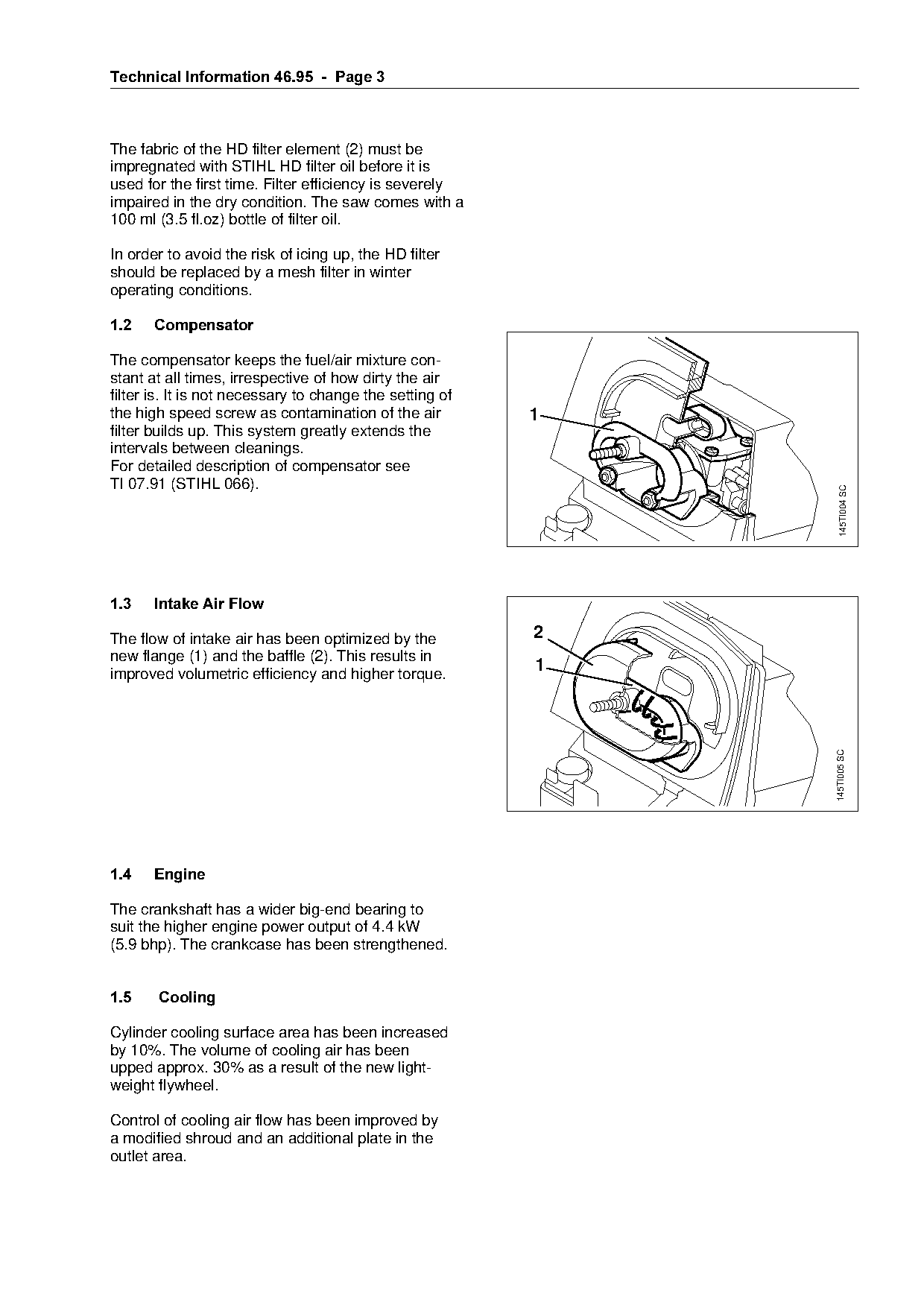
The compensator keeps the fuel/air mixture con-

stant at all times, irrespective of how dirty the air

filter is. It is not necessary to change the setting of
the high speed screw as contamination of the air           1
filter builds up. This system greatly extends the

intervals between cleanings.
For detailed description of compensator see
TI 07.91 (STIHL 066).

                                                                          145TI004 SC
1.3====Intake Air Flow

The flow of intake air has been optimized by the           2

new flange (1) and the baffle (2). This results in
improved volumetric efficiency and higher torque.
                                                           1

                                                                        145TI005 SC

1.4====Engine

The crankshaft has a wider big-end bearing to
suit the higher engine power output of 4.4 kW
(5.9 bhp). The crankcase has been strengthened.

1.5==== Cooling

Cylinder cooling surface area has been increased
by 10%. The volume of cooling air has been
upped approx. 30% as a result of the new light-
weight flywheel.

Control of cooling air flow has been improved by
a modified shroud and an additional plate in the
outlet area.
Page 4 of 12
Text of page 4 — search, copy, screen readers
Technical Information 46.95  -  Page 4

1.6=Decompression Valve

1.6.1= Construction
                                                                   3
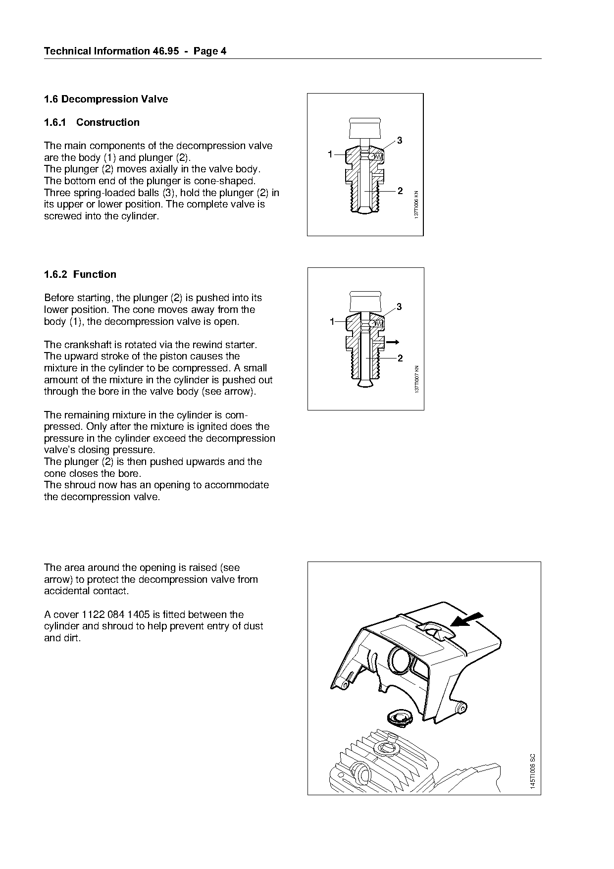
The main components of the decompression valve
are the body (1) and plunger (2).                         1
The plunger (2) moves axially in the valve body.
The bottom end of the plunger is cone-shaped.
Three spring-loaded balls (3), hold the plunger (2) in             2

                                                                       137TI006 KN
its upper or lower position. The complete valve is
screwed into the cylinder.

1.6.2=Function

Before starting, the plunger (2) is pushed into its
lower position. The cone moves away from the                       3
body (1), the decompression valve is open.                1

The crankshaft is rotated via the rewind starter.
The upward stroke of the piston causes the                         2
mixture in the cylinder to be compressed. A small             fo
                                                                        137TI007 KN
amount of the mixture in the cylinder is pushed out
through the bore in the valve body (see arrow).

The remaining mixture in the cylinder is com-

pressed. Only after the mixture is ignited does the
pressure in the cylinder exceed the decompression
valve’s closing pressure.
The plunger (2) is then pushed upwards and the

cone closes the bore.
The shroud now has an opening to accommodate

the decompression valve.

The area around the opening is raised (see
arrow) to protect the decompression valve from
accidental contact.

A cover 1122 084 1405 is fitted between the
cylinder and shroud to help prevent entry of dust
and dirt.

                                                                                      145TI006 SC
Page 5 of 12
Text of page 5 — search, copy, screen readers
Technical Information 46.95  -  Page 5

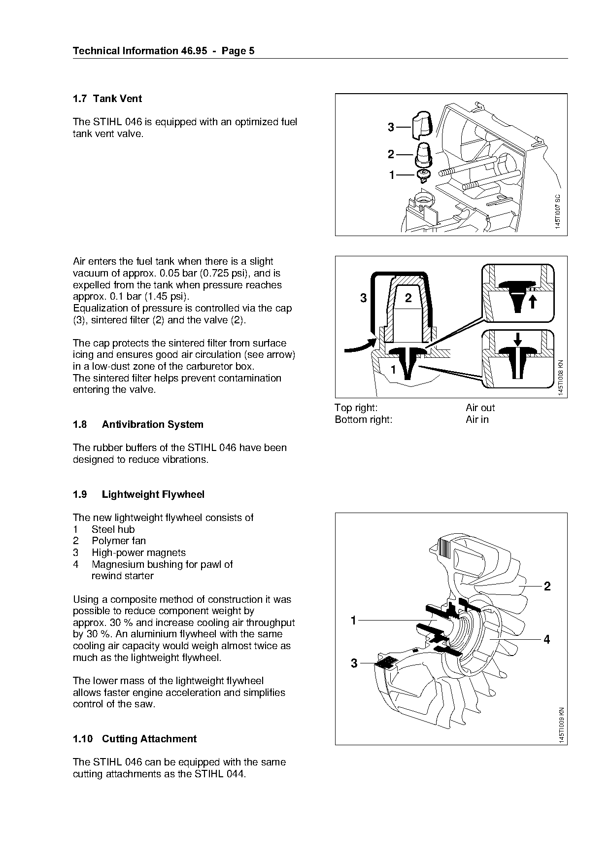
1.7= Tank Vent

The STIHL 046 is equipped with an optimized fuel
tank vent valve.
                                                                3

                                                                2
                                                                 1

                                                                                       145TI007 SC
Air enters the fuel tank when there is a slight
vacuum of approx. 0.05 bar (0.725 psi), and is
expelled from the tank when pressure reaches

approx. 0.1 bar (1.45 psi).                                 3        2
Equalization of pressure is controlled via the cap
(3), sintered filter (2) and the valve (2).

The cap protects the sintered filter from surface
icing and ensures good air circulation (see arrow)

                                                                                             145TI008 KN
in a low-dust zone of the carburetor box.                        1
The sintered filter helps prevent contamination
entering the valve.
                                                     Top right:          Air out
                                                     Bottom right:       Air in
1.8===Antivibration System

The rubber buffers of the STIHL 046 have been
designed to reduce vibrations.

1.9===Lightweight Flywheel

The new lightweight flywheel consists of
1 Steel hub

2 Polymer fan
3 High-power magnets

4 Magnesium bushing for pawl of
   rewind starter
                                                                                   2
Using a composite method of construction it was

possible to reduce component weight by
approx. 30 % and increase cooling air throughput        1
by 30 %. An aluminium flywheel with the same

cooling air capacity would weigh almost twice as
                                                                                   4
much as the lightweight flywheel.
                                                        3
The lower mass of the lightweight flywheel
allows faster engine acceleration and simplifies
control of the saw.
                                                                                              145TI009 KN

1.10=Cutting Attachment

The STIHL 046 can be equipped with the same
cutting attachments as the STIHL 044.
Page 6 of 12
Text of page 6 — search, copy, screen readers
Technical Information 46.95  -  Page 6

1.11=Crankcase/Cylinder Assembly

This assembly uses 6 mm mounting screws and a
sheet steel cylinder gasket.
See also service note.

2.=====Specifications
2.1====Engine

STIHL single-cylinder two-stroke engine with special impregnated cylinder bore

Displacement:                      76.5 cm3 (4.67 cu.in)
Bore:                              52 mm (2.05 in)
Stroke:                            36 mm (1.42 in)

Compression ratio:                 9.6 : 1
Engine power:                      4.4 kW (5.9 bhp) at 9,500 rpm
Max. torque:                       4.8 Nm (3.54 lb.ft) at 6,500 rpm

Max. permissible engine speed
with Rollomatic bar and chain      13,500 rpm
Mean idle speed:                   2,500 rpm
Crankshaft:
Main bearings:
                                   Three-part, drop forged
                                   Two deep-groove ball bearings
Big end bearing:                   Needle cage
Connecting rod length:       62 mm (2.44 in)
Piston pin diameter:               12 mm (0.47 in)

Small end bearing:                 Needle cage
Clutch:                            Centrifugal clutch without linings
Diameter:                          76 mm (3.0 in)
Clutch engages at:                 approx. 3,500 rpm

Rewind starter:                    Pawl engagement with automatic starter rope rewind mechanism,
                                   ElastoStart

Starter rope diameter:       3.5 mm (0.14 in)

2.2====Fuel System

Carburetor:                      All position diaphragm carburetor with integral fuel pump
Standard setting;

- High speed screw H:            Open 1 turn
- Low speed screw L:             Open 1 turn
Fuel tank capacity:              0.94 l (2 US pt)
Fuel mixture:                    Regular brand-name gasoline and two-stroke engine oil

Octane number:                   min. pump octane 89 unleaded
Mix ratio:                       50:1 with STIHL 50:1 two-stroke engine oil
                                 25:1 with other brand-name two-stroke, air-cooled engine oils

Compensator:                     Allows constant pressure at clean air side of air filter and metering
                                 diaphraghm, irrespective of degree of filter contamination
Air filters
- Mesh filter                    Wire mesh for winter operation
- HD filter                      For dry, very dusty operating sites

2.3====Ignition System

Type:                            Electronic magneto ignition (breakerless)
Flywheel:                        Lightweight polymer flywheel with steel hub and
                                 magnesium bushing for pawl engagement
Air gap:                         0.15 - 0.30 mm (0.006-0.012 in)
Ignition timing:                 2.0 - 3.0 mm (0.080-0.12 in) B.T.D.C.
Page 7 of 12

Text of page 7 — search, copy, screen readers
Technical Information 46.95  -  Page 7

Spark plug (suppressed):           Bosch WSR 6 F
Electrode gap:                     0.5 mm (0.020 in)
Spark plug thread:                 M14 x 1.25
Length of thread:                  9.5 mm (0.37 in)
Heat range:                        200

2.4===Weights

Powerhead without cutting
attachment:                        6.5 kg (14.3 lb)
Power to weight ratio              2.55 lbs/bhp

3.====Special Accessories for User

STIHL repair kit 046                 1128 900 5001
3/8", 7-tooth rim sprocket kit*1128 007 1000
3/8", 8-tooth rim sprocket kit 1128 007 1001

3/8", 7-tooth spur sprocket* 1128 640 2000
3/8", 8-tooth spur sprocket 1128 640 2005
Chain scabbard extension 0000 792 9132

*) Part may be standard equipment in some
markets

4.====Service Accessories

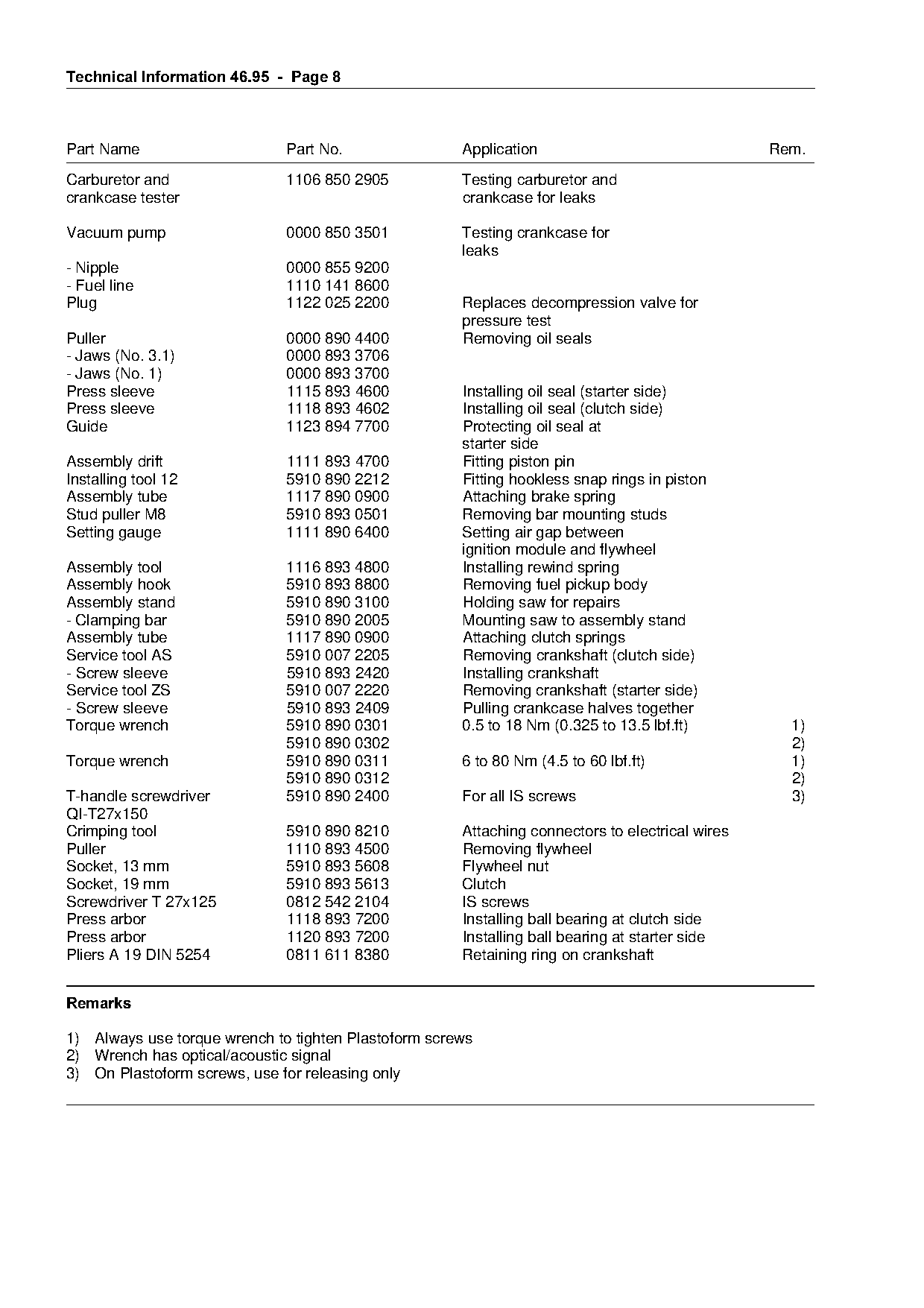
4.1===Special Servicing Tools

Part Name                       Part No.               Application                Rem.

Locking strip                   0000 893 5903          Blocking the crankshaft
Sealing plate                   0000 855 8106          Sealing exhaust port for

                                                       leakage test
Wooden assembly block           1108 893 4800          Fitting piston
Clamping strap                  0000 893 2600          Compressing piston rings

Test flange                     1128 850 4200          Leakage test
- Sleeves                       0000 963 1008
Page 8 of 12
Text of page 8 — search, copy, screen readers
Technical Information 46.95  -  Page 8

Part Name                     Part No.                Application                                Rem.
Carburetor and                1106 850 2905           Testing carburetor and
crankcase tester                                      crankcase for leaks

Vacuum pump                   0000 850 3501           Testing crankcase for
                                                      leaks
- Nipple                      0000 855 9200
- Fuel line                   1110 141 8600
Plug                          1122 025 2200           Replaces decompression valve for
                                                      pressure test
Puller                        0000 890 4400           Removing oil seals
- Jaws (No. 3.1)              0000 893 3706

- Jaws (No. 1)                0000 893 3700

Press sleeve                  1115 893 4600           Installing oil seal (starter side)
Press sleeve                  1118 893 4602           Installing oil seal (clutch side)
Guide                         1123 894 7700           Protecting oil seal at

                                                      starter side
Assembly drift                1111 893 4700           Fitting piston pin
Installing tool 12            5910 890 2212           Fitting hookless snap rings in piston

Assembly tube                 1117 890 0900           Attaching brake spring
Stud puller M8                5910 893 0501           Removing bar mounting studs
Setting gauge                 1111 890 6400           Setting air gap between

Assembly tool                 1116 893 4800
                                                      ignition module and flywheel
                                                      Installing rewind spring
Assembly hook                 5910 893 8800           Removing fuel pickup body
Assembly stand                5910 890 3100           Holding saw for repairs
- Clamping bar                5910 890 2005           Mounting saw to assembly stand
Assembly tube                 1117 890 0900           Attaching clutch springs

Service tool AS               5910 007 2205           Removing crankshaft (clutch side)
- Screw sleeve                5910 893 2420           Installing crankshaft
Service tool ZS               5910 007 2220           Removing crankshaft (starter side)

- Screw sleeve                5910 893 2409           Pulling crankcase halves together
Torque wrench                 5910 890 0301           0.5 to 18 Nm (0.325 to 13.5 lbf.ft)          1)

                              5910 890 0302                                                        2)
Torque wrench                 5910 890 0311           6 to 80 Nm (4.5 to 60 lbf.ft)                1)
                              5910 890 0312                                                        2)
T-handle screwdriver          5910 890 2400           For all IS screws                            3)

QI-T27x150
Crimping tool                 5910 890 8210           Attaching connectors to electrical wires

Puller                        1110 893 4500           Removing flywheel
Socket, 13 mm                 5910 893 5608           Flywheel nut
Socket, 19 mm                 5910 893 5613           Clutch
Screwdriver T 27x125          0812 542 2104           IS screws

Press arbor                   1118 893 7200           Installing ball bearing at clutch side
Press arbor                   1120 893 7200           Installing ball bearing at starter side
Pliers A 19 DIN 5254          0811 611 8380           Retaining ring on crankshaft

5HPDUNV

1) Always use torque wrench to tighten Plastoform screws
2) Wrench has optical/acoustic signal
3) On Plastoform screws, use for releasing only
Page 9 of 12
Text of page 9 — search, copy, screen readers
Technical Information 46.95  -  Page

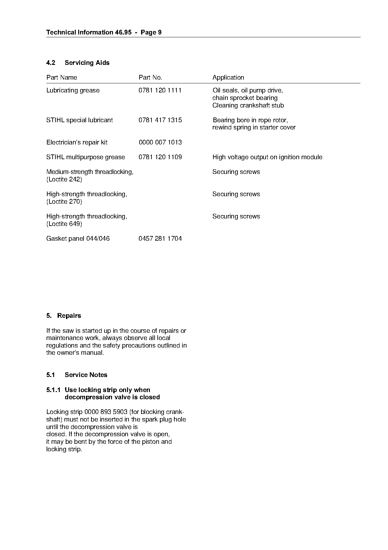
4.2====Servicing Aids

Part Name                         Part No.             Application

Lubricating grease                0781 120 1111        Oil seals, oil pump drive,
                                                       chain sprocket bearing
                                                       Cleaning crankshaft stub

STIHL special lubricant           0781 417 1315        Bearing bore in rope rotor,
                                                       rewind spring in starter cover

Electrician’s repair kit          0000 007 1013

STIHL multipurpose grease         0781 120 1109        High voltage output on ignition module

Medium-strength threadlocking,                         Securing screws
(Loctite 242)

High-strength threadlocking,                           Securing screws
(Loctite 270)

High-strength threadlocking,                           Securing screws
(Loctite 649)

Gasket panel 044/046              0457 281 1704

5.=Repairs

If the saw is started up in the course of repairs or

maintenance work, always observe all local
regulations and the safety precautions outlined in
the owner’s manual.

5.1====Service Notes

5.1.1=Use locking strip only when
======decompression valve is closed

Locking strip 0000 893 5903 (for blocking crank-
shaft) must not be inserted in the spark plug hole
until the decompression valve is
closed. If the decompression valve is open,
it may be bent by the force of the piston and
locking strip.
Page 10 of 12
Text of page 10 — search, copy, screen readers
Technical Information 46.95  -  Page 10

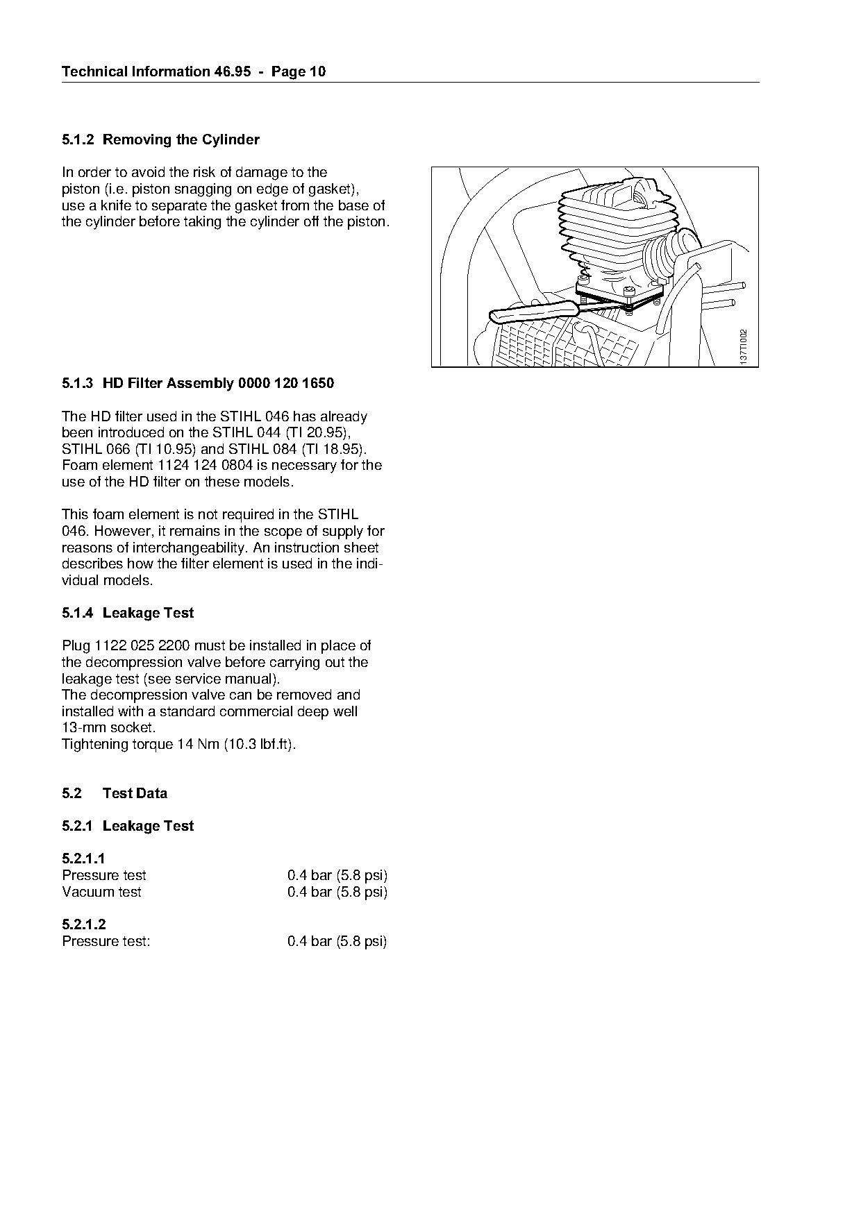
5.1.2=Removing the Cylinder

In order to avoid the risk of damage to the
piston (i.e. piston snagging on edge of gasket),
use a knife to separate the gasket from the base of
the cylinder before taking the cylinder off the piston.

                                                                            137TI002
5.1.3=HD Filter Assembly 0000 120 1650

The HD filter used in the STIHL 046 has already
been introduced on the STIHL 044 (TI 20.95),
STIHL 066 (TI 10.95) and STIHL 084 (TI 18.95).

Foam element 1124 124 0804 is necessary for the
use of the HD filter on these models.

This foam element is not required in the STIHL
046. However, it remains in the scope of supply for
reasons of interchangeability. An instruction sheet
describes how the filter element is used in the indi-
vidual models.

5.1.4=Leakage Test

Plug 1122 025 2200 must be installed in place of

the decompression valve before carrying out the
leakage test (see service manual).

The decompression valve can be removed and
installed with a standard commercial deep well
13-mm socket.
Tightening torque 14 Nm (10.3 lbf.ft).

5.2===Test Data

5.2.1=Leakage Test

5.2.1.1
Pressure test                        0.4 bar (5.8 psi)
Vacuum test                          0.4 bar (5.8 psi)

5.2.1.2
Pressure test:                       0.4 bar (5.8 psi)
Page 11 of 12
Text of page 11 — search, copy, screen readers
Technical Information 46.95  -  Page 11

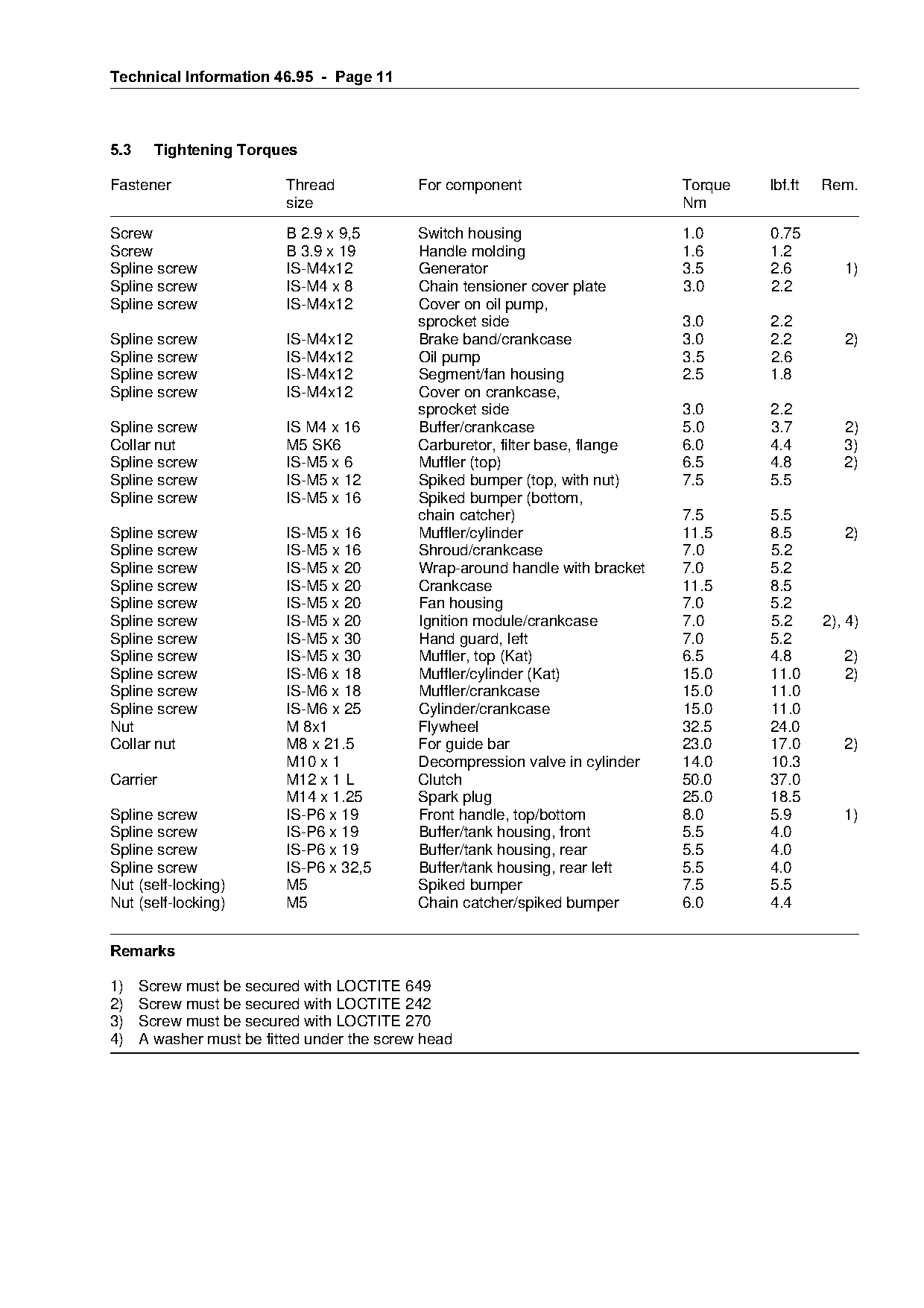
5.3=====Tightening Torques

Fastener                  Thread             For component                     Torque   lbf.ft   Rem.
                          size                                                 Nm
Screw                     B 2.9 x 9,5        Switch housing                    1.0      0.75
Screw                     B 3.9 x 19         Handle molding                    1.6      1.2
Spline screw              IS-M4x12           Generator                         3.5      2.6         1)
Spline screw              IS-M4 x 8          Chain tensioner cover plate       3.0      2.2
Spline screw              IS-M4x12           Cover on oil pump,
                                             sprocket side                     3.0      2.2
Spline screw              IS-M4x12           Brake band/crankcase              3.0      2.2         2)
Spline screw              IS-M4x12           Oil pump                          3.5      2.6

Spline screw              IS-M4x12           Segment/fan housing               2.5      1.8

Spline screw              IS-M4x12           Cover on crankcase,
                                             sprocket side                     3.0      2.2
Spline screw              IS M4 x 16         Buffer/crankcase                  5.0      3.7         2)

Collar nut                M5 SK6             Carburetor, filter base, flange   6.0      4.4         3)
Spline screw              IS-M5 x 6          Muffler (top)                     6.5      4.8         2)
Spline screw              IS-M5 x 12         Spiked bumper (top, with nut)     7.5      5.5

Spline screw              IS-M5 x 16         Spiked bumper (bottom,
                                             chain catcher)                    7.5      5.5
Spline screw              IS-M5 x 16         Muffler/cylinder                  11.5     8.5         2)
Spline screw
Spline screw
                          IS-M5 x 16
                          IS-M5 x 20
                                             Shroud/crankcase
                                             Wrap-around handle with bracket
                                                                               7.0
                                                                               7.0
                                                                                        5.2
                                                                                        5.2
Spline screw              IS-M5 x 20         Crankcase                         11.5     8.5
Spline screw              IS-M5 x 20         Fan housing                       7.0      5.2
Spline screw              IS-M5 x 20         Ignition module/crankcase         7.0      5.2      2), 4)
Spline screw              IS-M5 x 30         Hand guard, left                  7.0      5.2

Spline screw              IS-M5 x 30         Muffler, top (Kat)                6.5      4.8         2)
Spline screw              IS-M6 x 18         Muffler/cylinder (Kat)            15.0     11.0        2)
Spline screw              IS-M6 x 18         Muffler/crankcase                 15.0     11.0

Spline screw              IS-M6 x 25         Cylinder/crankcase                15.0     11.0
Nut                       M 8x1              Flywheel                          32.5     24.0

Collar nut                M8 x 21.5          For guide bar                     23.0     17.0        2)
                          M10 x 1            Decompression valve in cylinder   14.0     10.3
Carrier                   M12 x 1 L          Clutch                            50.0     37.0
                          M14 x 1.25         Spark plug                        25.0     18.5

Spline screw              IS-P6 x 19         Front handle, top/bottom          8.0      5.9         1)
Spline screw              IS-P6 x 19         Buffer/tank housing, front        5.5      4.0

Spline screw              IS-P6 x 19         Buffer/tank housing, rear         5.5      4.0
Spline screw              IS-P6 x 32,5       Buffer/tank housing, rear left    5.5      4.0
Nut (self-locking)        M5                 Spiked bumper                     7.5      5.5
Nut (self-locking)        M5                 Chain catcher/spiked bumper       6.0      4.4

5HPDUNV

1)    Screw must be secured with LOCTITE 649
2)    Screw must be secured with LOCTITE 242
3)    Screw must be secured with LOCTITE 270
4)    A washer must be fitted under the screw head
Page 12 of 12
Text of page 12 — search, copy, screen readers
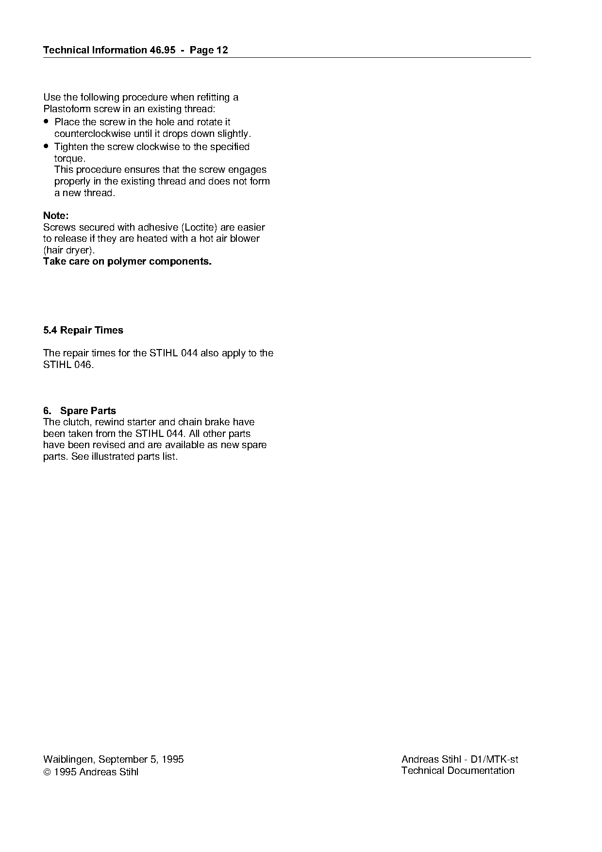
Technical Information 46.95 - Page 12 Use the following procedure when refitting a Plastoform screw in an existing thread: • Place the screw in the hole and rotate it counterclockwise until it drops down slightly. • Tighten the screw clockwise to the specified torque. This procedure ensures that the screw engages properly in the existing thread and does not form a new thread. 1RWH Screws secured with adhesive (Loctite) are easier to release if they are heated with a hot air blower (hair dryer). Take care on polymer components. 5.4=Repair Times The repair times for the STIHL 044 also apply to the STIHL 046. 6.=Spare Parts The clutch, rewind starter and chain brake have been taken from the STIHL 044. All other parts have been revised and are available as new spare parts. See illustrated parts list. Waiblingen, September 5, 1995 Andreas Stihl - D1/MTK-st 1995 Andreas Stihl Technical Documentation
Most of these PDFs embed fonts with a shifted character map, so the text above was recovered rather than copied — read it as a faithful but imperfect transcription, and treat the page image above each block as the authority where the two disagree — the figures exist only there, because they are vector drawings that text extraction cannot keep.