Technical Information · issue 49 of 1995
Easy start system; rope rotor; HS 276 A carburetor
IssueTI 49/1995
From serial 3 214 427, 32 144 279
Part changes (3)
| Was | Becomes | What the bulletin says |
|---|---|---|
| 4221 195 0400 | 4221 190 1000 | The rope rotor 4221 195 0400 will be replaced by version 4221 190 1000 (with pressed-in bushing) in the foreseeable future, in order further to improve the machine’s functioning. |
| 4221 400 1305 | 4223 400 1300 | Ignition module 4221 400 1305 will be replaced by version 4223 400 1300 in the foreseeable future in order to promote the standardization of parts. |
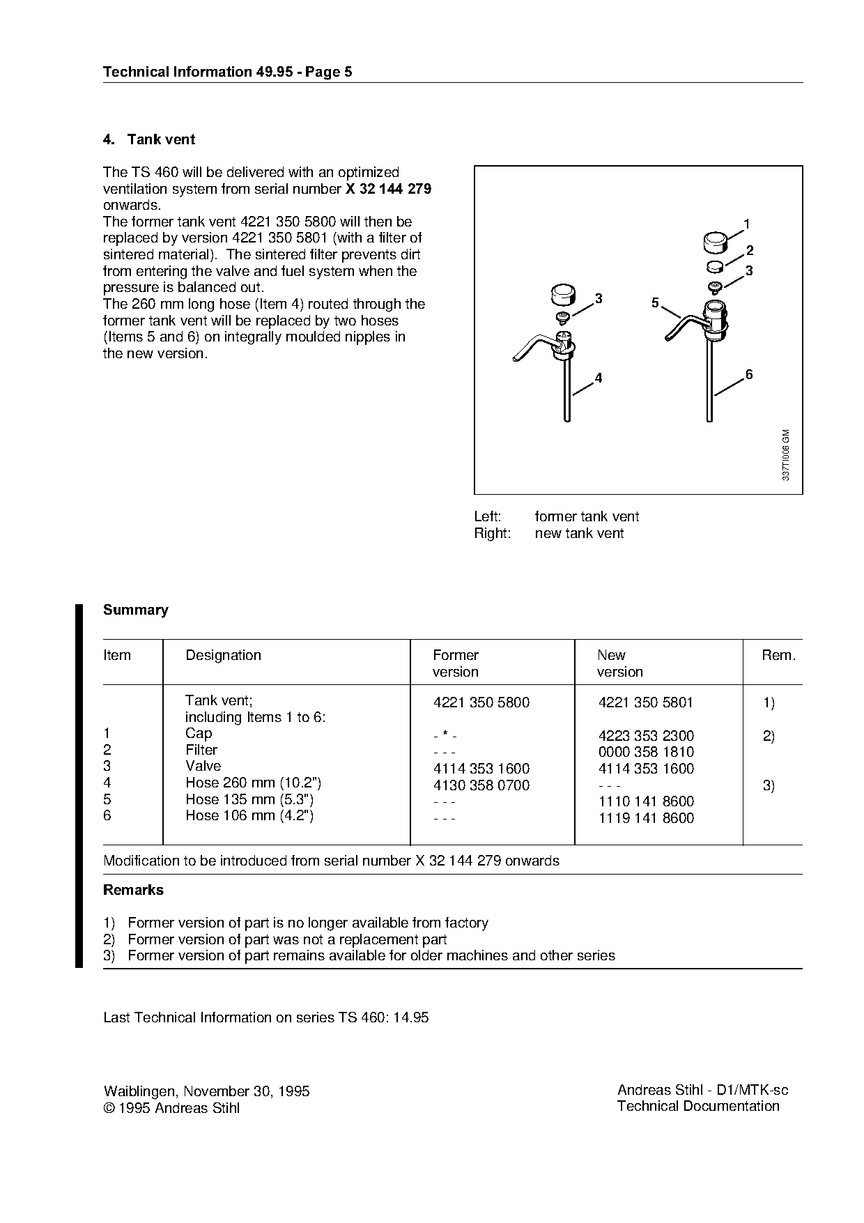
| 4221 350 5800 | 4221 350 5801 | The former tank vent 4221 350 5800 will then be 1 replaced by version 4221 350 5801 (with a filter of sintered material). |
Full text
Page 1 of 5
Text of page 1 — search, copy, screen readers
Technical Information

                                                                                                        49.95

Cut-off saws STIHL TS 460 - Type 4221

&RQWHQWV

1.   STIHL quick-starting system (ElastoStart, decompression valve), starter mechanism (rope rotor with bushing)
2.   Carburetor (type HS 276 A)
3.   Ignition module (standardization)
4.   Tank vent (with sintered filter)

1.=STIHL quick-starting system, starter mechanism

1.1=STIHL quick-starting system
From serial number X 32 675 830=onwards, the cut-off
machine STIHL TS 460 will generally be equipped
with the (ODVWR6WDUW starter mechanism and the

decompression valve=so that they can be started
more easily.

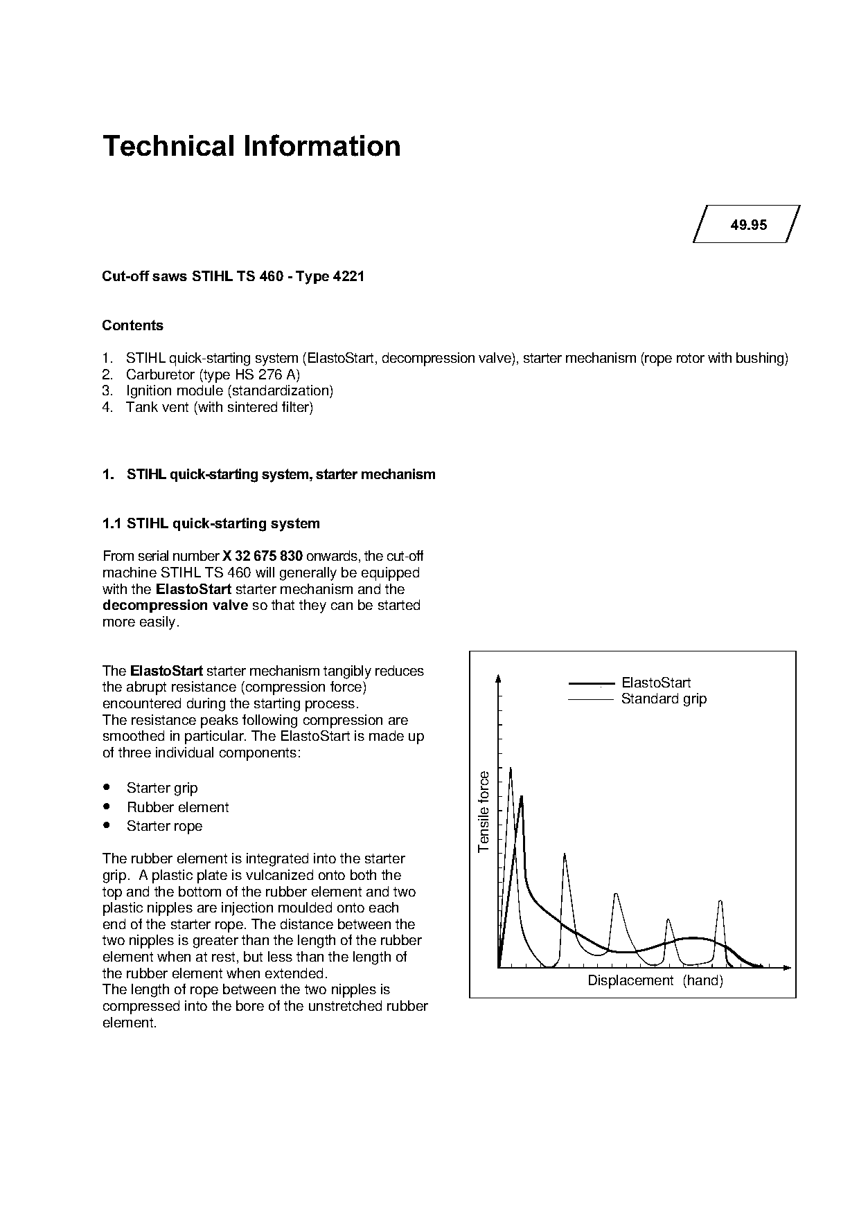
The (ODVWR6WDUW starter mechanism tangibly reduces
                                                                                      ElastoStart

the abrupt resistance (compression force)
encountered during the starting process.                                              Standard grip
The resistance peaks following compression are
smoothed in particular. The ElastoStart is made up

of three individual components:
                                                             Tensile force

• Starter grip

• Rubber element
• Starter rope

The rubber element is integrated into the starter
grip. A plastic plate is vulcanized onto both the
top and the bottom of the rubber element and two

plastic nipples are injection moulded onto each
end of the starter rope. The distance between the
two nipples is greater than the length of the rubber
element when at rest, but less than the length of
the rubber element when extended.                                                 Displacement (hand)
The length of rope between the two nipples is
compressed into the bore of the unstretched rubber
element.
Page 2 of 5
Text of page 2 — search, copy, screen readers
Technial Information 49.95 - Page 2

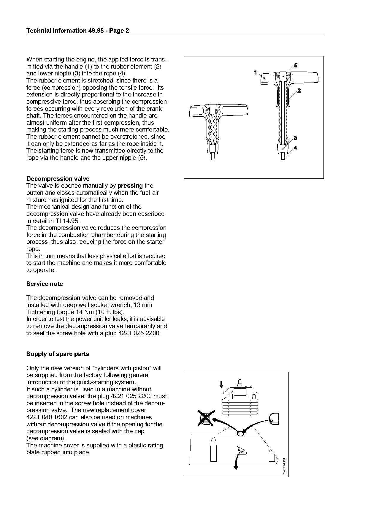
When starting the engine, the applied force is trans-
mitted via the handle (1) to the rubber element (2)
and lower nipple (3) into the rope (4).
The rubber element is stretched, since there is a
force (compression) opposing the tensile force. Its
extension is directly proportional to the increase in
compressive force, thus absorbing the compression
forces occurring with every revolution of the crank-
shaft. The forces encountered on the handle are
almost uniform after the first compression, thus
making the starting process much more comfortable.
The rubber element cannot be overstretched, since
it can only be extended as far as the rope inside it.

The starting force is now transmitted directly to the

rope via the handle and the upper nipple (5).

Decompression valve
The valve is opened manually by SUHVVLQJ the
button and closes automatically when the fuel-air

mixture has ignited for the first time.
The mechanical design and function of the
decompression valve have already been described
in detail in TI 14.95.
The decompression valve reduces the compression
force in the combustion chamber during the starting
process, thus also reducing the force on the starter
rope.

This in turn means that less physical effort is required
to start the machine and makes it more comfortable
to operate.

Service note

The decompression valve can be removed and
installed with deep well socket wrench, 13 mm
Tightening torque 14 Nm (10 ft. lbs).
In order to test the power unit for leaks, it is advisable

to remove the decompression valve temporarily and
to seal the screw hole with a plug 4221 025 2200.

Supply of spare parts

Only the new version of "cylinders with piston" will
be supplied from the factory following general
introduction of the quick-starting system.

If such a cylinder is used in a machine without
decompression valve, the plug 4221 025 2200 must
be inserted in the screw hole instead of the decom-
pression valve. The new replacement cover
4221 080 1602 can also be used on machines
without decompression valve if the opening for the
decompression valve is sealed with the cap
(see diagram).
The machine cover is supplied with a plastic rating
plate clipped into place.
                                                                               337TI004 KN
Page 3 of 5
Text of page 3 — search, copy, screen readers
Technical Information 49.95 - Page 3

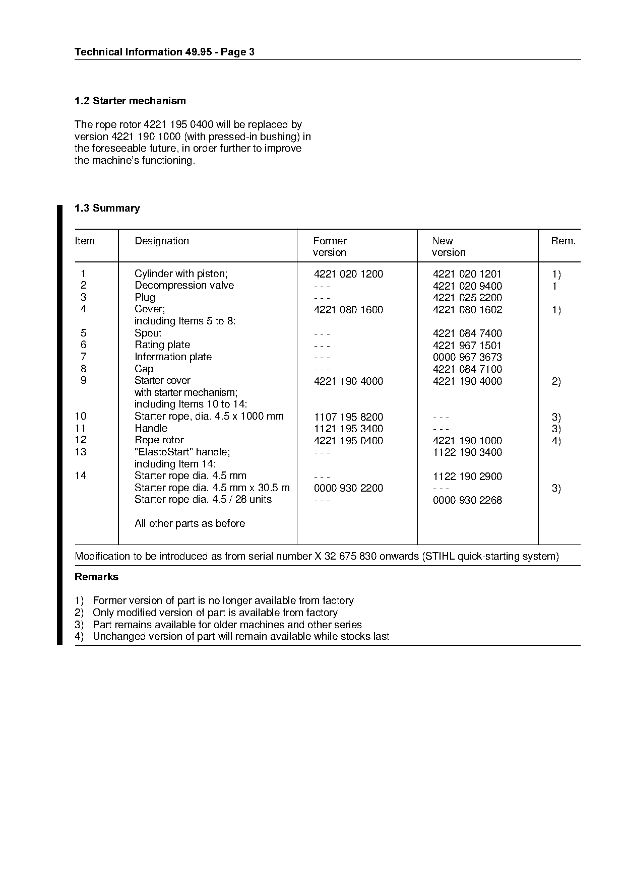
1.2=Starter mechanism

The rope rotor 4221 195 0400 will be replaced by
version 4221 190 1000 (with pressed-in bushing) in
the foreseeable future, in order further to improve
the machine’s functioning.

1.3=Summary

Item          Designation                             Former               New                      Rem.

                                                      version              version

 1            Cylinder with piston;                   4221 020 1200        4221 020 1201            1)
 2            Decompression valve                     ---                  4221 020 9400            1

 3            Plug                                    ---                  4221 025 2200
 4            Cover;                                  4221 080 1600        4221 080 1602            1)
              including Items 5 to 8:

 5            Spout                                   ---                  4221 084 7400
 6            Rating plate                            ---                  4221 967 1501
 7            Information plate                       ---                  0000 967 3673
 8
 9
              Cap
              Starter cover
                                                      ---       fo
                                                      4221 190 4000
                                                                           4221 084 7100
                                                                           4221 190 4000            2)
              with starter mechanism;
              including Items 10 to 14:
10            Starter rope, dia. 4.5 x 1000 mm        1107 195 8200        ---                      3)
11            Handle                                  1121 195 3400        ---                      3)

12            Rope rotor                              4221 195 0400        4221 190 1000            4)
13            "ElastoStart" handle;                   ---                  1122 190 3400
              including Item 14:
14            Starter rope dia. 4.5 mm                ---                  1122 190 2900

              Starter rope dia. 4.5 mm x 30.5 m       0000 930 2200        ---                      3)

              Starter rope dia. 4.5 / 28 units        ---                  0000 930 2268

              All other parts as before

Modification to be introduced as from serial number X 32 675 830 onwards (STIHL quick-starting system)

5HPDUNV

1)   Former version of part is no longer available from factory
2)   Only modified version of part is available from factory

3)   Part remains available for older machines and other series
4)   Unchanged version of part will remain available while stocks last
Page 4 of 5
Text of page 4 — search, copy, screen readers
Technial Information 49.95 - Page 4

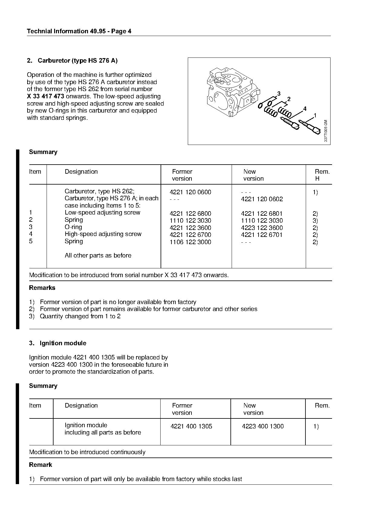
2.=Carburetor =type HS 276 A

Operation of the machine is further optimized
by use of the type HS 276 A carburetor instead
of the former type HS 262 from serial number
X 33 417 473=onwards. The low-speed adjusting                                               3
                                                                                                2
screw and high-speed adjusting screw are sealed
by new O-rings in this carburetor and equipped                                                      4
with standard springs.                                                                                  1

                                                                                                             337TI005 GM
6XPPDU\

Item         Designation                             Former                       New                   Rem.

                                                     version                      version               H

             Carburetor, type HS 262;                4221 120 0600            ---                       1)
             Carburetor, type HS 276 A; in each      ---                      4221 120 0602

             case including Items 1 to 5:
1            Low-speed adjusting screw               4221 122 6800            4221 122 6801             2)
2
3
4
             Spring
             O-ring
             High-speed adjusting screw
                                                     1110 122 3030
                                                     4221 122 3600
                                                                  fo          1110 122 3030
                                                                              4223 122 3600
                                                                                                        3)
                                                                                                        2)
                                                     4221 122 6700            4221 122 6701             2)
5            Spring                                  1106 122 3000
                                                                              ---                       2)

             All other parts as before

Modification to be introduced from serial number X 33 417 473 onwards.
5HPDUNV

1) Former version of part is no longer available from factory
2) Former version of part remains available for former carburetor and other series
3) Quantity changed from 1 to 2

3.=Ignition module

Ignition module 4221 400 1305 will be replaced by
version 4223 400 1300 in the foreseeable future in

order to promote the standardization of parts.

6XPPDU\

Item         Designation                             Former                       New                   Rem.
                                                     version                      version
             Ignition module                         4221 400 1305            4223 400 1300             1)
             including all parts as before

Modification to be introduced continuously

5HPDUN

1) Former version of part will only be available from factory while stocks last
Page 5 of 5
Text of page 5 — search, copy, screen readers
Technical Information 49.95 - Page 5

4.=Tank vent

The TS 460 will be delivered with an optimized
ventilation system from serial number X 32 144 27
onwards.
The former tank vent 4221 350 5800 will then be                                                        1
replaced by version 4221 350 5801 (with a filter of
sintered material). The sintered filter prevents dirt                                                  2
from entering the valve and fuel system when the                                                       3
pressure is balanced out.
The 260 mm long hose (Item 4) routed through the                                 3         5
former tank vent will be replaced by two hoses
(Items 5 and 6) on integrally moulded nipples in

the new version.

                                                                                 4                     6

                                                                                                                337TI006 GM
                                                              Left:
                                                              Right:
                                                                        former tank vent
                                                                        new tank vent

6XPPDU\

Item         Designation                                Former                   New                       Rem.

                                                        version                  version

             Tank vent;                                 4221 350 5800            4221 350 5801             1)
             including Items 1 to 6:
1            Cap                                        -*-                      4223 353 2300             2)

2            Filter                                     ---                      0000 358 1810
3            Valve                                      4114 353 1600            4114 353 1600
4            Hose 260 mm (10.2")                        4130 358 0700            ---                       3)

5            Hose 135 mm (5.3")                         ---                      1110 141 8600
6            Hose 106 mm (4.2")                         ---                      1119 141 8600

Modification to be introduced from serial number X 32 144 279 onwards
5HPDUNV

1) Former version of part is no longer available from factory
2) Former version of part was not a replacement part
3) Former version of part remains available for older machines and other series

Last Technical Information on series TS 460: 14.95

Waiblingen, November 30, 1995                                                        Andreas Stihl - D1/MTK-sc
© 1995 Andreas Stihl                                                                 Technical Documentation
Most of these PDFs embed fonts with a shifted character map, so the text above was recovered rather than copied — read it as a faithful but imperfect transcription, and treat the page image above each block as the authority where the two disagree — the figures exist only there, because they are vector drawings that text extraction cannot keep.