Technical Information · issue 1 of 1996
Servicing instructions 036 QS
IssueTI 1/1996
Engine family 1125
Full text
Page 1 of 8
Text of page 1 — search, copy, screen readers
Technical Information

                                                                                                                   01.96

Servicing Instructions for STIHL 036 QS - "Quickstop Super"  -  Series 1125

Inspection, maintenance and repair work may only be performed by properly trained and authorized personnel.

1.===Checking operation of chain======2.=Disassembly

=====brake =with bar and chain========2.1=Interlock lever

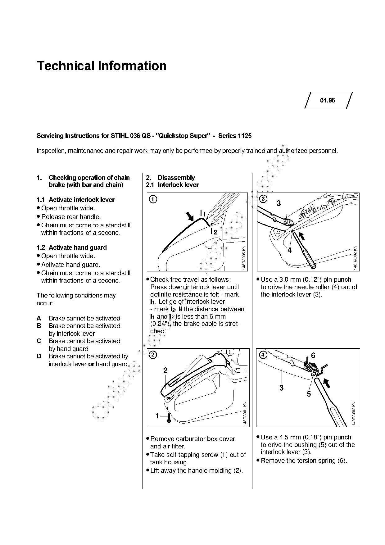
1.1=Activate interlock lever============N==================================================P
                                                                                                3
• Open throttle wide.

• Release rear handle.                                      l1
• Chain must come to a standstill
  within fractions of a second.                                   fo
                                                                 l2

1.2=Activate hand guard

                                                                                                                                148RA002 KN
                                                                         148RA035 KN
                                                                                                     4
• Open throttle wide.
• Activate hand guard.

• Chain must come to a standstill
 within fractions of a second.        • Check free travel as follows:                    • Use a 3.0 mm (0.12") pin punch
                                        Press down interlock lever until                  to drive the needle roller (4) out of
                                        definite resistance is felt - mark                the interlock lever (3).

The following conditions may
occurW==================================l1K=iet go of interlock lever

                                        - mark l2K=ff the distance between
$    Brake cannot be activated          l1=~nd l2=is less than 6 mm
%    Brake cannot be activated          (0.24"), the brake cable is stret-
     by interlock lever                 ched.

&    Brake cannot be activated
     by hand guard

'    Brake cannot be activated by       2                                                 4                    6
     interlock lever or=hand guard
                                                2

                                                                                                 3
                                                                                                           5

                                                                                                                             148RA003 KN
                                                                           148RA001 KN


                                      • Remove carburetor box cover                      • Use a 4.5 mm (0.18") pin punch
                                        and air filter.                                    to drive the bushing (5) out of the
                                      • Take self-tapping screw (1) out of                 interlock lever (3).
                                        tank housing.                                    • Remove the torsion spring (6).
                                      • Lift away the handle molding (2).
Page 2 of 8
Text of page 2 — search, copy, screen readers
Technical Information 01.96  -  Page 2

============================================================2.2=Exposing chain brake
  5
                          8 7                                                                                 9
                                                                                                                       9
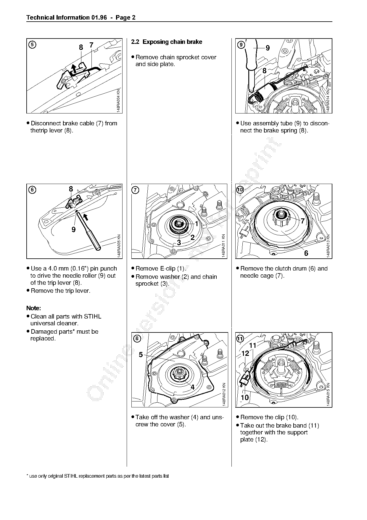
                                                            • Remove chain sprocket cover
                                                             and side plate.
                                                                                                                      8

                                             148RA004 KN

                                                                                                                                              148RA014 KN
• Disconnect brake cable (7) from                                                                            • Use assembly tube (9) to discon-
  thetrip lever (8).                                                                                          nect the brake spring (8).

  6                  8                                      7                                                10

                                                                                       1
                                                                                           fo                                        7
                      9
                                                                                             148RA011 KN
                                              148RA005 KN

                                                                                                                                               148RA013 KN
                                                                                   2
                                                                               3
                                                                                                                                      6

• Use a 4.0 mm (0.16") pin punch                            • Remove E-clip (1).                             • Remove the clutch drum (6) and
  to drive the needle roller (9) out                        • Remove washer (2) and chain                     needle cage (7).

  of the trip lever (8).                                     sprocket (3).
• Remove the trip lever.

1RWH
• Clean all parts with STIHL

  universal cleaner.
• Damaged parts* must be

  replaced.                                                  8                                               11
                                                                                                                11
                                                                 5                                            12

                                                                                               148RA012 KN

                                                                                                                                               148RA015 KN

                                                                                   4
                                                                                                              10

                                                            • Take off the washer (4) and uns-               • Remove the clip (10).
                                                             crew the cover (5).                             • Take out the brake band (11)
                                                                                                              together with the support
                                                                                                              plate (12).

* use only original STIHL replacement parts as per the latest parts list
Page 3 of 8
Text of page 3 — search, copy, screen readers
Technical Information 01.96  -  Page 3

12                                                          15   21                                               18          28

                                                             20
                                                                  19

                                             148RA017 KN

                                                                                                                                                          148RA023 KN
                                                                                                  148RA020 KN
                                13

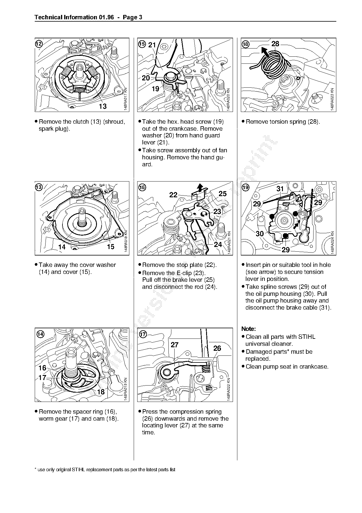
• Remove the clutch (13) (shroud,                           • Take the hex. head screw (19)                       • Remove torsion spring (28).
  spark plug).                                                out of the crankcase. Remove
                                                              washer (20) from hand guard
                                                              lever (21).

                                                            • Take screw assembly out of fan

                                                              housing. Remove the hand gu-
                                                              ard.

13                                                          16                                                    19            31

                                                                       22                    25
                                                                                                                       29                       29
                                                                                        23
                                              148RA018 KN

                                                                                                                       30
                                                                                                    148RA021 KN

                                                                                                                                                          148RA024 KN

           14                        15                                                 24
                                                                                                                                   29

• Take away the cover washer                                • Remove the stop plate (22).                         • Insert pin or suitable tool in hole
  (14) and cover (15).                                      • Remove the E-clip (23).                               (see arrow) to secure tension

                                                             Pull off the brake lever (25)                          lever in position.
                                                             and disconnect the rod (24).                         • Take spline screws (29) out of

                                                                                                                    the oil pump housing (30). Pull
                                                                                                                    the oil pump housing away and
                                                                                                                    disconnect the brake cable (31).

                                                                                                                  1RWH

 14                                                         17
                                                                                                                  • Clean all parts with STIHL
                                                                        27                                          universal cleaner.
                                                                                        26                        • Damaged parts* must be

                                                                                                                    replaced.
 16                                                                                                               • Clean pump seat in crankcase.

 17
                                             148RA019 KN

                                                                                                  148RA022 KN


• Remove the spacer ring (16),                              • Press the compression spring
  worm gear (17) and cam (18).                               (26) downwards and remove the
                                                             locating lever (27) at the same
                                                             time.

* use only original STIHL replacement parts as per the latest parts list
Page 4 of 8
Text of page 4 — search, copy, screen readers
Technical Information 01.96  -  Page 4

2.3=Oil pump housing==========================================================================================3.===Assembly
                                                                                                              Lubricate all moving parts (see
 20                                    3                       23                    7    8                   arrows in illustrations under 4) with
                                                                                                              oil or grease.
                                       2
                                           1

                                               148RA006 KN

                                                                                                148RA009 KN
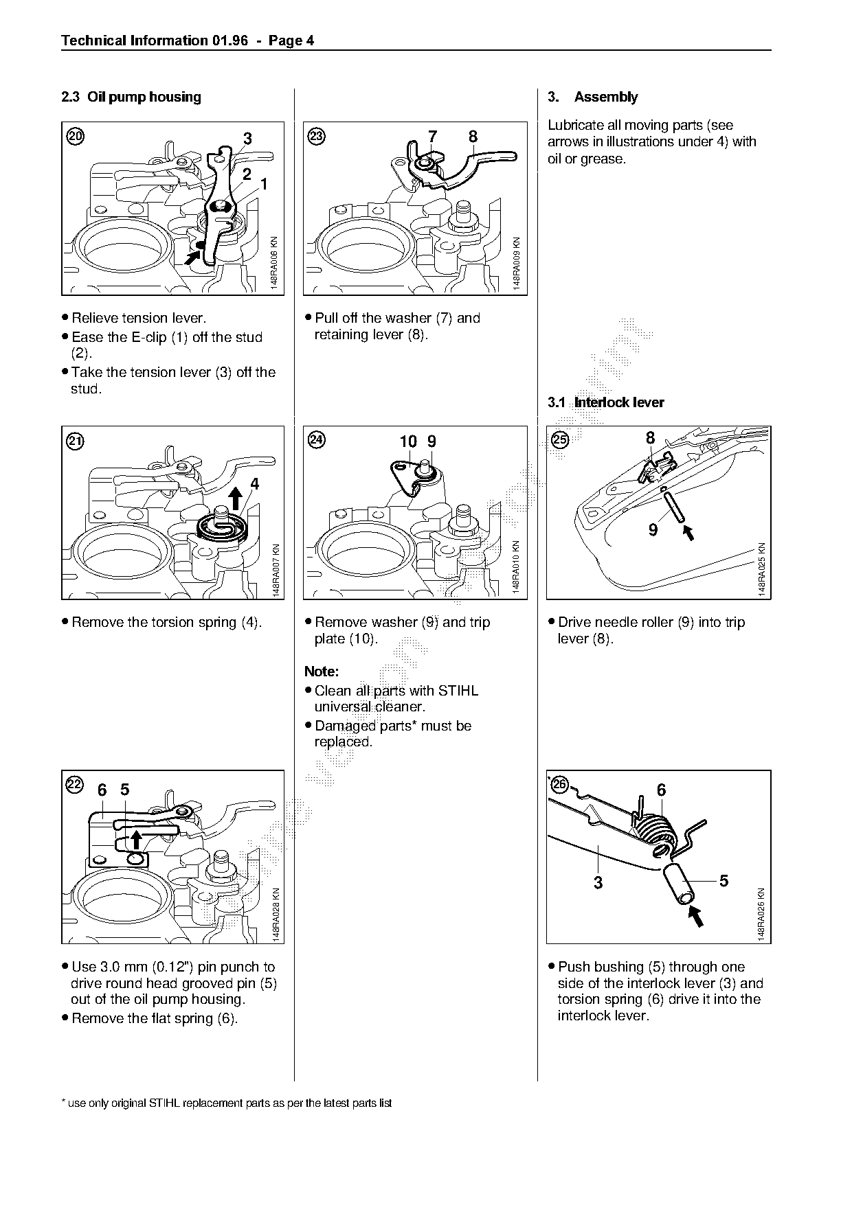
• Relieve tension lever.                                       • Pull off the washer (7) and
• Ease the E-clip (1) off the stud                              retaining lever (8).

  (2).
• Take the tension lever (3) off the
  stud.
                                                                                                              3.1=Interlock lever

 21                                                            24             10 9                            25               8

                                         4
                                                                                           fo  148RA010 KN


                                                                                                                                                      148RA025 KN
                                                 148RA007 KN

• Remove the torsion spring (4).                               • Remove washer (9) and trip                   • Drive needle roller (9) into trip
                                                                plate (10).                                    lever (8).

                                                               1RWH

                                                               • Clean all parts with STIHL
                                                                universal cleaner.
                                                               • Damaged parts* must be

                                                                replaced.

 22                                                                                                           26
       6 5                                                                                                                         6

                                                                                                                      3                     5

                                                                                                                                                      148RA026 KN
                                                 148RA028 KN

• Use 3.0 mm (0.12") pin punch to                                                                             • Push bushing (5) through one
  drive round head grooved pin (5)                                                                             side of the interlock lever (3) and
  out of the oil pump housing.                                                                                 torsion spring (6) drive it into the
• Remove the flat spring (6).                                                                                  interlock lever.

* use only original STIHL replacement parts as per the latest parts list
Page 5 of 8
Text of page 5 — search, copy, screen readers
Technical Information 01.96  -  Page 5

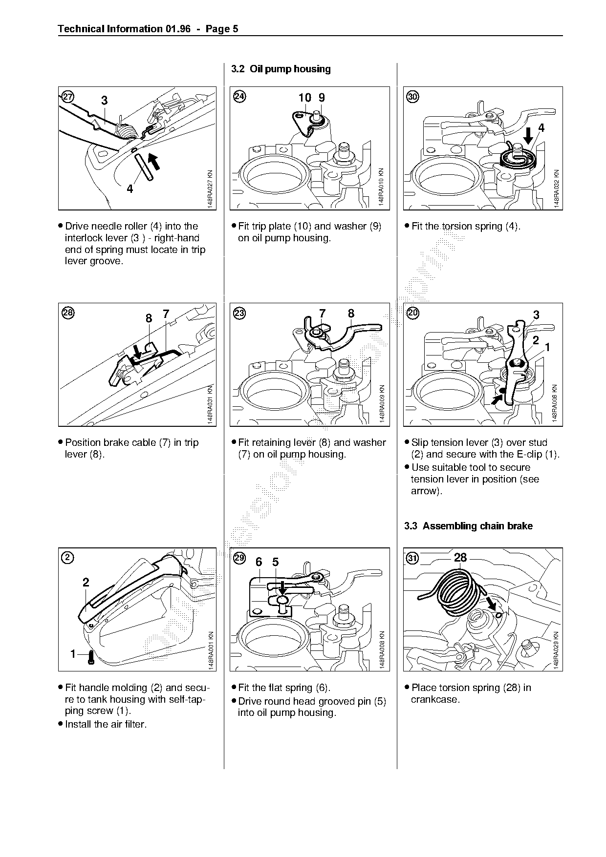
                                                     3.2=Oil pump housing

 27                                                  24              10 9                              30
             3


                                                                                        148RA010 KN

                                                                                                                                                   148RA032 KN
                                      148RA027 KN
                 4

• Drive needle roller (4) into the                   • Fit trip plate (10) and washer (9)              • Fit the torsion spring (4).
 interlock lever (3 ) - right-hand                    on oil pump housing.

 end of spring must locate in trip

 lever groove.

 28
                     8 7
                                                     23                  7       8                      20                              3

                                                                                                                                        2
                                                                                                                                            1

                                                                                                                                                148RA006 KN
                                                                                         148RA009 KN
                                      148RA031 KN

• Position brake cable (7) in trip                   • Fit retaining lever (8) and washer              • Slip tension lever (3) over stud
 lever (8).                                           (7) on oil pump housing.                          (2) and secure with the E-clip (1).
                                                                                                       • Use suitable tool to secure

                                                                                                        tension lever in position (see

                                                                                                        arrow).

=======================================================================================================3.3=Assembling chain brake

 2                                                   29
                                                          6 5                                          31          28


                                                                                         148RA008 KN

                                                                                                                                                  148RA029 KN
                                       148RA001 KN


• Fit handle molding (2) and secu-                   • Fit the flat spring (6).                        • Place torsion spring (28) in
  re to tank housing with self-tap-                  • Drive round head grooved pin (5)                 crankcase.
  ping screw (1).                                     into oil pump housing.
• Install the air filter.
Page 6 of 8
Text of page 6 — search, copy, screen readers
Technical Information 01.96  -  Page 6

17                                                   15   21                                             12

             27              26

                                                      20
                                                           19

                                                                                                                                            148RA017 KN
                                      148RA022 KN

                                                                                        148RA020 KN
                                                                                                                                      13

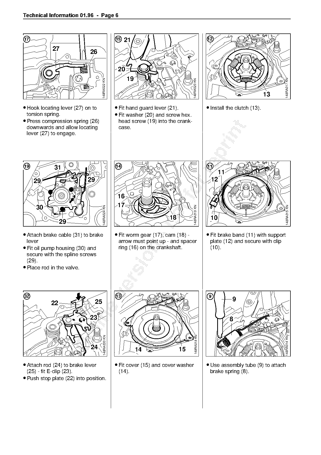
• Hook locating lever (27) on to                     • Fit hand guard lever (21).                        • Install the clutch (13).
  torsion spring.                                    • Fit washer (20) and screw hex.
• Press compression spring (26)                       head screw (19) into the crank-

  downwards and allow locating                        case.

  lever (27) to engage.

19           31                                      14                                                  11

                                                                                                             11
     29                     29                                                                             12

                                                      16
     30                                               17
                                                                                         148RA019 KN

                                                                                                                                              148RA015 KN
                                       148RA024 KN

                                                                            18                            10
                 29

• Attach brake cable (31) to brake                   • Fit worm gear (17), cam (18) -                    • Fit brake band (11) with support
  lever                                               arrow must point up - and spacer                    plate (12) and secure with clip
• Fit oil pump housing (30) and

                                                      ring (16) on the crankshaft.                        (10).
  secure with the spline screws

  (29).
• Place rod in the valve.

32                                                   13                                                   9
                                 25                                                                                  9
            22

                             23                                                                                     8

                                                                                           148RA018 KN
                                       148RA030 KN

                                                                                                                                            148RA014 KN

                              24                                14               15

• Attach rod (24) to brake lever                     • Fit cover (15) and cover washer                   • Use assembly tube (9) to attach
  (25) - fit E-clip (23).                             (14).                                               brake spring (8).
• Push stop plate (22) into position.
Page 7 of 8
Text of page 7 — search, copy, screen readers
Technical Information 01.96  -  Page 7

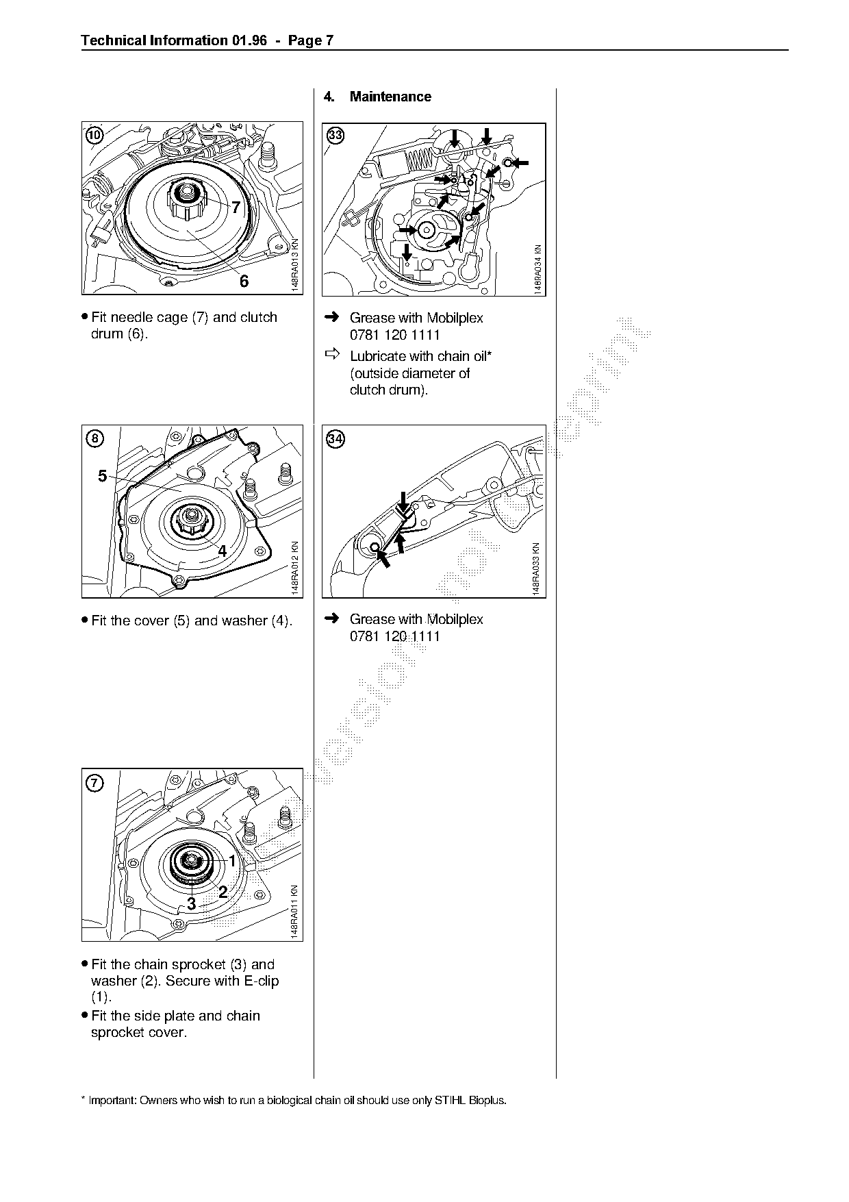
                                                          4.===Maintenance

 10                                                       33


                                            148RA013 KN

                                                                                            148RA034 KN
                                    6

• Fit needle cage (7) and clutch                          ➜ Grease with Mobilplex
  drum (6).                                                    0781 120 1111

                                                          Ø Lubricate with chain oil

                                                               (outside diameter of
                                                               clutch drum).

  8                                                       34

      5
                                            148RA012 KN

                                                                                            148RA033 KN
                            4

• Fit the cover (5) and washer (4).                       ➜ Grease with Mobilplex
                                                               0781 120 1111


                                1
                                           148RA011 KN

                            2
                      3

• Fit the chain sprocket (3) and
  washer (2). Secure with E-clip
  (1).
• Fit the side plate and chain
  sprocket cover.

* Important: Owners who wish to run a biological chain oil should use only STIHL Bioplus.
Page 8 of 8
Text of page 8 — search, copy, screen readers
Technical Information 01.96 - Page 8
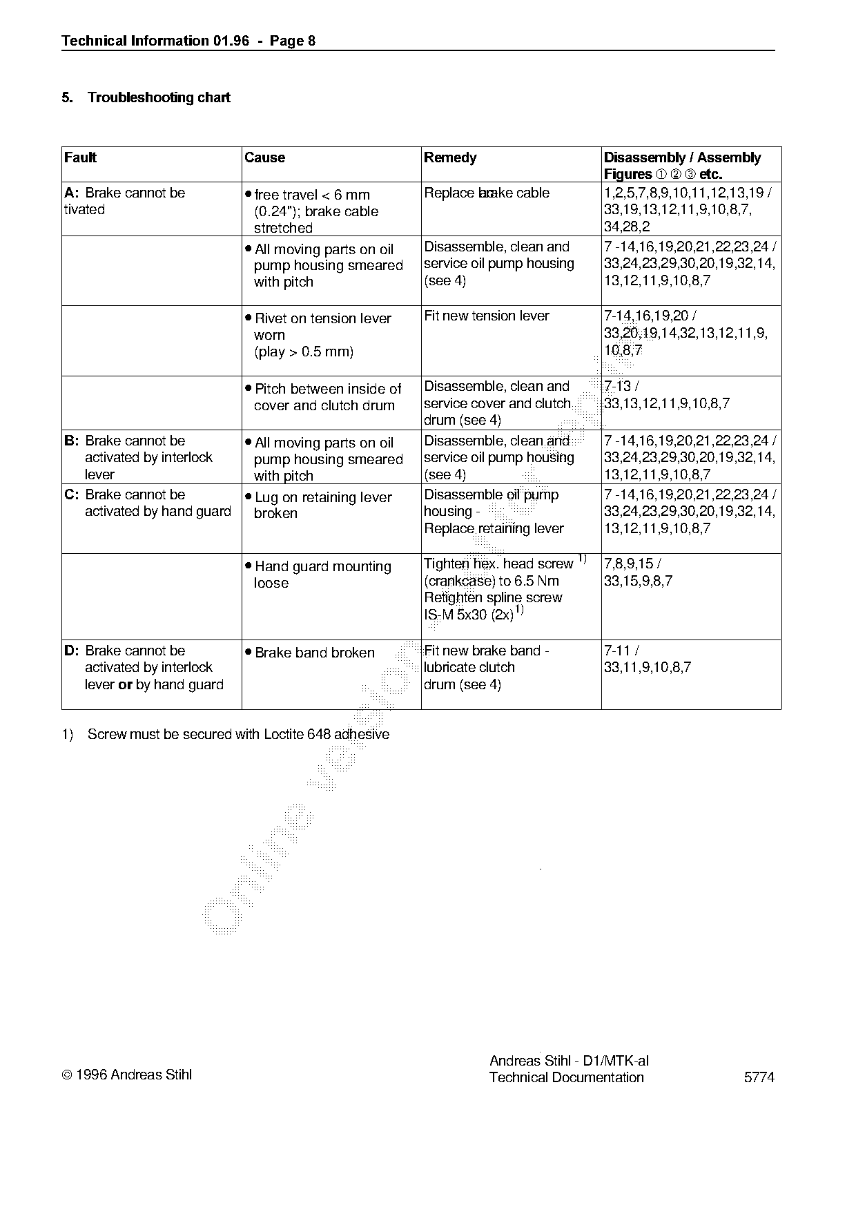
5.===Troubleshooting chart
Fault========================Cause=======================Remedy=======================Disassembly / Assembly
Figures ➀ ➁ ➂ etc.
A:=_rake cannot be • free travel < 6 mm ac- cable
Replace brake 1,2,5,7,8,9,10,11,12,13,19 /
tivated (0.24"); brake cable 33,19,13,12,11,9,10,8,7,
stretched 34,28,2
• All moving parts on oil Disassemble, clean and 7 -14,16,19,20,21,22,23,24 /
pump housing smeared service oil pump housing 33,24,23,29,30,20,19,32,14,
with pitch (see 4) 13,12,11,9,10,8,7
• Rivet on tension lever Fit new tension lever 7-14,16,19,20 /
worn 33,20,19,14,32,13,12,11,9,
(play > 0.5 mm) 10,8,7
• Pitch between inside of Disassemble, clean and 7-13 /
cover and clutch drum service cover and clutch 33,13,12,11,9,10,8,7
drum (see 4)
B:=_rake cannot be • All moving parts on oil Disassemble, clean and 7 -14,16,19,20,21,22,23,24 /
activated by interlock pump housing smeared service oil pump housing 33,24,23,29,30,20,19,32,14,
lever with pitch (see 4) 13,12,11,9,10,8,7
C:=_rake cannot be • Lug on retaining lever Disassemble oil pump 7 -14,16,19,20,21,22,23,24 /
activated by hand guard broken housing -fo
Replace retaining lever
33,24,23,29,30,20,19,32,14,
13,12,11,9,10,8,7
• Hand guard mounting Tighten hex. head screw 1) 7,8,9,15 /
loose (crankcase) to 6.5 Nm 33,15,9,8,7
Retighten spline screw
IS-M 5x30 (2x)1)
D:=_rake cannot be • Brake band broken Fit new brake band - 7-11 /
activated by interlock lubricate clutch 33,11,9,10,8,7
lever RU by hand guard
drum (see 4)
1) Screw must be secured with Loctite 648 adhesive
Andreas Stihl - D1/MTK-al
1996 Andreas Stihl Technical Documentation 5774 Most of these PDFs embed fonts with a shifted character map, so the text above was recovered rather than copied — read it as a faithful but imperfect transcription, and treat the page image above each block as the authority where the two disagree — the figures exist only there, because they are vector drawings that text extraction cannot keep.