Technical Information · issue 12 of 1996
Tank housing; air filter system with compensator;
Model 026 will be available in future in a version
Part changes (2)
| Was | Becomes | What the bulletin says |
|---|---|---|
| 1121 182 0900 | 1125 182 0901 | In order to standardize parts the original switch shaft 1121 182 0900 will be replaced by switch shaft 1125 182 0901 from machine number X 33 339 218. |
| 1121 442 1600 | 1125 442 1600 | The original contact spring 1121 442 1600 will be replaced by the version 1125 442 1600 to coincide with the introduction of the new carburetor heating system. |
Full text
Page 1 of 6
Text of page 1 — search, copy, screen readers
Technical Information

                                                                                                          12.96

Model 024, 026 Chainsaws  -  Series 1121

&RQWHQWV

1. Tank housing (modified shape),                            2.3 Wiring harness, ground wire, insulating tube

    switch shaft (standardizing parts)                       2.4 Installing wiring harness
2. New 026 VH ARCTIC PRO version                             2.5 Summary
    (with electric carb heating)                             3. Intake air preheating kit

2.1 Carburetor (thermostatic switch, heating                     (cover on carburetor box cover)
    element, heating plate)                                  4. Nameplate (plastic)
2.2 Contact spring (with connector tag)

1.=====Tank housing, switch shaft
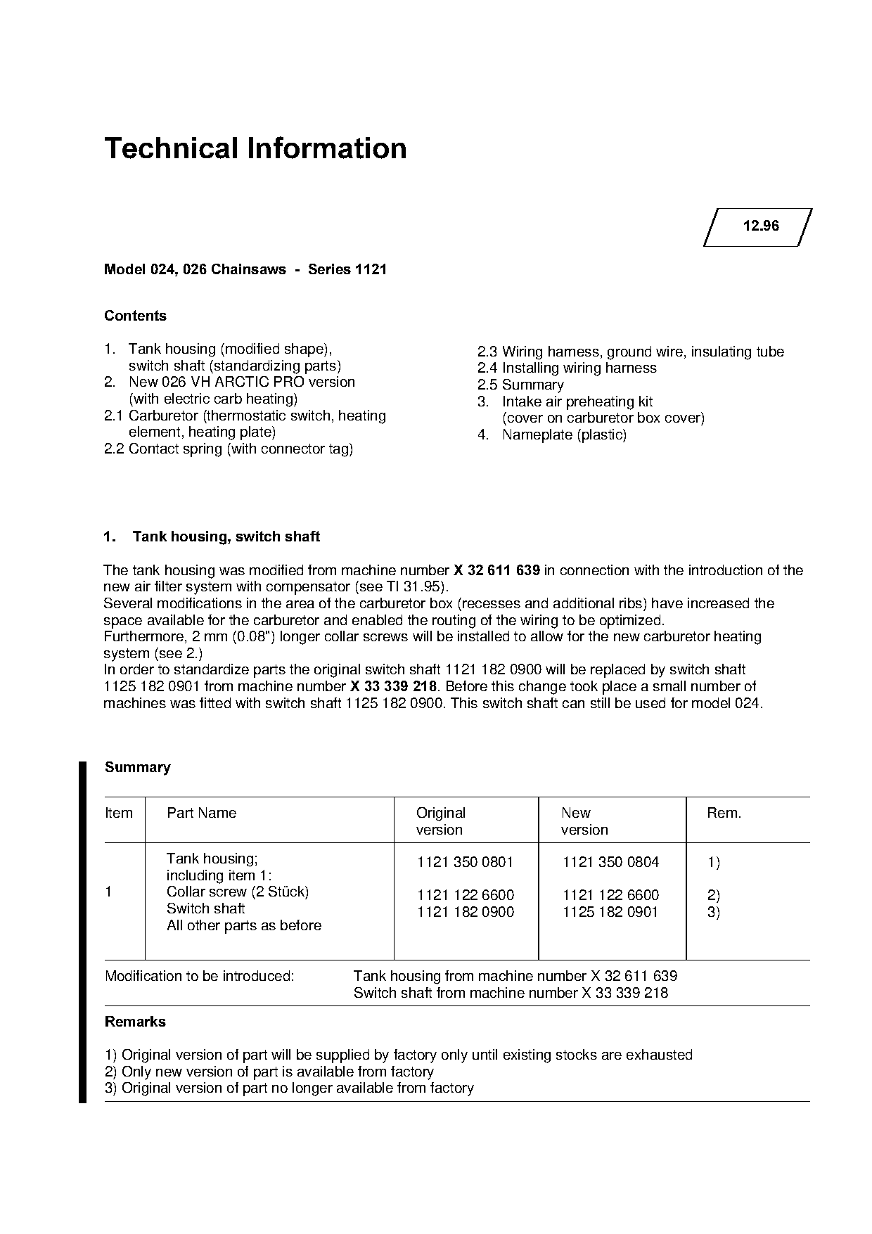
The tank housing was modified from machine number X 32 611 639=in connection with the introduction of the
new air filter system with compensator (see TI 31.95).
Several modifications in the area of the carburetor box (recesses and additional ribs) have increased the

space available for the carburetor and enabled the routing of the wiring to be optimized.
Furthermore, 2 mm (0.08") longer collar screws will be installed to allow for the new carburetor heating
system (see 2.)

In order to standardize parts the original switch shaft 1121 182 0900 will be replaced by switch shaft
1125 182 0901 from machine number X 33 339 218K=_efore this change took place a small number of

machines was fitted with switch shaft 1125 182 0900. This switch shaft can still be used for model 024.

6XPPDU\

Item       Part Name                              Original                New                      Rem.
                                                  version                 version

           Tank housing;                          1121 350 0801           1121 350 0804            1)
           including item 1:
1          Collar screw (2 Stück)                 1121 122 6600           1121 122 6600            2)

           Switch shaft                           1121 182 0900           1125 182 0901            3)
           All other parts as before

Modification to be introduced:          Tank housing from machine number X 32 611 639
                                        Switch shaft from machine number X 33 339 218
5HPDUNV

1) Original version of part will be supplied by factory only until existing stocks are exhausted
2) Only new version of part is available from factory
3) Original version of part no longer available from factory
Page 2 of 6
Text of page 2 — search, copy, screen readers
Technical Information 12.96  -  Page 2

2.===New 026 VH ARCTIC PRO version

Model 026 will be available in future in a version
with a fully automatic carburetor heating system
(“VH”).
At low outside temperatures the carburetor is
heated to a level that avoids icing.

2.1=Carburetor
                                                                         1          2                 3
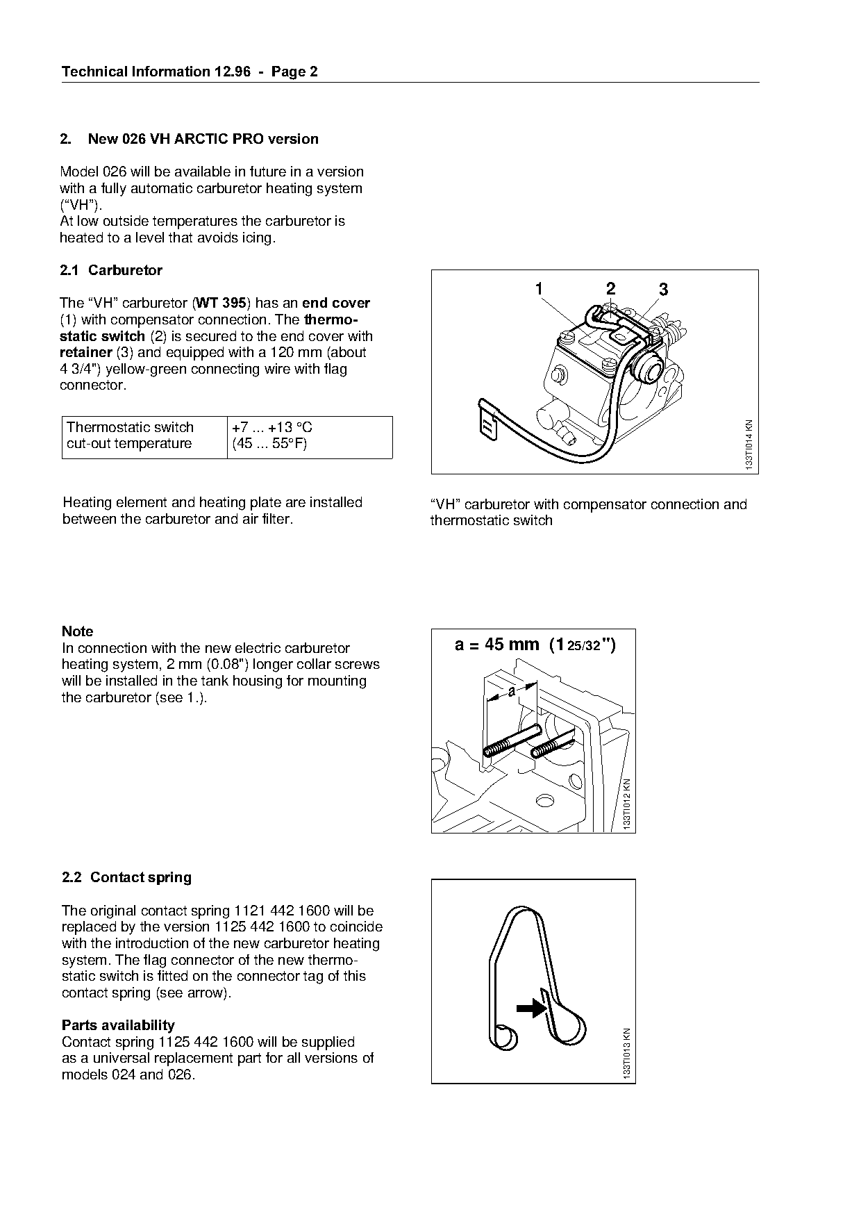
The “VH” carburetor EWT 395F=has an end cover
(1) with compensator connection. The thermo-
static switch=EOF=is secured to the end cover with

UHWDLQHU (3) and equipped with a 120 mm (about

4 3/4") yellow-green connecting wire with flag
connector.

                                                                                                          133TI014 KN
 Thermostatic switch        +7 ... +13 °C
 cut-out temperature        (45 ... 55°F)

Heating element and heating plate are installed
between the carburetor and air filter.                           fo
                                                          “VH” carburetor with compensator connection and
                                                          thermostatic switch

1RWH
In connection with the new electric carburetor               a = 45 mm (1 25/32 ")

heating system, 2 mm (0.08") longer collar screws
will be installed in the tank housing for mounting

the carburetor (see 1.).                                             a

                                                                                        133TI012 KN

2.2=Contact spring

The original contact spring 1121 442 1600 will be
replaced by the version 1125 442 1600 to coincide
with the introduction of the new carburetor heating
system. The flag connector of the new thermo-
static switch is fitted on the connector tag of this
contact spring (see arrow).

Parts availability
                                                                                        133TI013 KN

Contact spring 1125 442 1600 will be supplied
as a universal replacement part for all versions of
models 024 and 026.
Page 3 of 6
Text of page 3 — search, copy, screen readers
Technical Information 12.96  -  Page 3

2.3===Wiring harness, ground wire,
      insulating tube

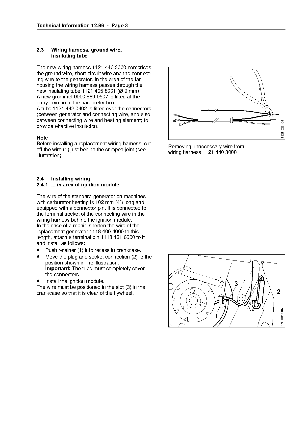
The new wiring harness 1121 440 3000 comprises
the ground wire, short circuit wire and the connect-
ing wire to the generator. In the area of the fan
housing the wiring harness passes through the
new insulating tube 1121 405 8001 (Ø 9 mm).
A new grommet 0000 989 0507 is fitted at the
entry point in to the carburetor box.
A tube 1121 442 0402 is fitted over the connectors
(between generator and connecting wire, and also
between connecting wire and heating element) to

                                                                                            133TI026 KN
provide effective insulation.

1RWH
Before installing a replacement wiring harness, cut

                                                       Removing unnecessary wire from
off the wire (1) just behind the crimped joint (see
                                                       wiring harness 1121 440 3000
illustration).

2.4=Installing wiring
2.4.1=... in area of ignition module====================fo
The wire of the standard generator on machines
with carburetor heating is 102 mm (4”) long and
equipped with a connector pin. It is connected to

the terminal socket of the connecting wire in the
wiring harness behind the ignition module.
In the case of a repair, shorten the wire of the
replacement generator 1118 400 4000 to this

length, attach a terminal pin 1118 431 6600 to it
and install as follows:

• Push retainer (1) into recess in crankcase.
• Move the plug and socket connection (2) to the
     position shown in the illustration.

     Important: qhe tube must completely cover
     the connectors.
• Install the ignition module.

The wire must be positioned in the slot (3) in the
                                                                                 3
crankcase so that it is clear of the flywheel.                                          2

                                                                                            133TI017 KN

                                                                         1
Page 4 of 6
Text of page 4 — search, copy, screen readers
Technical Information 12.96  -  Page 4

2.4.2=... in the carburetor box

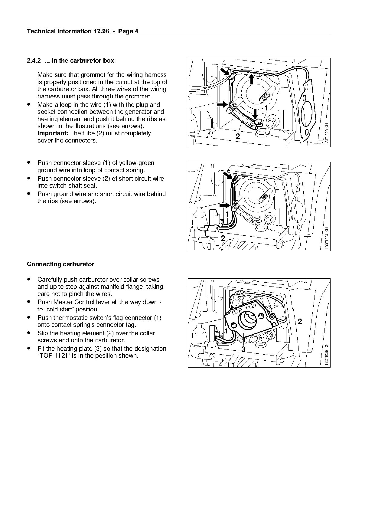
    Make sure that grommet for the wiring harness
    is properly positioned in the cutout at the top of
    the carburetor box. All three wires of the wiring
    harness must pass through the grommet.
•   Make a loop in the wire (1) with the plug and
    socket connection between the generator and
                                                                                      1
    heating element and push it behind the ribs as

                                                                                              133TI023 KN
    shown in the illustrations (see arrows).
    Important: qhe tube (2) must completely
    cover the connectors.
                                                                       2

• Push connector sleeve (1) of yellow-green
    ground wire into loop of contact spring.
• Push connector sleeve (2) of short circuit wire

    into switch shaft seat.
• Push ground wire and short circuit wire behind

    the ribs (see arrows).


                                                                                              133TI024 KN
                                                              2

Connecting carburetor

• Carefully push carburetor over collar screws
    and up to stop against manifold flange, taking

    care not to pinch the wires.

•   Push Master Control lever all the way down -
                                                                                  1
    to “cold start” position.                                                  112
                                                                      TOP
•   Push thermostatic switch’s flag connector (1)
    onto contact spring’s connector tag.                                                  2

•   Slip the heating element (2) over the collar               1
    screws and onto the carburetor.

•
                                                                                              133TI025 KN

    Fit the heating plate (3) so that the designation                      3
    “TOP 1121” is in the position shown.
Page 5 of 6
Text of page 5 — search, copy, screen readers
Technical Information 12.96  -  Page 5

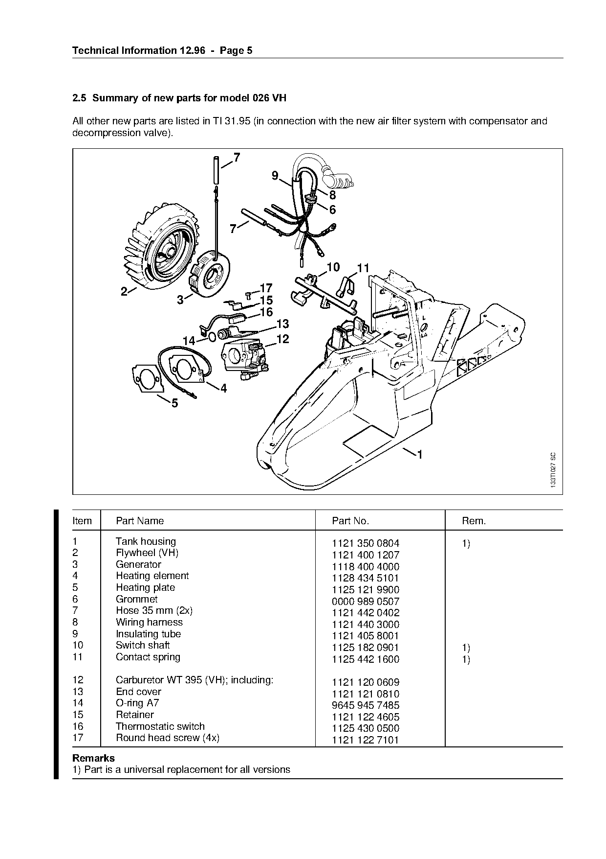
2.5=Summary of new parts for model 026 VH

All other new parts are listed in TI 31.95 (in connection with the new air filter system with compensator and
decompression valve).

                                      7
                                              9
                                                          8
                                                          6
                                      7

                                                          10     11
                                           17

           2
                        3                  15
                                           16
                                                13

                           14                   12
                                  4
                       5


                                                                                                                133TI027 SC

Item      Part Name                                        Part No.                      Rem.

1         Tank housing                                     1121 350 0804                 1)
2         Flywheel (VH)

                                                           1121 400 1207
3         Generator                                        1118 400 4000
4         Heating element                                  1128 434 5101
5         Heating plate                                    1125 121 9900

6         Grommet                                          0000 989 0507
7         Hose 35 mm (2x)                                  1121 442 0402
8         Wiring harness                                   1121 440 3000

9         Insulating tube                                  1121 405 8001
10        Switch shaft                                     1125 182 0901                 1)
11        Contact spring                                   1125 442 1600                 1)

12        Carburetor WT 395 (VH); including:               1121 120 0609
13        End cover                                        1121 121 0810
14        O-ring A7                                        9645 945 7485
15        Retainer                                         1121 122 4605
16        Thermostatic switch                              1125 430 0500
17        Round head screw (4x)                            1121 122 7101
5HPDUNV
1) Part is a universal replacement for all versions
Page 6 of 6
Text of page 6 — search, copy, screen readers
Technical Information 12.96 - Page 6
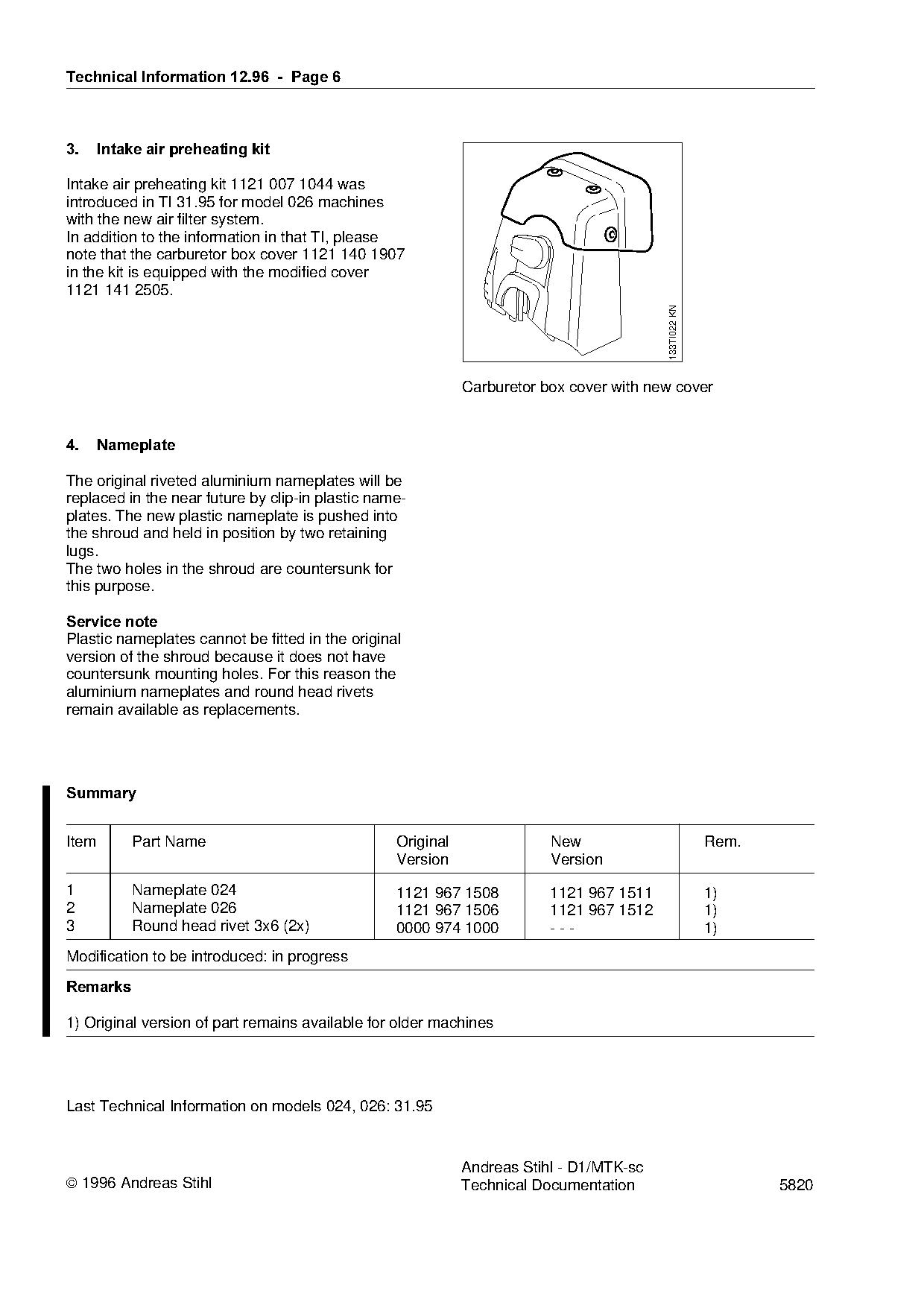
3.=====Intake air preheating kit
Intake air preheating kit 1121 007 1044 was
introduced in TI 31.95 for model 026 machines
with the new air filter system.
In addition to the information in that TI, please
note that the carburetor box cover 1121 140 1907
in the kit is equipped with the modified cover
1121 141 2505.
133TI022 KN
Carburetor box cover with new cover
4.=====Nameplate
The original riveted aluminium nameplates will be
replaced in the near future by clip-in plastic name-
plates. The new plastic nameplate is pushed into
the shroud and held in position by two retaining
lugs.
The two holes in the shroud are countersunk for
this purpose.
Service note
Plastic nameplates cannot be fitted in the original
version of the shroud because it does not have
countersunk mounting holes. For this reason the
aluminium nameplates and round head rivets
remain available as replacements.
6XPPDU\
Item Part Name Original New Rem.
Version Version
1 Nameplate 024 1121 967 1508 1121 967 1511 1)
2 Nameplate 026
1121 967 1506 1121 967 1512 1)
3 Round head rivet 3x6 (2x) 0000 974 1000 --- 1)
Modification to be introduced: in progress
5HPDUNV
1) Original version of part remains available for older machines
Last Technical Information on models 024, 026: 31.95
Andreas Stihl - D1/MTK-sc
1996 Andreas Stihl Technical Documentation 5820 Most of these PDFs embed fonts with a shifted character map, so the text above was recovered rather than copied — read it as a faithful but imperfect transcription, and treat the page image above each block as the authority where the two disagree — the figures exist only there, because they are vector drawings that text extraction cannot keep.