Technical Information · issue 15 of 1996
RE 102 KM, RE 104 KM, RE 106 KM, RE 102 K: Automat
IssueTI 15/1996
Full text
Page 1 of 9
Text of page 1 — search, copy, screen readers
Technical Information

                                                                                                   15.96

STIHL High-pressure Cleaner - Type 4719
   RE 102 KM
   RE 104 KM
   RE 106 KM

   E 102 K (some markets)

Contents

1. Automatic cutout (improved feature)
2. Pressure delay valve (improved feature)            2. Pressure Delay Valve
3. Safety control block (incorporating automatic
   cutout and pressure delay valve)
                                                      The pressure delay valve keeps a connecting port
4. Structure and function of automatic cutout and     between the delivery and intake sides of the high-
   pressure delay valve (diagram)                     pressure pump open during the starting phase.
5. Spray attachment (optimised shape and structure,   This reduces the electric motor start-up current.
    bayonet fixing/quick-release connection)

6. Casing
7. New spare parts                                    3. Safety Control Block
8. Valve block/pump casing connection (higher
   tightening torque)                                 The automatic cutout and pressure delay valve are

9. Service notes (adjusting pressure control,         built into the safety control block. In the new version,

   adjusting the microswitch, wiring diagram).        the control piston is not screwed into place but in-
   France only: RE 106 KM, safety control block       serted into the casing and secured with a U-faste-
                                                      ner.

From January 1996, high-pressure cleaners of series   The pressure control knob is no longer required.
RE 102/104/106 KM and, on some markets, RE 102 K      The operating pressure is adjusted on the spray

are equipped with a modified spray attachment,        lance of the new spray attachment.
automatic cutout and a pressure delay valve.
                                                      On the RE 102 K/KM and RE 104 KM, the banjo
For France, the stainless steel pistons previously    bolt fastening the non-return valve to the casing

used have been replaced by ceramic-coated pi-         has been replaced by connector 4719 510 1600.
stons.                                                See “New Spare Parts”.

                                                      On the RE 106 KM, the high-pressure hose outlet
1. Automatic Cutout                                   is unchanged.

The automatic cutout switches off the motor when
the spray gun is closed. This                         4. Structure and Function of the Automatic
• saves energy                                           Cutout and Pressure Delay Valve (Diagram)
• reduces noise
                                                      The structure and function of the automatic cutout
• makes operation easier.
                                                      and pressure delay valve are included in the des-
                                                      cription of the function of the safety control block
                                                      below.
Page 2 of 9
Text of page 2 — search, copy, screen readers
Technical Information 15.96 - Page 2

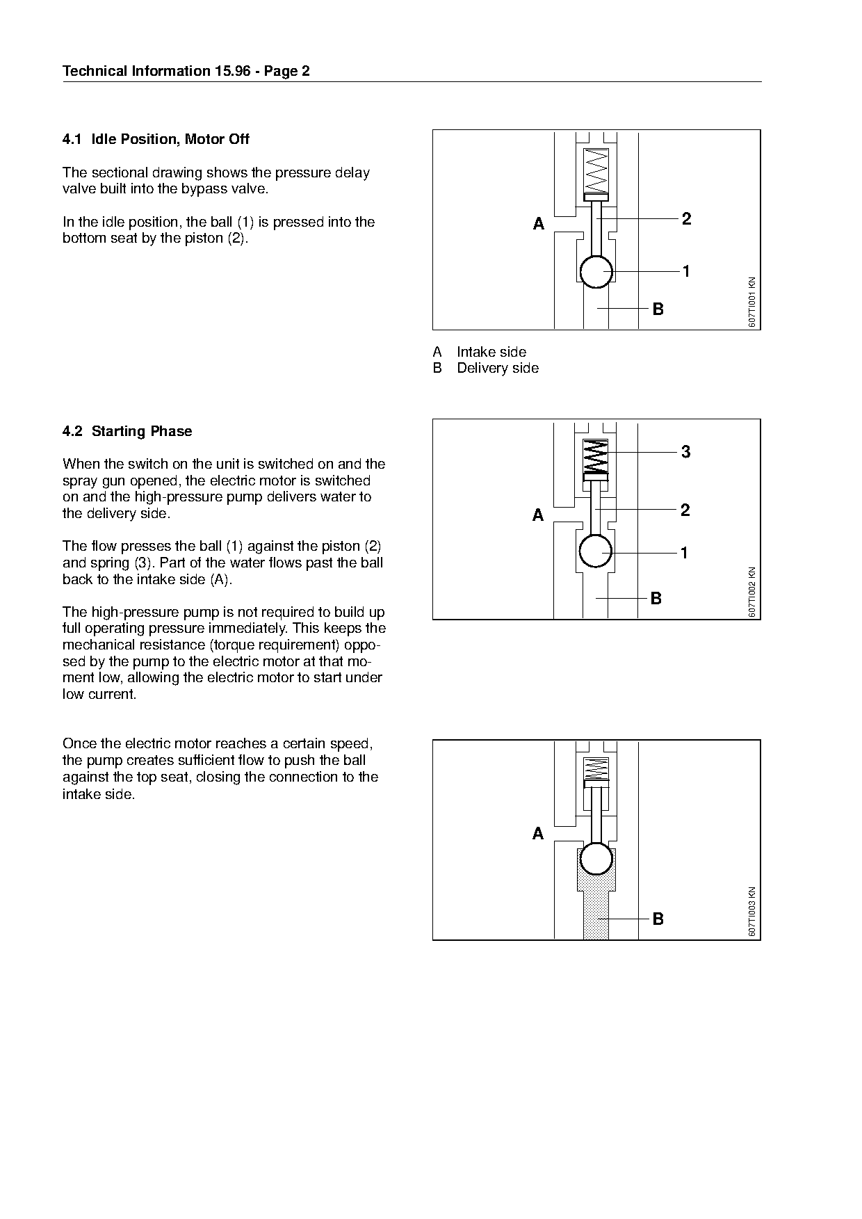
4.1 Idle Position, Motor Off

The sectional drawing shows the pressure delay
valve built into the bypass valve.

In the idle position, the ball (1) is pressed into the                      A             2
bottom seat by the piston (2).


                                                                                              607TI001 KN
                                                                                      B

                                                             A   Intake side

                                                             B   Delivery side

4.2 Starting Phase
                                                                                          3

When the switch on the unit is switched on and the
spray gun opened, the electric motor is switched
on and the high-pressure pump delivers water to
the delivery side.                                                  fo      A             2

The flow presses the ball (1) against the piston (2)
                                                                                          1
and spring (3). Part of the water flows past the ball

                                                                                              607TI002 KN
back to the intake side (A).

                                                                                      B
The high-pressure pump is not required to build up
full operating pressure immediately. This keeps the
mechanical resistance (torque requirement) oppo-

sed by the pump to the electric motor at that mo-
ment low, allowing the electric motor to start under

low current.

Once the electric motor reaches a certain speed,

the pump creates sufficient flow to push the ball
against the top seat, closing the connection to the

intake side.


                                                                                              607TI003 KN

                                                                                      B
Page 3 of 9
Text of page 3 — search, copy, screen readers
Technical Information 15.96 - Page 3

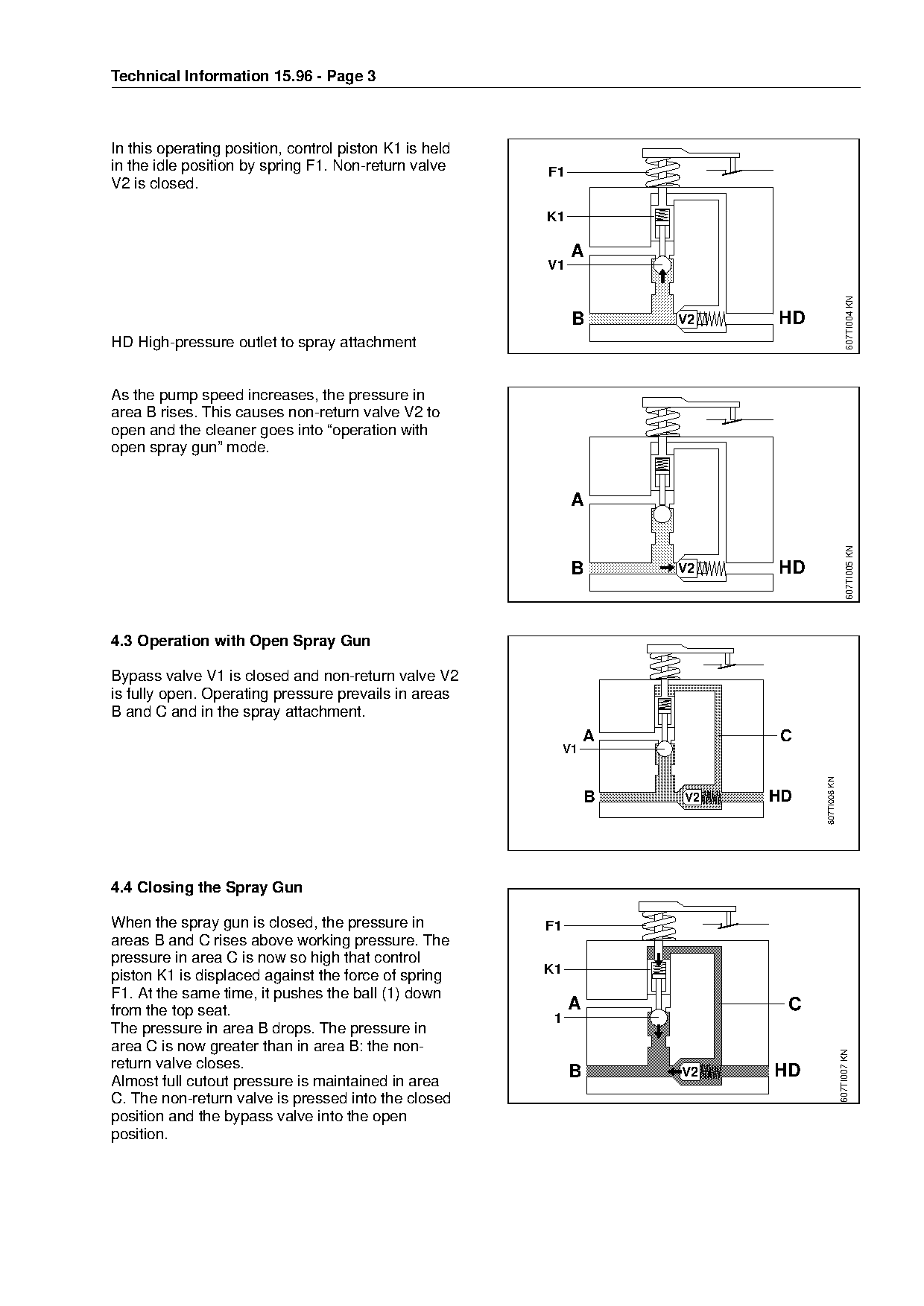
In this operating position, control piston K1 is held
in the idle position by spring F1. Non-return valve          F1
V2 is closed.


                                                                  A
                                                             V1

                                                                                                          607TI004 KN
                                                                  B         V2   HD
HD High-pressure outlet to spray attachment

As the pump speed increases, the pressure in
area B rises. This causes non-return valve V2 to
open and the cleaner goes into “operation with

open spray gun” mode.


                                                                                                         607TI005 KN
                                                                  B         V2   HD

4.3 Operation with Open Spray Gun

Bypass valve V1 is closed and non-return valve V2
is fully open. Operating pressure prevails in areas

B and C and in the spray attachment.

                                                                      A          C
                                                                 V1

                                                                                      607TI006 KN
                                                                      B     V2   HD

4.4 Closing the Spray Gun

When the spray gun is closed, the pressure in            F1
areas B and C rises above working pressure. The
pressure in area C is now so high that control

piston K1 is displaced against the force of spring       K1
F1. At the same time, it pushes the ball (1) down
from the top seat.                                                A               C
                                                             1
The pressure in area B drops. The pressure in
area C is now greater than in area B: the non-
                                                                                                    607TI007 KN

return valve closes.
                                                                  B         V2   HD
Almost full cutout pressure is maintained in area
C. The non-return valve is pressed into the closed
position and the bypass valve into the open
position.
Page 4 of 9
Text of page 4 — search, copy, screen readers
Technical Information 15.96 - Page 4

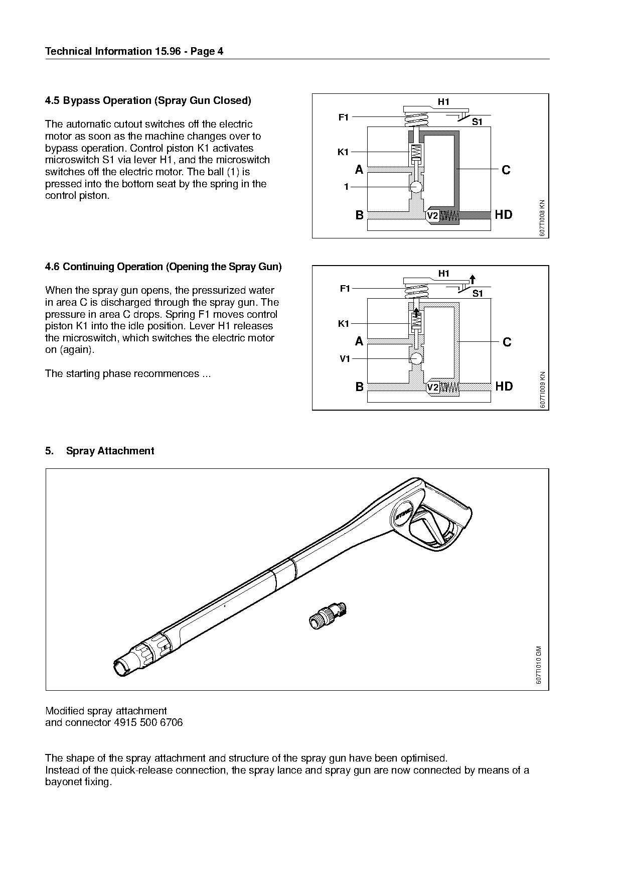
4.5 Bypass Operation (Spray Gun Closed)                                           H1
                                                             F1                           S1
The automatic cutout switches off the electric
motor as soon as the machine changes over to
bypass operation. Control piston K1 activates                K1
microswitch S1 via lever H1, and the microswitch
switches off the electric motor. The ball (1) is                   A                            C
pressed into the bottom seat by the spring in the              1
control piston.

                                                                                                                607TI008 KN
                                                                   B            V2             HD

4.6 Continuing Operation (Opening the Spray Gun)
                                                                                     H1
When the spray gun opens, the pressurized water               F1
                                                                                          S1

in area C is discharged through the spray gun. The
pressure in area C drops. Spring F1 moves control
piston K1 into the idle position. Lever H1 releases          K1

the microswitch, which switches the electric motor                 A                            C
on (again).
                                                             V1
The starting phase recommences ...                             fo

                                                                                                                607TI009 KN
                                                                   B            V2             HD

5.   Spray Attachment

                                                                                                         607TI010 GM

Modified spray attachment
and connector 4915 500 6706

The shape of the spray attachment and structure of the spray gun have been optimised.
Instead of the quick-release connection, the spray lance and spray gun are now connected by means of a
bayonet fixing.
Page 5 of 9
Text of page 5 — search, copy, screen readers
Technical Information 15.96 - Page 5

The washing brush supplied with the high-pressure
cleaner and the spray kit injector have been converted
to a bayonet fixing. Connector 4915 500 6706 is
also supplied with the cleaner.

Special accessories with the quick-release connection
can be connected to the spray gun using this
connector. The connector is identical to connector
4915 500 6700, supplied with the RE 101 K, the
only difference being that it is made of aluminium.

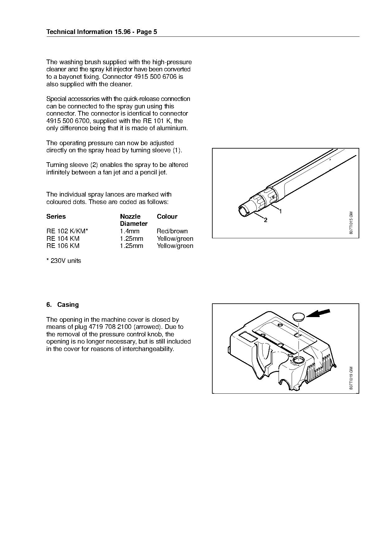
The operating pressure can now be adjusted
directly on the spray head by turning sleeve (1).

Turning sleeve (2) enables the spray to be altered
infinitely between a fan jet and a pencil jet.

The individual spray lances are marked with
coloured dots. These are coded as follows:


                                                                        607TI015 GM
Series                     Nozzle       Colour
                                                                2
                           Diameter
RE 102 K/KM*
RE 104 KM
                           1.4mm
                           1.25mm
                                        Red/brown
                                        Yellow/green
RE 106 KM                  1.25mm       Yellow/green

* 230V units

6. Casing

The opening in the machine cover is closed by
means of plug 4719 708 2100 (arrowed). Due to
the removal of the pressure control knob, the

opening is no longer necessary, but is still included
in the cover for reasons of interchangeability.

                                                                        607TI019 GM
Page 6 of 9
Text of page 6 — search, copy, screen readers
Technical Information 15.96 - Page 6

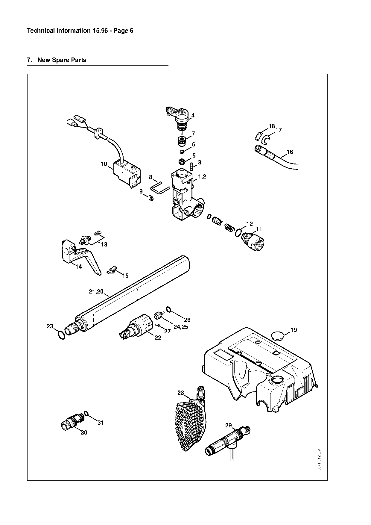
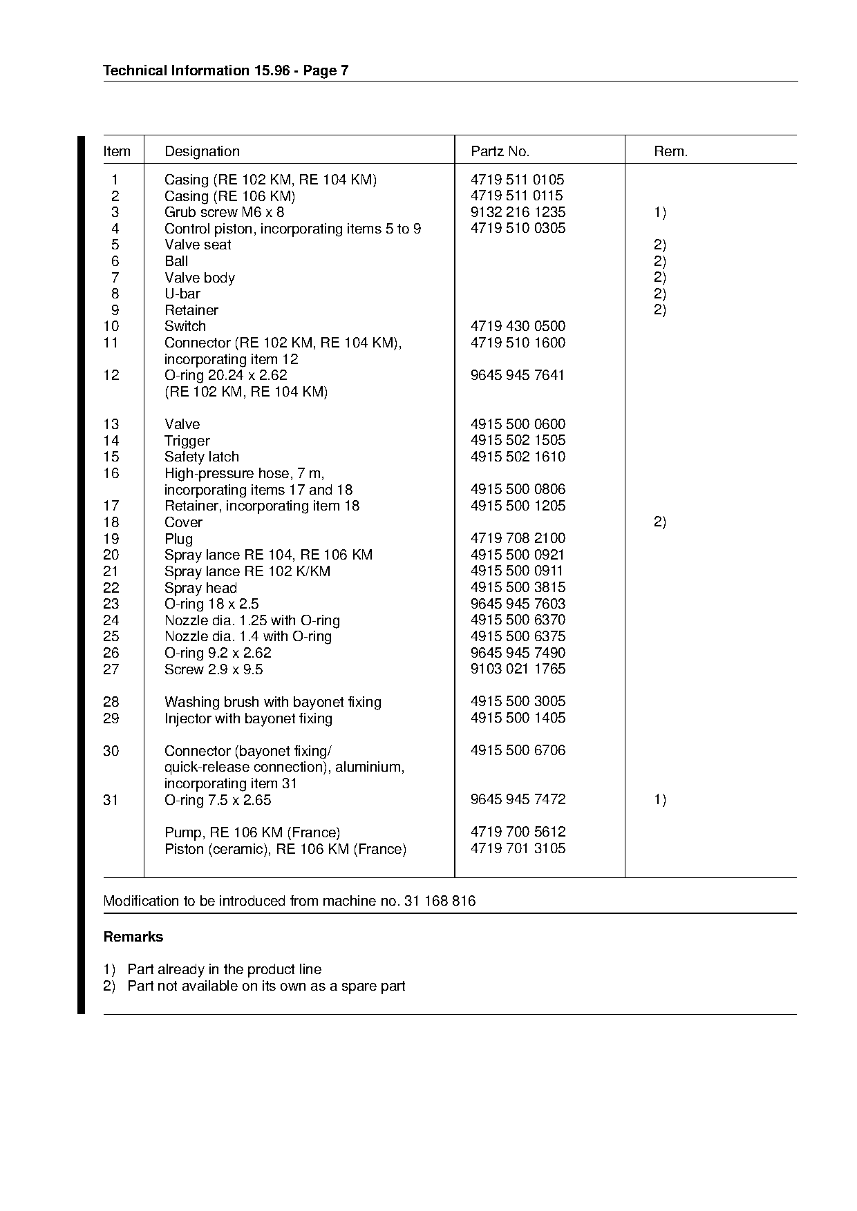
7. New Spare Parts

                                                                  4
                                                                                            18
                                                                                                 17
                                                                  7
                                                                  6


                                                                  5
                          10                                          3

                                           8                          1,2


                                                                            fo    12
                                                                                       11
                           13

                14
                                15

                       21,20


      23                                                 24,25
                                                    27                                                 19
                                               22


                         31                                                  29
                  30
                                                                                                            607TI012 GM
Page 7 of 9
Text of page 7 — search, copy, screen readers
Technical Information 15.96 - Page 7

Item      Designation                                   Partz No.          Rem.
 1        Casing (RE 102 KM, RE 104 KM)                 4719 511 0105
 2        Casing (RE 106 KM)                            4719 511 0115
 3        Grub screw M6 x 8                             9132 216 1235      1)
 4        Control piston, incorporating items 5 to 9    4719 510 0305
 5        Valve seat                                                       2)
 6        Ball                                                             2)
 7        Valve body                                                       2)
 8        U-bar                                                            2)
 9        Retainer                                                         2)
10        Switch                                        4719 430 0500

11        Connector (RE 102 KM, RE 104 KM),             4719 510 1600

          incorporating item 12
12        O-ring 20.24 x 2.62                           9645 945 7641
          (RE 102 KM, RE 104 KM)

13        Valve                                         4915 500 0600
14        Trigger                                       4915 502 1505

15        Safety latch                                  4915 502 1610
16        High-pressure hose, 7 m,
          incorporating items 17 and 18                 4915 500 0806
17
18
          Retainer, incorporating item 18
          Cover
                                                        4915 500 1205
                                                                           2)
19        Plug                                          4719 708 2100
20        Spray lance RE 104, RE 106 KM                 4915 500 0921
21        Spray lance RE 102 K/KM                       4915 500 0911
22        Spray head                                    4915 500 3815

23        O-ring 18 x 2.5                               9645 945 7603
24        Nozzle dia. 1.25 with O-ring                  4915 500 6370
25        Nozzle dia. 1.4 with O-ring                   4915 500 6375
26        O-ring 9.2 x 2.62                             9645 945 7490

27        Screw 2.9 x 9.5                               9103 021 1765

28        Washing brush with bayonet fixing             4915 500 3005
29        Injector with bayonet fixing                  4915 500 1405

30        Connector (bayonet fixing/                    4915 500 6706
          quick-release connection), aluminium,

          incorporating item 31
31        O-ring 7.5 x 2.65                             9645 945 7472      1)

          Pump, RE 106 KM (France)                      4719 700 5612

          Piston (ceramic), RE 106 KM (France)          4719 701 3105

Modification to be introduced from machine no. 31 168 816

Remarks

1) Part already in the product line
2) Part not available on its own as a spare part
Page 8 of 9
Text of page 8 — search, copy, screen readers
Technical Information 15.96 - Page 8

8. Valve Block - Pump Casing Screwed
   Connection

The tightening torque for brass valve blocks has
been increased to 15 Nm.
The tightening torque for aluminium valve blocks is
still 10 Nm.

9. Service Notes

If the high-pressure cleaner is started up during

 repair or maintenance work, the safety regulations

applicable in the country of use and the safety
instructions in the Owner’s Manual must be
followed.

9.1 Adjusting the Pressure Control

The pressure control is adjusted as described in
the service instructions. The rotary knob is no
longer present.

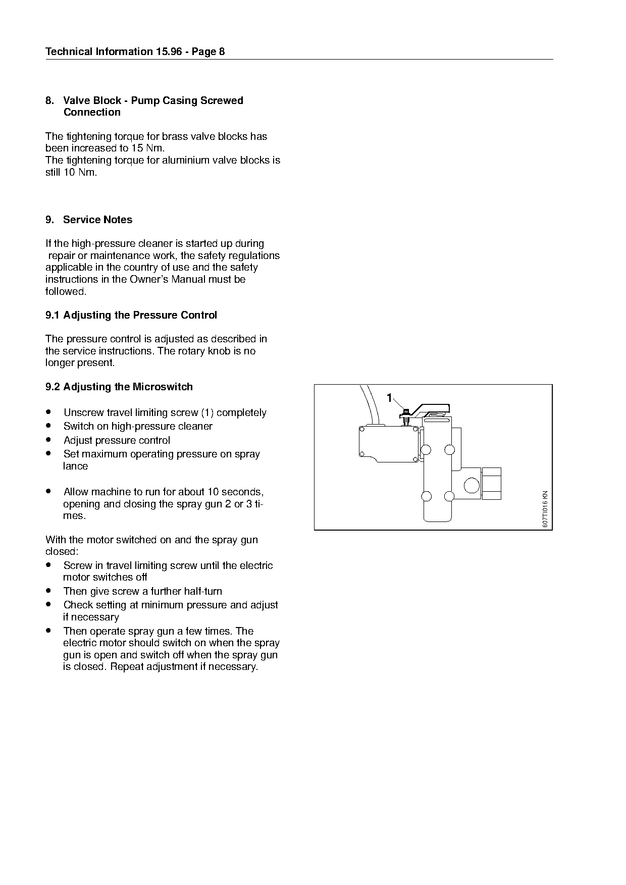
9.2 Adjusting the Microswitch
                                                            1
•   Unscrew travel limiting screw (1) completely
•   Switch on high-pressure cleaner

•   Adjust pressure control
•   Set maximum operating pressure on spray
    lance

• Allow machine to run for about 10 seconds,

                                                                        607TI016 KN

    opening and closing the spray gun 2 or 3 ti-
    mes.

With the motor switched on and the spray gun

closed:
• Screw in travel limiting screw until the electric

    motor switches off
• Then give screw a further half-turn
• Check setting at minimum pressure and adjust

    if necessary
• Then operate spray gun a few times. The
    electric motor should switch on when the spray

    gun is open and switch off when the spray gun
    is closed. Repeat adjustment if necessary.
Page 9 of 9
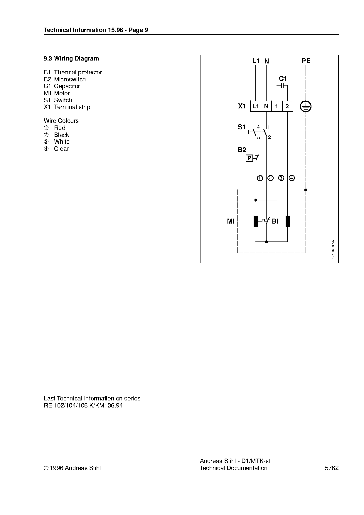
Text of page 9 — search, copy, screen readers
Technical Information 15.96 - Page 9

9.3 Wiring Diagram                                                  L1 N                        PE
B1 Thermal protector
B2 Microswitch                                                                      C1
C1 Capacitor
M1 Motor
S1 Switch
X1 Terminal strip                                          X1 L1 N             1        2

Wire Colours
➀ Red                                                      S1        4   1
➁ Black                                                              5   2
➂ White

➃ Clear


                                                                     1     2        3       4

                                              fo      MI                       BI

                                                                                                      607TI018 KN

Last Technical Information on series
RE 102/104/106 K/KM: 36.94

                                             Andreas Stihl - D1/MTK-st
ñ 1996 Andreas Stihl                         Technical Documentation                                 5762
Most of these PDFs embed fonts with a shifted character map, so the text above was recovered rather than copied — read it as a faithful but imperfect transcription, and treat the page image above each block as the authority where the two disagree — the figures exist only there, because they are vector drawings that text extraction cannot keep.