Technical Information · issue 26 of 1996
Air filter system and compensator; HS 277 carburet
IssueTI 26/1996
From serial 24 073 218, 24 093 969
Part changes (2)
| Was | Becomes | What the bulletin says |
|---|---|---|
| 4205 400 1000 | 4205 400 1001 | X 24 097 471=the original trigger unit 4205 400 1000 is replaced by the new version 4205 400 1001. |
| 4201 007 1026 | 4201 007 1041 | 6.2=Cutting depth limiter assembly=fn connection with the introduction of 400 mm (16") cutting wheels the original cutting depth limiter assembly 4201 007 1026 is replaced by the new version 4201 007 1041. |
Full text
Page 1 of 14
Text of page 1 — search, copy, screen readers
Technical Information

                                                                                                    26.96

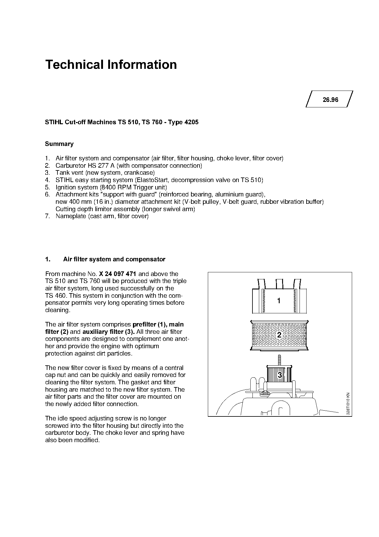
STIHL Cut-off Machines TS 510, TS 760 - Type 4205

6XPPDU\

1. Air filter system and compensator (air filter, filter housing, choke lever, filter cover)
2. Carburetor HS 277 A (with compensator connection)
3. Tank vent (new system, crankcase)
4. STIHL easy starting system (ElastoStart, decompression valve on TS 510)

5. Ignition system (8400 RPM Trigger unit)
6. Attachment kits "support with guard" (reinforced bearing, aluminium guard),
   new 400 mm (16 in.) diameter attachment kit (V-belt pulley, V-belt guard, rubber vibration buffer)

   Cutting depth limiter assembly (longer swivel arm)
7. Nameplate (cast arm, filter cover)

1.=====Air filter system and compensator

From machine NoK=X 24 097 471 ~nd above the
TS 510 and TS 760 will be produced with the triple
air filter system, long used successfully on the

TS 460. This system in conjunction with the com-
                                                                                   1

pensator permits very long operating times before
cleaning.

The air filter system comprises prefilter =1=, main

filter =2=~nd auxiliary filter =3=.=^ll three air filter
components are designed to complement one anot-
                                                                                    2
her and provide the engine with optimum

protection against dirt particles.

The new filter cover is fixed by means of a central

cap nut and can be quickly and easily removed for                                   3
cleaning the filter system. The gasket and filter
housing are matched to the new filter system. The

                                                                                                            328TI010 KN

air filter parts and the filter cover are mounted on
the newly added filter connection.

The idle speed adjusting screw is no longer
screwed into the filter housing but directly into the
carburetor body. The choke lever and spring have
also been modified.
Page 2 of 14
Text of page 2 — search, copy, screen readers
Technical Information 26.96 - Page 2

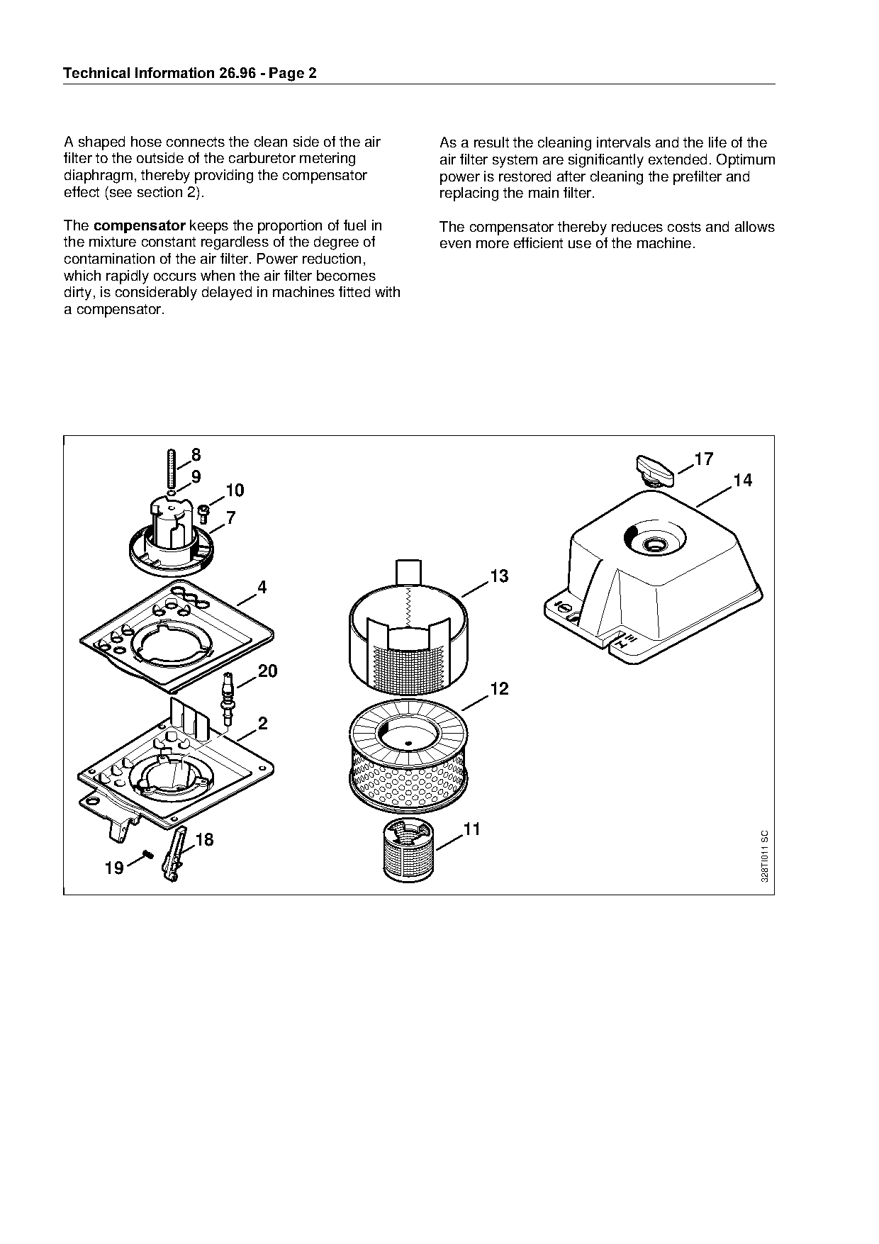
A shaped hose connects the clean side of the air         As a result the cleaning intervals and the life of the
filter to the outside of the carburetor metering         air filter system are significantly extended. Optimum
diaphragm, thereby providing the compensator             power is restored after cleaning the prefilter and
effect (see section 2).                                  replacing the main filter.

The FRPSHQVDWRU keeps the proportion of fuel in          The compensator thereby reduces costs and allows
the mixture constant regardless of the degree of         even more efficient use of the machine.
contamination of the air filter. Power reduction,
which rapidly occurs when the air filter becomes
dirty, is considerably delayed in machines fitted with
a compensator.

                    8                                                                            17

                    9                                                                                   14
                         10
                         7                                       fo
                                                                 13
                              4


                                                            11
                                                                                                             328TI011 SC


      19
Page 3 of 14
Text of page 3 — search, copy, screen readers
Technical Information 26.96 - Page 3

6XPPDU\

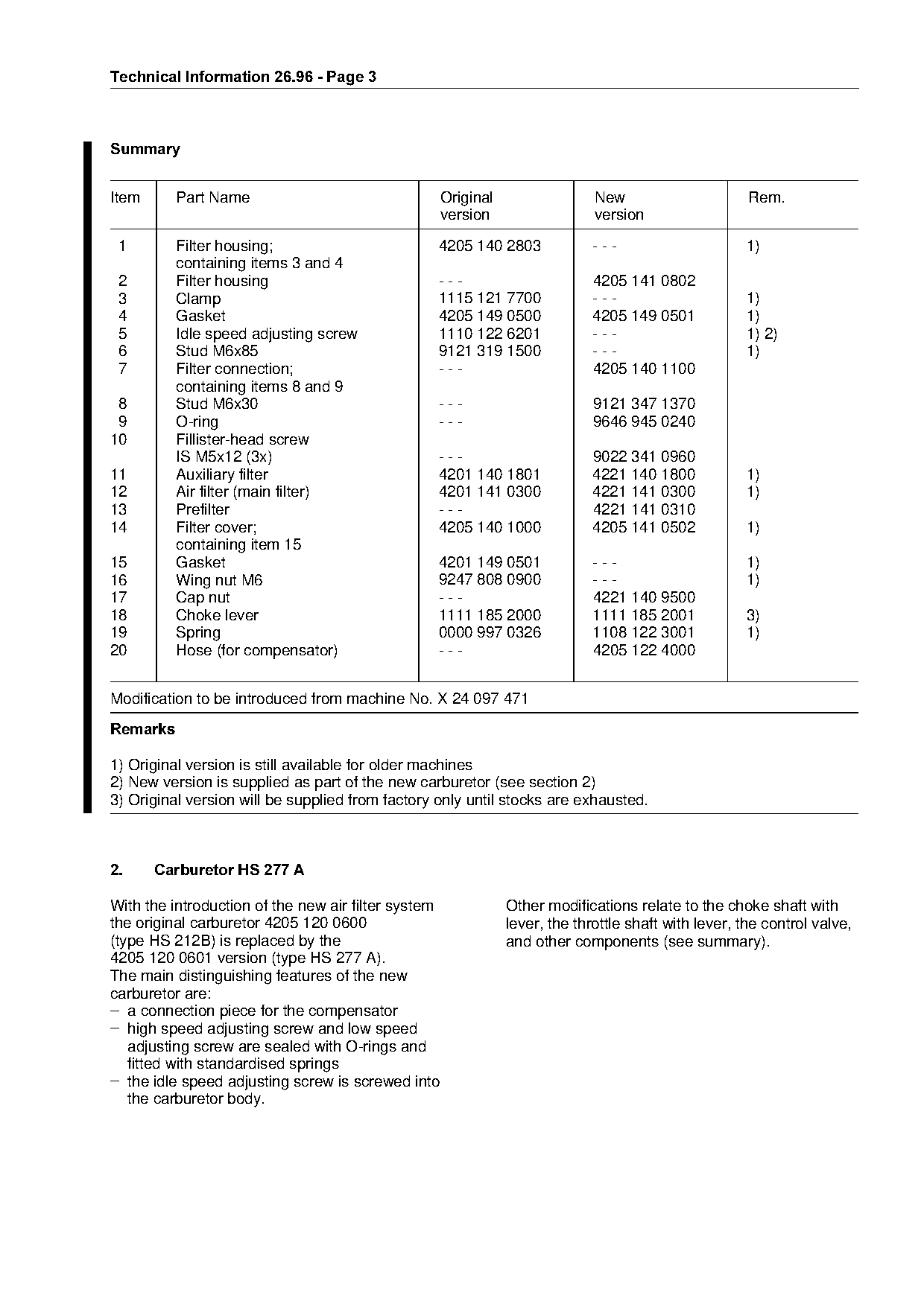
Item      Part Name                                  Original                 New                      Rem.
                                                     version                  version
 1        Filter housing;                         4205 140 2803               ---                     1)
          containing items 3 and 4
 2        Filter housing                          ---                         4205 141 0802
 3        Clamp                                   1115 121 7700               ---                     1)
 4        Gasket                                  4205 149 0500               4205 149 0501           1)
 5        Idle speed adjusting screw              1110 122 6201               ---                     1) 2)
 6        Stud M6x85                              9121 319 1500               ---                     1)

 7        Filter connection;                      ---                         4205 140 1100

          containing items 8 and 9
 8        Stud M6x30                              ---                         9121 347 1370
 9        O-ring                                  ---                         9646 945 0240

10        Fillister-head screw
          IS M5x12 (3x)                           ---                         9022 341 0960
11        Auxiliary filter                        4201 140 1801               4221 140 1800           1)
12        Air filter (main filter)                4201 141 0300               4221 141 0300           1)

13        Prefilter                               ---                         4221 141 0310
14        Filter cover;                           4205 140 1000               4205 141 0502           1)

15
          containing item 15
          Gasket                                  4201 149 0501
                                                                 fo           ---                     1)
16        Wing nut M6                             9247 808 0900               ---                     1)
17        Cap nut                                 ---                         4221 140 9500
18        Choke lever                             1111 185 2000               1111 185 2001           3)
19        Spring                                  0000 997 0326               1108 122 3001           1)

20        Hose (for compensator)                  ---                         4205 122 4000

Modification to be introduced from machine No. X 24 097 471

5HPDUNV

1) Original version is still available for older machines
2) New version is supplied as part of the new carburetor (see section 2)
3) Original version will be supplied from factory only until stocks are exhausted.

2.=====Carburetor HS 277 A

With the introduction of the new air filter system              Other modifications relate to the choke shaft with

the original carburetor 4205 120 0600                           lever, the throttle shaft with lever, the control valve,
(type HS 212B) is replaced by the                               and other components (see summary).
4205 120 0601 version (type HS 277 A).

The main distinguishing features of the new
carburetor are:
– a connection piece for the compensator
– high speed adjusting screw and low speed
   adjusting screw are sealed with O-rings and
   fitted with standardised springs
– the idle speed adjusting screw is screwed into
   the carburetor body.
Page 4 of 14
Text of page 4 — search, copy, screen readers
Technical Information 26.96 - Page 4

2.1=Setting the carburetor

From machine No. X 24 073 218 onward, the
speed on the TS 510/760 is no longer limited via
the control valve in the carburetor but via the
ignition system (see TI 33.95, "Electronic speed
limiting?FK The maximum speed can therefore
not be increased beyond a maximum design
value when adjusting the carburetor.

Standard setting

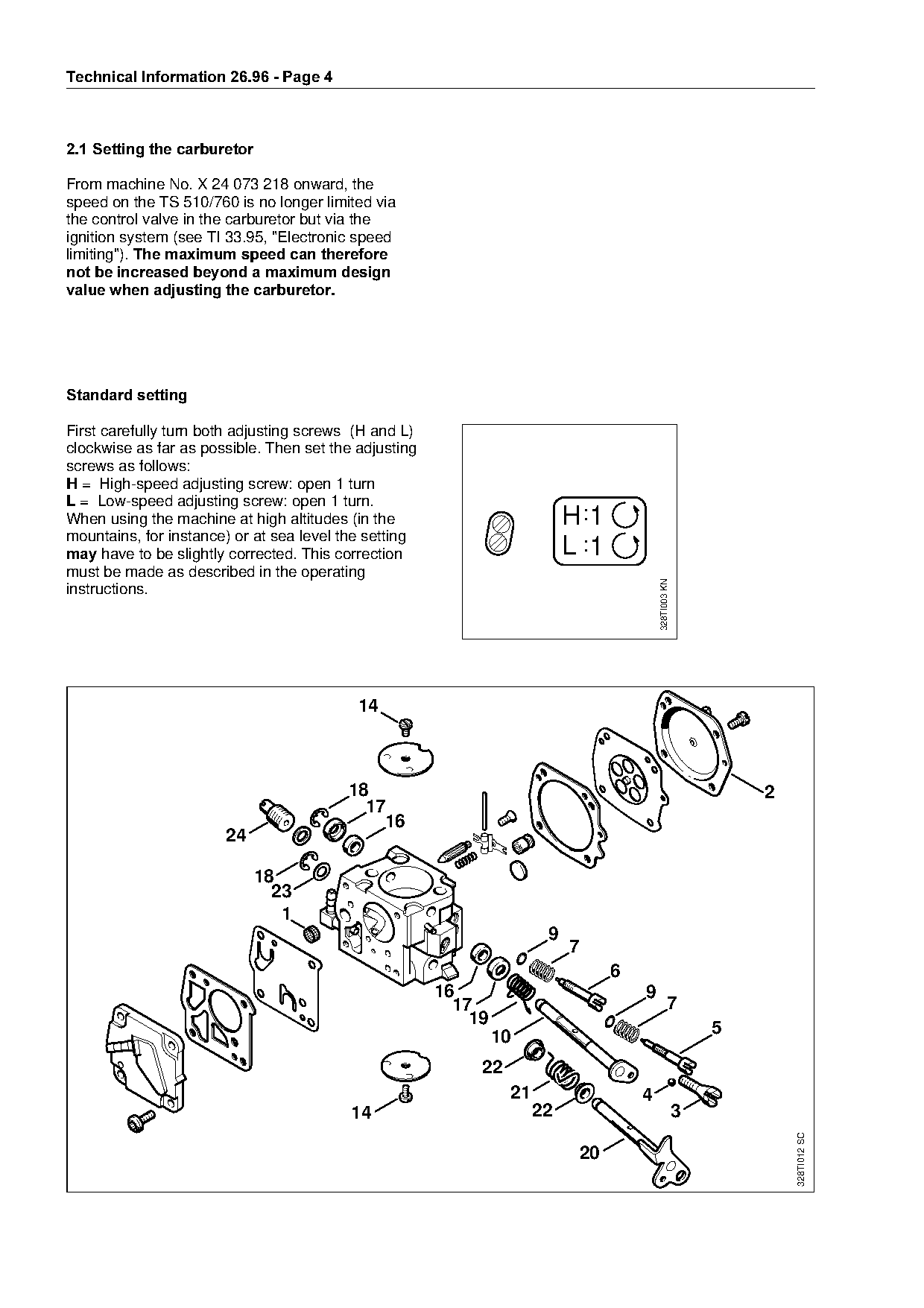
First carefully turn both adjusting screws (H and L)

clockwise as far as possible. Then set the adjusting
screws as follows:
+ = High-speed adjusting screw: open 1 turn

/ = Low-speed adjusting screw: open 1 turn.
When using the machine at high altitudes (in the                           H :1
mountains, for instance) or at sea level the setting
PD\ have to be slightly corrected. This correction
must be made as described in the operating
                                                                     fo    L :1

                                                                                          328TI003 KN
instructions.


                                         18                                                                     2

                                           17
                                             16
                       24

                             18
                               23

                                1
                                                                       9
                                                                           7

                                                                                  6
                                                       16                             9
                                                         17                                       7
                                                           19
                                                                10                                          5

                                                            22
                                                                 21                   4
                                          14                          22                                3
                                                                                                                    328TI012 SC

                                                                            20
Page 5 of 14
Text of page 5 — search, copy, screen readers
Technical Information 26.96 - Page 5

6XPPDU\

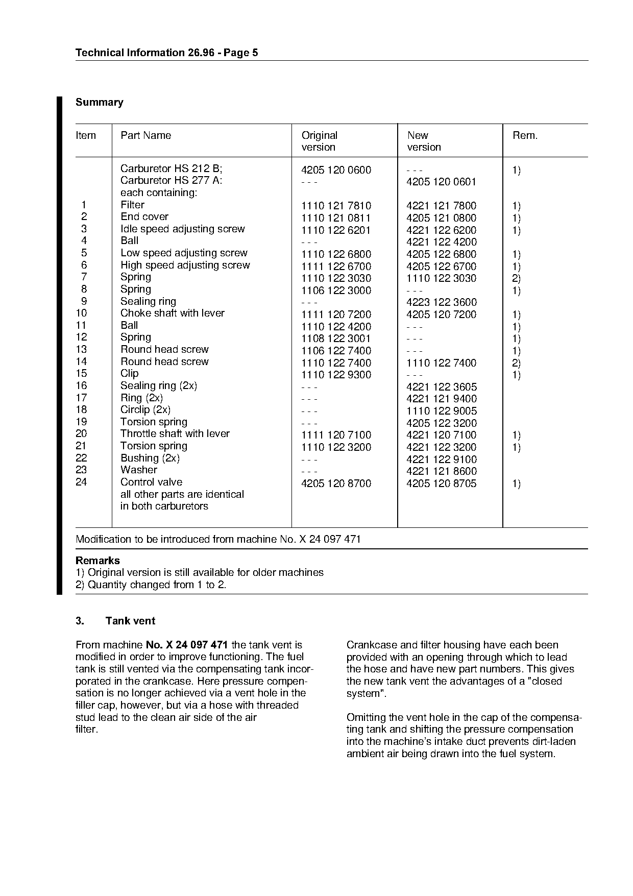
Item      Part Name                                Original               New                    Rem.
                                                   version                version
          Carburetor HS 212 B;                     4205 120 0600          ---                    1)
          Carburetor HS 277 A:                     ---                    4205 120 0601
          each containing:
 1        Filter                                   1110 121 7810          4221 121 7800         1)
 2        End cover                                1110 121 0811          4205 121 0800         1)
 3        Idle speed adjusting screw               1110 122 6201          4221 122 6200         1)
 4        Ball                                     ---                    4221 122 4200

 5        Low speed adjusting screw                1110 122 6800          4205 122 6800         1)

 6        High speed adjusting screw               1111 122 6700          4205 122 6700         1)
 7        Spring                                   1110 122 3030          1110 122 3030         2)
 8        Spring                                   1106 122 3000          ---                   1)

 9        Sealing ring                             ---                    4223 122 3600
10        Choke shaft with lever                   1111 120 7200          4205 120 7200         1)
11        Ball                                     1110 122 4200          ---                   1)
12        Spring

                                                   1108 122 3001          ---                   1)
13        Round head screw                         1106 122 7400          ---                   1)
14        Round head screw                         1110 122 7400          1110 122 7400         2)
15
16
          Clip
          Sealing ring (2x)                        ---
                                                   1110 122 9300          ---
                                                                          4221 122 3605
                                                                                                1)

17        Ring (2x)                                ---                    4221 121 9400
18        Circlip (2x)                             ---                    1110 122 9005
19        Torsion spring                           ---                    4205 122 3200
20        Throttle shaft with lever                1111 120 7100          4221 120 7100         1)

21        Torsion spring                           1110 122 3200          4221 122 3200         1)
22        Bushing (2x)                             ---                    4221 122 9100
23        Washer                                   ---                    4221 121 8600
24        Control valve                            4205 120 8700          4205 120 8705         1)

          all other parts are identical

          in both carburetors

Modification to be introduced from machine No. X 24 097 471

5HPDUNV
1) Original version is still available for older machines

2) Quantity changed from 1 to 2.

3.=====Tank vent

From machine No. X 24 097 471=the tank vent is                Crankcase and filter housing have each been
modified in order to improve functioning. The fuel            provided with an opening through which to lead

tank is still vented via the compensating tank incor-         the hose and have new part numbers. This gives
porated in the crankcase. Here pressure compen-               the new tank vent the advantages of a "closed
sation is no longer achieved via a vent hole in the           system".
filler cap, however, but via a hose with threaded
stud lead to the clean air side of the air                    Omitting the vent hole in the cap of the compensa-
filter.                                                       ting tank and shifting the pressure compensation
                                                              into the machine’s intake duct prevents dirt-laden
                                                              ambient air being drawn into the fuel system.
Page 6 of 14
Text of page 6 — search, copy, screen readers
Technical Information 26.96 - Page 6

3.1===Supply of spare parts

Machines with original tank vent

In the case of machines with original tank venting
the grey filler cap 4205 007 1061 (with vent hole
and threaded stud) must be used for the compensa-
ting tank in order to ensure the venting function.

Machines with new tank vent system

For the compensating tank of machines with new
tank vent system the new filler cap 4205 350 0550

must be used. This filler cap has no vent hole and is

colored RUDQJH for identification purposes.

3.2===Service notes

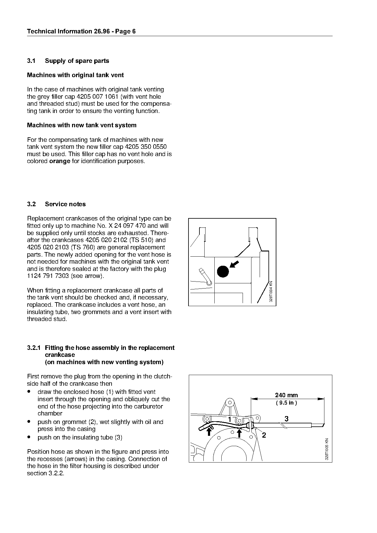
Replacement crankcases of the original type can be
fitted only up to machine No. X 24 097 470 and will
be supplied only until stocks are exhausted. There-
after the crankcases 4205 020 2102 (TS 510) and
4205 020 2103 (TS 760) are general replacement
parts. The newly added opening for the vent hose is

not needed for machines with the original tank vent
and is therefore sealed at the factory with the plug
1124 791 7303 (see arrow).
                                                                        328TI004 KN

When fitting a replacement crankcase all parts of
the tank vent should be checked and, if necessary,

replaced. The crankcase includes a vent hose, an
insulating tube, two grommets and a vent insert with
threaded stud.

3.2.1=Fitting the hose assembly in the replacement
      FUDQNFDVH
=======on machines with new venting system

First remove the plug from the opening in the clutch-
side half of the crankcase then
• draw the enclosed hose (1) with fitted vent

                                                                                      240 mm
    insert through the opening and obliquely cut the
                                                                                      ( 9.5 in )
    end of the hose projecting into the carburetor
    chamber
• push on grommet (2), wet slightly with oil and              1                           3
    press into the casing
• push on the insulating tube (3)                                   2
                                                                                                   328TI005 KN

Position hose as shown in the figure and press into
the recesses (arrows) in the casing. Connection of
the hose in the filter housing is described under
section 3.2.2.
Page 7 of 14
Text of page 7 — search, copy, screen readers
Technical Information 26.96 - Page 7

3.2.2=Replacing a defective hose
=======on machines with new
      tank venting system

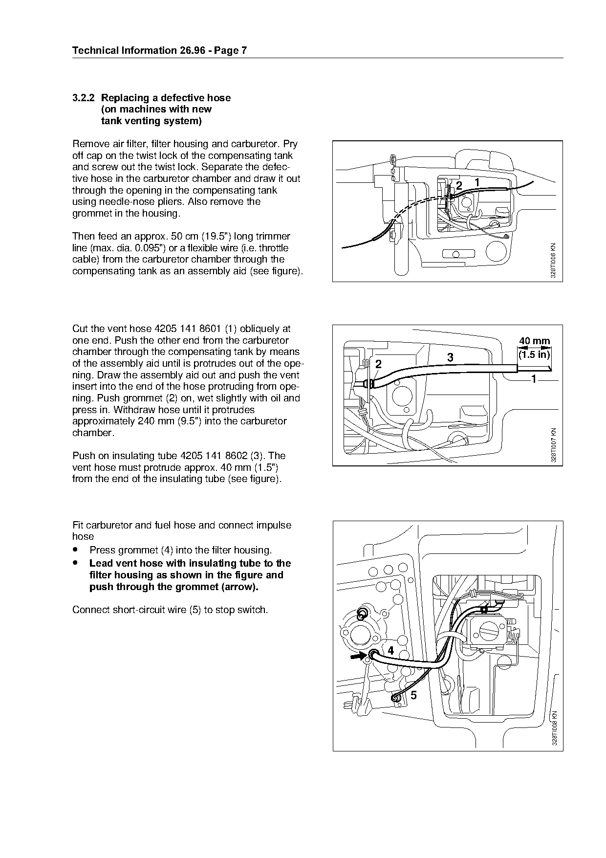
Remove air filter, filter housing and carburetor. Pry
off cap on the twist lock of the compensating tank
and screw out the twist lock. Separate the defec-
tive hose in the carburetor chamber and draw it out
through the opening in the compensating tank                                     2 1
using needle-nose pliers. Also remove the
grommet in the housing.

Then feed an approx. 50 cm (19.5") long trimmer

                                                                                                  328TI006 KN
line (max. dia. 0.095") or a flexible wire (i.e. throttle

cable) from the carburetor chamber through the
compensating tank as an assembly aid (see figure).

Cut the vent hose 4205 141 8601 (1) obliquely at
one end. Push the other end from the carburetor                                        40 mm
chamber through the compensating tank by means                                         (1.5 in)
of the assembly aid until is protrudes out of the ope-
ning. Draw the assembly aid out and push the vent
                                                             fo  2
                                                                             3
                                                                                          1
insert into the end of the hose protruding from ope-
ning. Push grommet (2) on, wet slightly with oil and
press in. Withdraw hose until it protrudes

approximately 240 mm (9.5") into the carburetor

                                                                                                  328TI007 KN
chamber.

Push on insulating tube 4205 141 8602 (3). The

vent hose must protrude approx. 40 mm (1.5")
from the end of the insulating tube (see figure).

Fit carburetor and fuel hose and connect impulse

hose
• Press grommet (4) into the filter housing.

•=Lead vent hose with insulating tube to the
=====filter housing as shown in the figure and
=====push through the grommet =arrow=.

Connect short-circuit wire (5) to stop switch.


                                                                         5
                                                                                                     328TI008 KN
Page 8 of 14
Text of page 8 — search, copy, screen readers
Technical Information 26.96 - Page 8

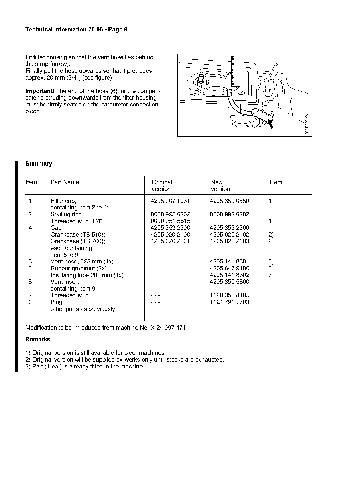
Fit filter housing so that the vent hose lies behind
the strap (arrow).
Finally pull the hose upwards so that it protrudes
approx. 20 mm (3/4") (see figure).
                                                                      6
Important!=qhe end of the hose (6) for the compen-
sator protruding downwards from the filter housing
must be firmly seated on the carburetor connection
piece.

                                                                                                 328TI009 KN
6XPPDU\

Item      Part Name                                Original               New             Rem.
                                                   version                version

 1        Filler cap;                             4205 007 1061           4205 350 0550   1)

 2
 3
          containing item 2 to 4;
          Sealing ring
          Threaded stud, 1/4"
                                                  0000 992 6302
                                                  0000 951 5815
                                                                   fo     0000 992 6302
                                                                          ---             1)
 4        Cap                                     4205 353 2300           4205 353 2300
          Crankcase (TS 510);                     4205 020 2100           4205 020 2102   2)
          Crankcase (TS 760);                     4205 020 2101           4205 020 2103   2)

          each containing
          item 5 to 9;
 5        Vent hose, 325 mm (1x)                  ---                     4205 141 8601   3)
 6        Rubber grommet (2x)                     ---                     4205 647 9100   3)

 7        Insulating tube 200 mm (1x)             ---                     4205 141 8602   3)
 8        Vent insert;                            ---                     4205 350 5800

          containing item 9;
 9        Threaded stud                           ---                     1120 358 8105
10        Plug                                    ---                     1124 791 7303

          other parts as previously

Modification to be introduced from machine No. X 24 097 471

5HPDUNV

1) Original version is still available for older machines
2) Original version will be supplied ex-works only until stocks are exhausted.
3) Part (1 ea.) is already fitted in the machine.
Page 9 of 14
Text of page 9 — search, copy, screen readers
Technical Information 26.96 - Page

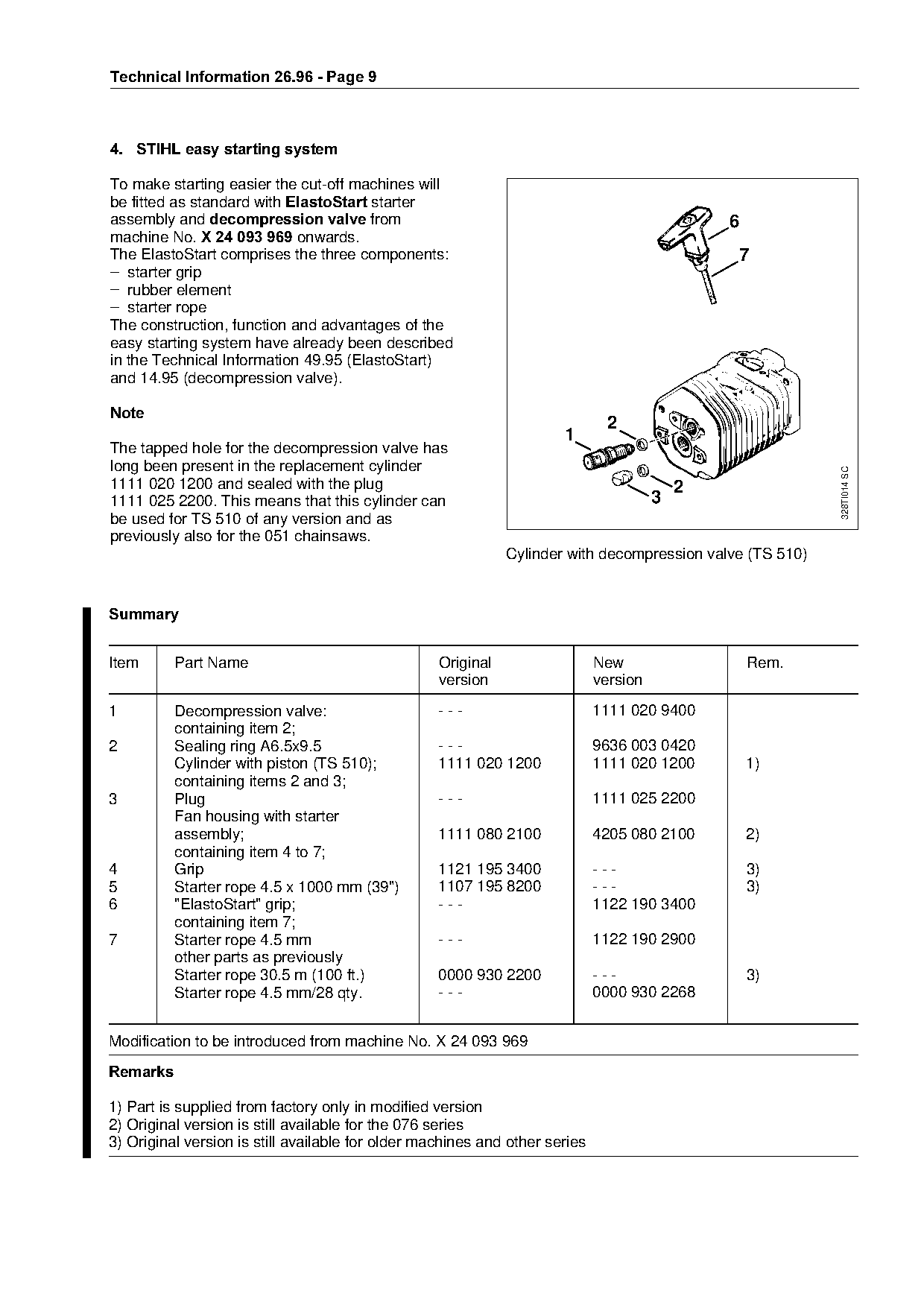
4.=STIHL easy starting system

To make starting easier the cut-off machines will
be fitted as standard with (ODVWR6WDUW starter
assembly and decompression valve=from                                                          6
machine NoK=X 24 093 969 onwards.
The ElastoStart comprises the three components:                                                7
– starter grip
– rubber element
– starter rope
The construction, function and advantages of the
easy starting system have already been described
in the Technical Information 49.95 (ElastoStart)

and 14.95 (decompression valve).

1RWH
                                                                              2
                                                                      1

The tapped hole for the decompression valve has
long been present in the replacement cylinder

                                                                                                           328TI014 SC
1111 020 1200 and sealed with the plug                                                     2

1111 025 2200. This means that this cylinder can                                       3
be used for TS 510 of any version and as
previously also for the 051 chainsaws.
                                                              Cylinder with decompression valve (TS 510)
6XPPDU\

Item      Part Name                                Original                  New                   Rem.
                                                   version                   version

1         Decompression valve:                     ---                       1111 020 9400
          containing item 2;

2         Sealing ring A6.5x9.5                    ---                       9636 003 0420
          Cylinder with piston (TS 510);           1111 020 1200             1111 020 1200         1)
          containing items 2 and 3;
3         Plug                                     ---                       1111 025 2200

          Fan housing with starter
          assembly;                                1111 080 2100             4205 080 2100         2)

          containing item 4 to 7;
4         Grip                                     1121 195 3400             ---                   3)
5         Starter rope 4.5 x 1000 mm (39")         1107 195 8200             ---                   3)
6         "ElastoStart" grip;                      ---                       1122 190 3400

          containing item 7;
7         Starter rope 4.5 mm                      ---                       1122 190 2900
          other parts as previously

          Starter rope 30.5 m (100 ft.)            0000 930 2200             ---                   3)
          Starter rope 4.5 mm/28 qty.              ---                       0000 930 2268

Modification to be introduced from machine No. X 24 093 969
5HPDUNV

1) Part is supplied from factory only in modified version
2) Original version is still available for the 076 series
3) Original version is still available for older machines and other series
Page 10 of 14
Text of page 10 — search, copy, screen readers
Technical Information 26.96 - Page 10

5.=Ignition system

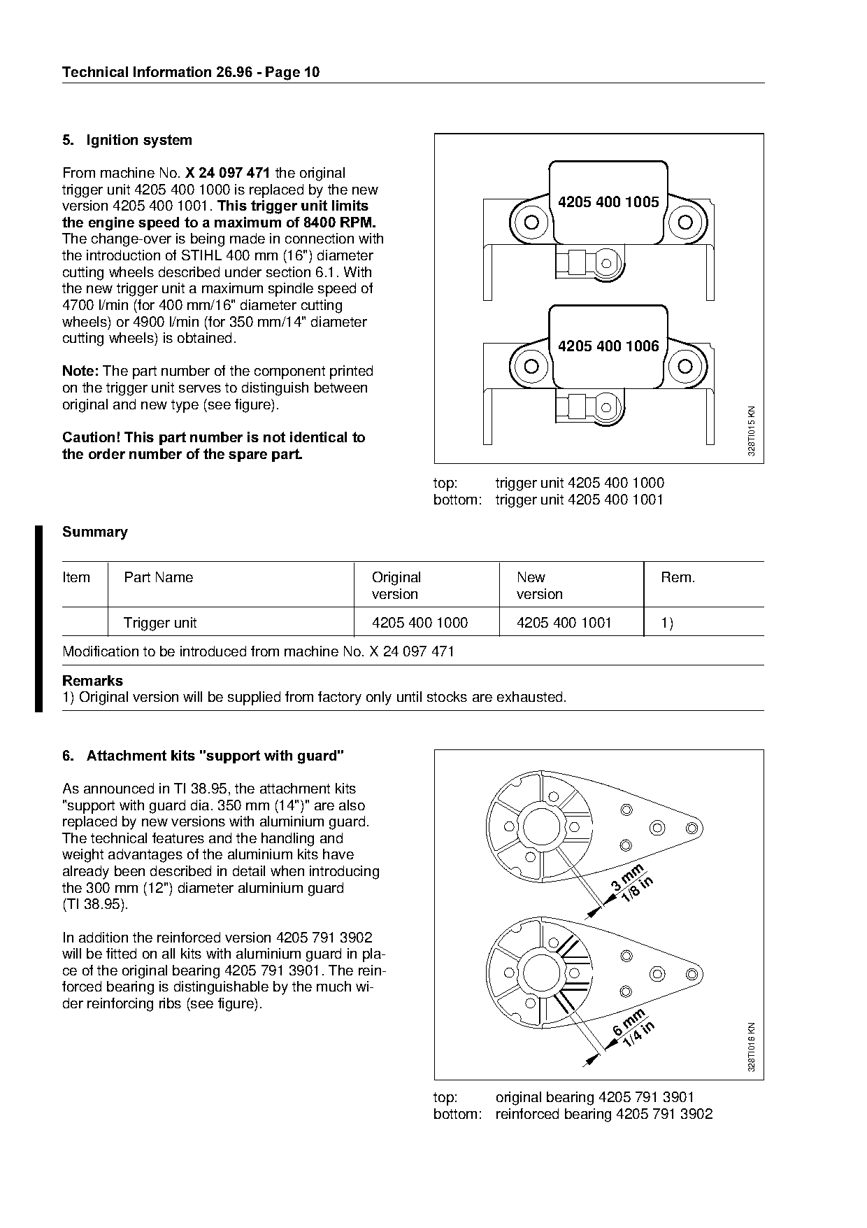
From machine NoK=X 24 097 471=the original
trigger unit 4205 400 1000 is replaced by the new
version=QOMR=QMM=NMMNK=This trigger unit limits==================================QOMR=QMM=NMMR
the engine speed to a maximum of 8400 RPM.
The change-over is being made in connection with
the introduction of STIHL 400 mm (16") diameter
cutting wheels described under section 6.1. With
the new trigger unit a maximum spindle speed of
4700 l/min (for 400 mm/16" diameter cutting
wheels) or 4900 l/min (for 350 mm/14" diameter
cutting wheels) is obtained.

                                                                                 4205 400 1006

Note:=qhe part number of the component printed
on the trigger unit serves to distinguish between
original and new type (see figure).

                                                                                                           328TI015 KN
Caution! This part number is not identical to
the order number of the spare part.

                                                               top:    trigger unit 4205 400 1000
                                                               bottom: trigger unit 4205 400 1001

6XPPDU\
Item      Part Name                                 Original               New                      Rem.
                                                    version                version

          Trigger unit                              4205 400 1000          4205 400 1001            1)
Modification to be introduced from machine No. X 24 097 471

5HPDUNV

1) Original version will be supplied from factory only until stocks are exhausted.

6.=Attachment kits "support with guard"

As announced in TI 38.95, the attachment kits

"support with guard dia. 350 mm (14")" are also
replaced by new versions with aluminium guard.
The technical features and the handling and

weight advantages of the aluminium kits have
already been described in detail when introducing                                              m
                                                                                            m
the 300 mm (12") diameter aluminium guard                                                  3 8 in
                                                                                            1/

(TI 38.95).

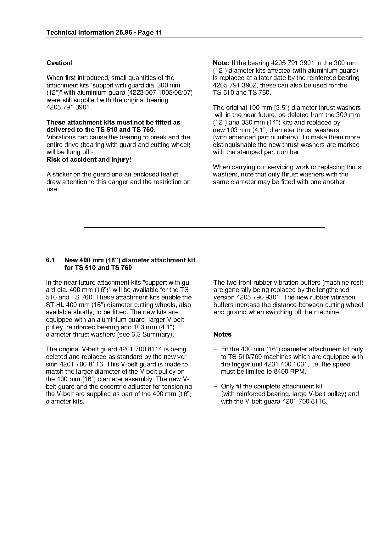
In addition the reinforced version 4205 791 3902
will be fitted on all kits with aluminium guard in pla-
ce of the original bearing 4205 791 3901. The rein-
forced bearing is distinguishable by the much wi-
der reinforcing ribs (see figure).
                                                                                              m
                                                                                            m
                                                                                           6 4 in
                                                                                                           328TI016 KN

                                                                                            1/

                                                               top:    original bearing 4205 791 3901
                                                               bottom: reinforced bearing 4205 791 3902
Page 11 of 14
Text of page 11 — search, copy, screen readers
Technical Information 26.96 - Page 11

Caution!===============================================Note: ff=the=be~ring=QOMR=TVN=PVMN=in=the=PMM=mm
                                                       (12") diameter kits affected (with aluminium guard)
When first introduced, small quantities of the         is replaced at a later date by the reinforced bearing
attachment kits "support with guard dia. 300 mm        4205 791 3902, these can also be used for the
(12")" with aluminium guard (4223 007 1005/06/07)      TS 510 and TS 760.
were still supplied with the original bearing
4205 791 3901.                                         The original 100 mm (3.9") diameter thrust washers,
                                                        will in the near future, be deleted from the 300 mm
These attachment kits must not be fitted as============ENO?F=~nd 350 mm (14") kits and replaced by
delivered to the TS 510 and TS 760. ===================new=NMP=mm=EQKN?F=di~meter=thrust=w~shers
Vibrations can cause the bearing to break and the      (with amended part numbers). To make them more
entire drive (bearing with guard and cutting wheel)    distinguishable the new thrust washers are marked
will be flung off -                                    with the stamped part number.

Risk of accident and injury!

                                                       When carrying out servicing work or replacing thrust
A sticker on the guard and an enclosed leaflet         washers, note that only thrust washers with the
draw attention to this danger and the restriction on   same diameter may be fitted with one another.

use.

6.1===New 400 mm =16"= diameter attachment kit
======for TS 510 and TS 760

In the near future attachment kits "support with gu-   The two front rubber vibration buffers (machine rest)
ard dia. 400 mm (16")" will be available for the TS    are generally being replaced by the lengthened
510 and TS 760. These attachment kits enable the       version 4205 790 9301. The new rubber vibration

STIHL 400 mm (16") diameter cutting wheels, also       buffers increase the distance between cutting wheel

available shortly, to be fitted. The new kits are      and ground when switching off the machine.
equipped with an aluminium guard, larger V-belt
pulley, reinforced bearing and 103 mm (4.1")
diameter thrust washers (see 6.3 Summary).             1RWHV

The original V-belt guard 4201 700 8114 is being       – Fit the 400 mm (16") diameter attachment kit only

deleted and replaced as standard by the new ver-         to TS 510/760 machines which are equipped with
sion 4201 700 8116. This V-belt guard is made to         the trigger unit 4201 400 1001, i.e. the speed
match the larger diameter of the V-belt pulley on        must be limited to 8400 RPM.
the 400 mm (16") diameter assembly. The new V-

belt guard and the eccentric adjuster for tensioning   – Only fit the complete attachment kit
the V-belt are supplied as part of the 400 mm (16")      (with reinforced bearing, large V-belt pulley) and
diameter kits.                                           with the V-belt guard 4201 700 8116.
Page 12 of 14
Text of page 12 — search, copy, screen readers
Technical Information 26.96 - Page 12

Summary of the attachment kits "support with guard"

Diameter===========Part nummer=========Guard===========Use======================Version /===============Rem.
guard===========================================================================Special features
300 mm (12")       4223 007 1006       Aluminium       for all TS series       with adjustment limit    1)
300 mm (12")       4223 007 1007       Aluminium       for all TS series       with water attachment    2)
350 mm (14")       4221 007 1006       Aluminium       for all TS series       with adjustment limit    1)
350 mm (14")       4221 007 1008       Aluminium       for all TS series       with water attachment    2)
400 mm (16")       4205 007 1018       Aluminium       only for TS 510/760     with adjustment limit    1)

300 mm (12")       4201 007 1040       Steel           for all TS series        with adjustment limit   3)

350 mm (14")       4205 007 1040       Steel           for all TS series        with adjustment limit   3)

5HPDUNV

1) Version for USA
2) Special version with water attachment
3) Original version for USA; no longer available from factory.

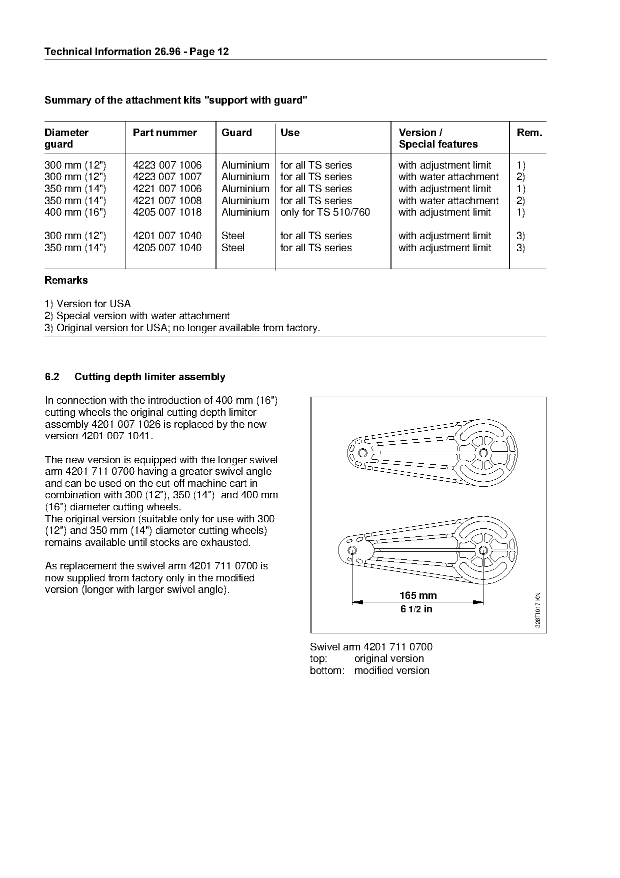
6.2===Cutting depth limiter assembly
In connection with the introduction of 400 mm (16")
cutting wheels the original cutting depth limiter
assembly 4201 007 1026 is replaced by the new

version 4201 007 1041.

The new version is equipped with the longer swivel
arm 4201 711 0700 having a greater swivel angle

and can be used on the cut-off machine cart in

combination with 300 (12"), 350 (14") and 400 mm
(16") diameter cutting wheels.
The original version (suitable only for use with 300
(12") and 350 mm (14") diameter cutting wheels)

remains available until stocks are exhausted.

As replacement the swivel arm 4201 711 0700 is

now supplied from factory only in the modified
version (longer with larger swivel angle).
                                                                                165 mm
                                                                                                             328TI017 KN

                                                                                6 1/2 in

                                                              Swivel arm 4201 711 0700
                                                              top:     original version
                                                              bottom: modified version
Page 13 of 14
Text of page 13 — search, copy, screen readers
Technical Information 26.96 - Page 13

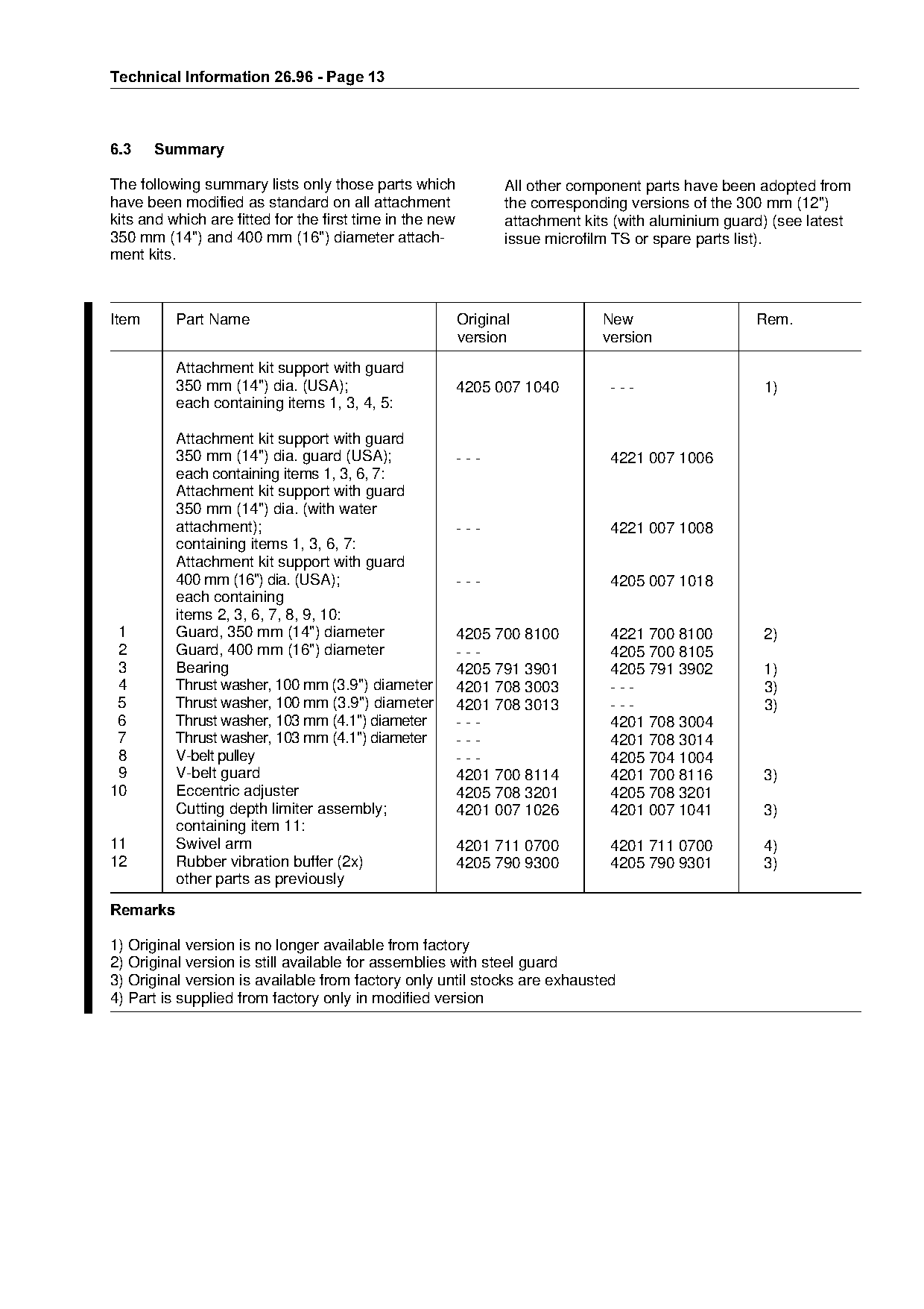
6.3====Summary

The following summary lists only those parts which               All other component parts have been adopted from
have been modified as standard on all attachment                 the corresponding versions of the 300 mm (12")
kits and which are fitted for the first time in the new          attachment kits (with aluminium guard) (see latest
350 mm (14") and 400 mm (16") diameter attach-                   issue microfilm TS or spare parts list).
ment kits.

Item      Part Name                                       Original             New                   Rem.
                                                          version              version

          Attachment kit support with guard

          350 mm (14") dia. (USA);                        4205 007 1040         ---                   1)
          each containing items 1, 3, 4, 5:

          Attachment kit support with guard

          350 mm (14") dia. guard (USA);                  ---                   4221 007 1006
          each containing items 1, 3, 6, 7:
          Attachment kit support with guard

          350 mm (14") dia. (with water
          attachment);                                    ---                   4221 007 1008
          containing items 1, 3, 6, 7:
          Attachment kit support with guard
          400 mm (16") dia. (USA);                        ---                   4205 007 1018
          each containing
          items 2, 3, 6, 7, 8, 9, 10:
 1        Guard, 350 mm (14") diameter                    4205 700 8100         4221 700 8100         2)

 2        Guard, 400 mm (16") diameter                    ---                   4205 700 8105
 3        Bearing                                         4205 791 3901         4205 791 3902         1)
 4        Thrust washer, 100 mm (3.9") diameter           4201 708 3003         ---                   3)
 5        Thrust washer, 100 mm (3.9") diameter           4201 708 3013         ---                   3)

 6        Thrust washer, 103 mm (4.1") diameter           ---                   4201 708 3004

 7        Thrust washer, 103 mm (4.1") diameter           ---                   4201 708 3014
 8        V-belt pulley                                   ---                   4205 704 1004
 9        V-belt guard                                    4201 700 8114         4201 700 8116         3)
10        Eccentric adjuster                              4205 708 3201         4205 708 3201

          Cutting depth limiter assembly;                 4201 007 1026         4201 007 1041         3)
          containing item 11:
11        Swivel arm

                                                          4201 711 0700         4201 711 0700         4)
12        Rubber vibration buffer (2x)                    4205 790 9300         4205 790 9301         3)
          other parts as previously

5HPDUNV

1) Original version is no longer available from factory

2) Original version is still available for assemblies with steel guard
3) Original version is available from factory only until stocks are exhausted
4) Part is supplied from factory only in modified version
Page 14 of 14
Text of page 14 — search, copy, screen readers
Technical Information 26.96 - Page 14

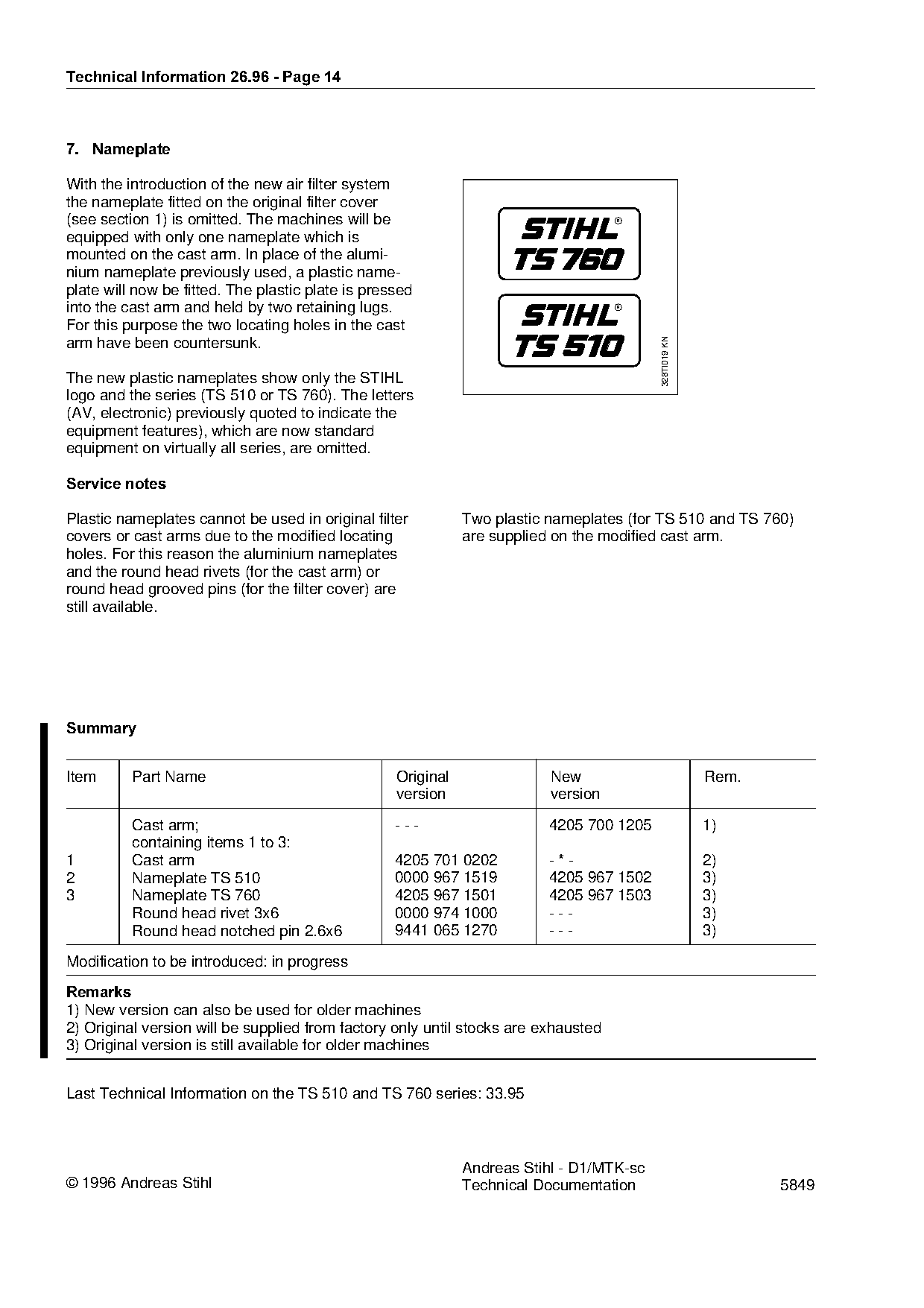
7.=Nameplate

With the introduction of the new air filter system
the nameplate fitted on the original filter cover
(see section 1) is omitted. The machines will be                                    R

equipped with only one nameplate which is
mounted on the cast arm. In place of the alumi-
nium nameplate previously used, a plastic name-
plate will now be fitted. The plastic plate is pressed
into the cast arm and held by two retaining lugs.                                   R

For this purpose the two locating holes in the cast

                                                                                          328TI019 KN
arm have been countersunk.

The new plastic nameplates show only the STIHL

logo and the series (TS 510 or TS 760). The letters
(AV, electronic) previously quoted to indicate the
equipment features), which are now standard

equipment on virtually all series, are omitted.

Service notes

Plastic nameplates cannot be used in original filter          Two plastic nameplates (for TS 510 and TS 760)
covers or cast arms due to the modified locating              are supplied on the modified cast arm.
holes. For this reason the aluminium nameplates
and the round head rivets (for the cast arm) or
round head grooved pins (for the filter cover) are
still available.

6XPPDU\

Item      Part Name                                Original               New                           Rem.
                                                   version                version

          Cast arm;                                ---                    4205 700 1205                 1)
          containing items 1 to 3:

1         Cast arm                                 4205 701 0202          -*-                           2)
2         Nameplate TS 510                         0000 967 1519          4205 967 1502                 3)
3         Nameplate TS 760                         4205 967 1501          4205 967 1503                 3)

          Round head rivet 3x6                     0000 974 1000          ---                           3)
          Round head notched pin 2.6x6             9441 065 1270          ---                           3)

Modification to be introduced: in progress

5HPDUNV
1) New version can also be used for older machines
2) Original version will be supplied from factory only until stocks are exhausted
3) Original version is still available for older machines

Last Technical Information on the TS 510 and TS 760 series: 33.95

                                                              Andreas Stihl - D1/MTK-sc
© 1996 Andreas Stihl                                          Technical Documentation                          5849
Most of these PDFs embed fonts with a shifted character map, so the text above was recovered rather than copied — read it as a faithful but imperfect transcription, and treat the page image above each block as the authority where the two disagree — the figures exist only there, because they are vector drawings that text extraction cannot keep.