Technical Information · issue 35 of 1996
New chainsaw
IssueTI 35/1996
Engine family 1124
Full text
Page 1 of 8
Text of page 1 — search, copy, screen readers
Technical Information

                                                                                                 35.96

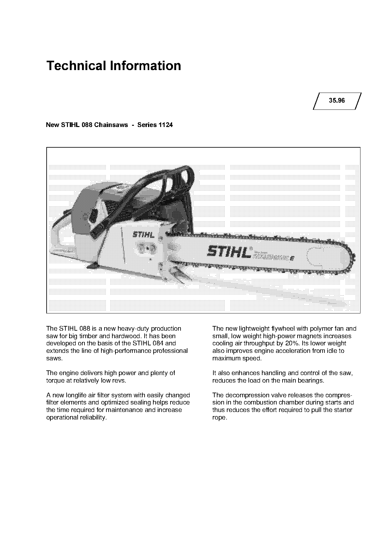
New STIHL 088 Chainsaws  -  Series 1124

The STIHL 088 is a new heavy-duty production           The new lightweight flywheel with polymer fan and
saw for big timber and hardwood. It has been           small, low weight high-power magnets increases

developed on the basis of the STIHL 084 and            cooling air throughput by 20%. Its lower weight
extends the line of high-performance professional      also improves engine acceleration from idle to

saws.                                                  maximum speed.

The engine delivers high power and plenty of           It also enhances handling and control of the saw,
torque at relatively low revs.                         reduces the load on the main bearings.

A new longlife air filter system with easily changed   The decompression valve releases the compres-
filter elements and optimized sealing helps reduce     sion in the combustion chamber during starts and

the time required for maintenance and increase         thus reduces the effort required to pull the starter
operational reliability.                               rope.
Page 2 of 8
Text of page 2 — search, copy, screen readers
Technical Information 35.96  -  Page 2

&RQWHQWV

1.    Technical Description
2.    Specifications
3.    Special Accessories for User
4.    Service Accessories
5.    Repairs
6.    Spare Parts

1.======Technical Description

Comparisons made in this chapter describe the
differences between the STIHL 088 and STIHL

084.

1.1=====Air Filter System

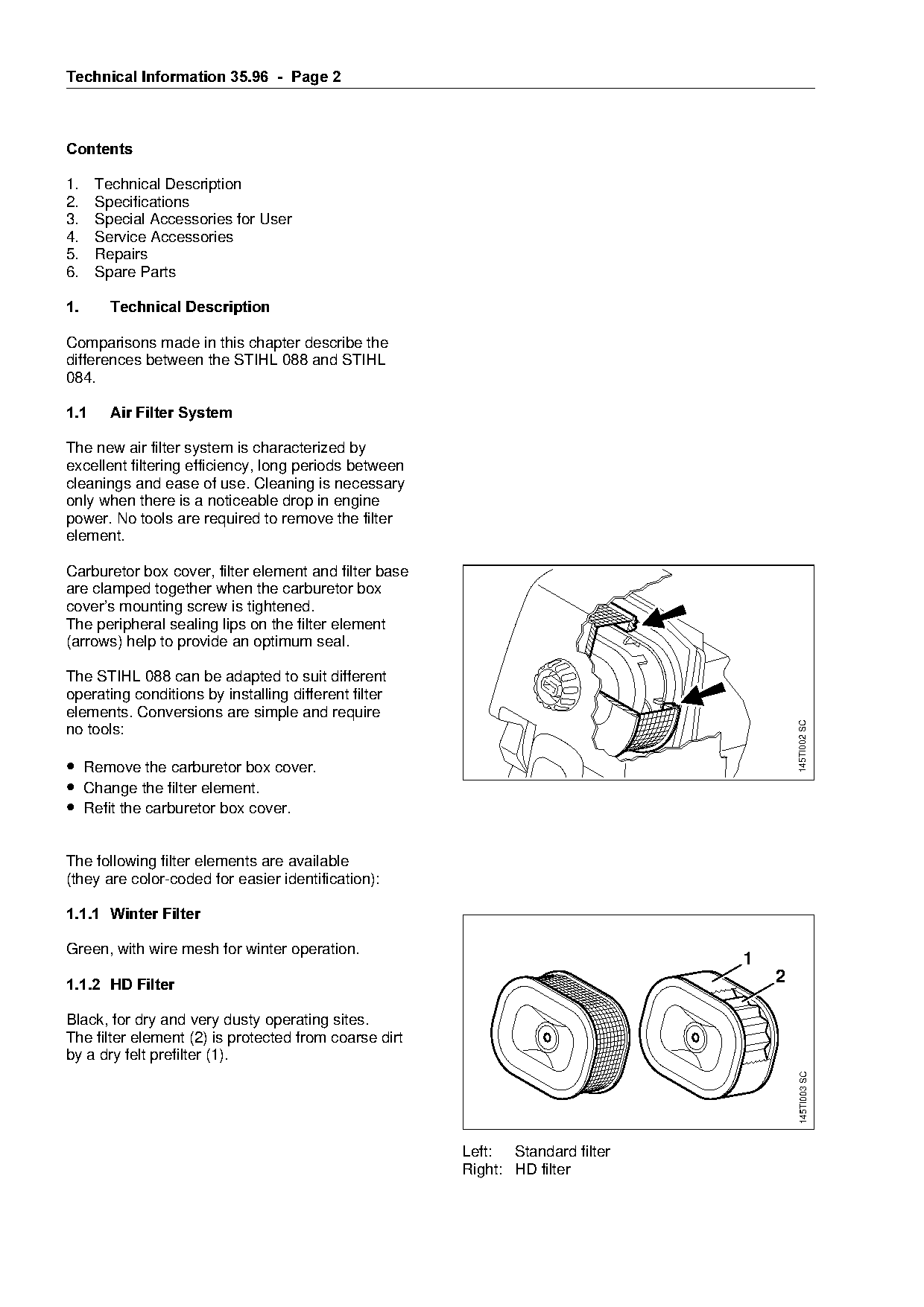
The new air filter system is characterized by
excellent filtering efficiency, long periods between
cleanings and ease of use. Cleaning is necessary

only when there is a noticeable drop in engine
power. No tools are required to remove the filter
element.

Carburetor box cover, filter element and filter base
are clamped together when the carburetor box
cover’s mounting screw is tightened.
The peripheral sealing lips on the filter element

(arrows) help to provide an optimum seal.

The STIHL 088 can be adapted to suit different
operating conditions by installing different filter

elements. Conversions are simple and require

                                                                                                  145TI002 SC
no tools:

• Remove the carburetor box cover.
• Change the filter element.
• Refit the carburetor box cover.

The following filter elements are available
(they are color-coded for easier identification):

1.1.1=Winter Filter

Green, with wire mesh for winter operation.
                                                                                          1

1.1.2=HD Filter===============================================================================O

Black, for dry and very dusty operating sites.
The filter element (2) is protected from coarse dirt
by a dry felt prefilter (1).
                                                                                                  145TI003 SC

                                                           Left: Standard filter
                                                           Right: HD filter
Page 3 of 8
Text of page 3 — search, copy, screen readers
Technical Information 35.96  -  Page 3

STIHL filters (Winter and HD) should be used in a
dry condition.
Do not impregnate with oil!

To reduce the risk of icing up, the HD filter should
be replaced by a winter filter in snow operating
conditions.

1.2===Compensator

The compensator keeps the fuel content in the
mixture constant at all times, irrespective of how

dirty the air filter is.

The mixture cannot become over-rich and it is no
longer necessary to change the setting of the high
speed screw as contamination of the air filter

builds up.

For detailed description of compensator see

TI 07.91 (STIHL 066).

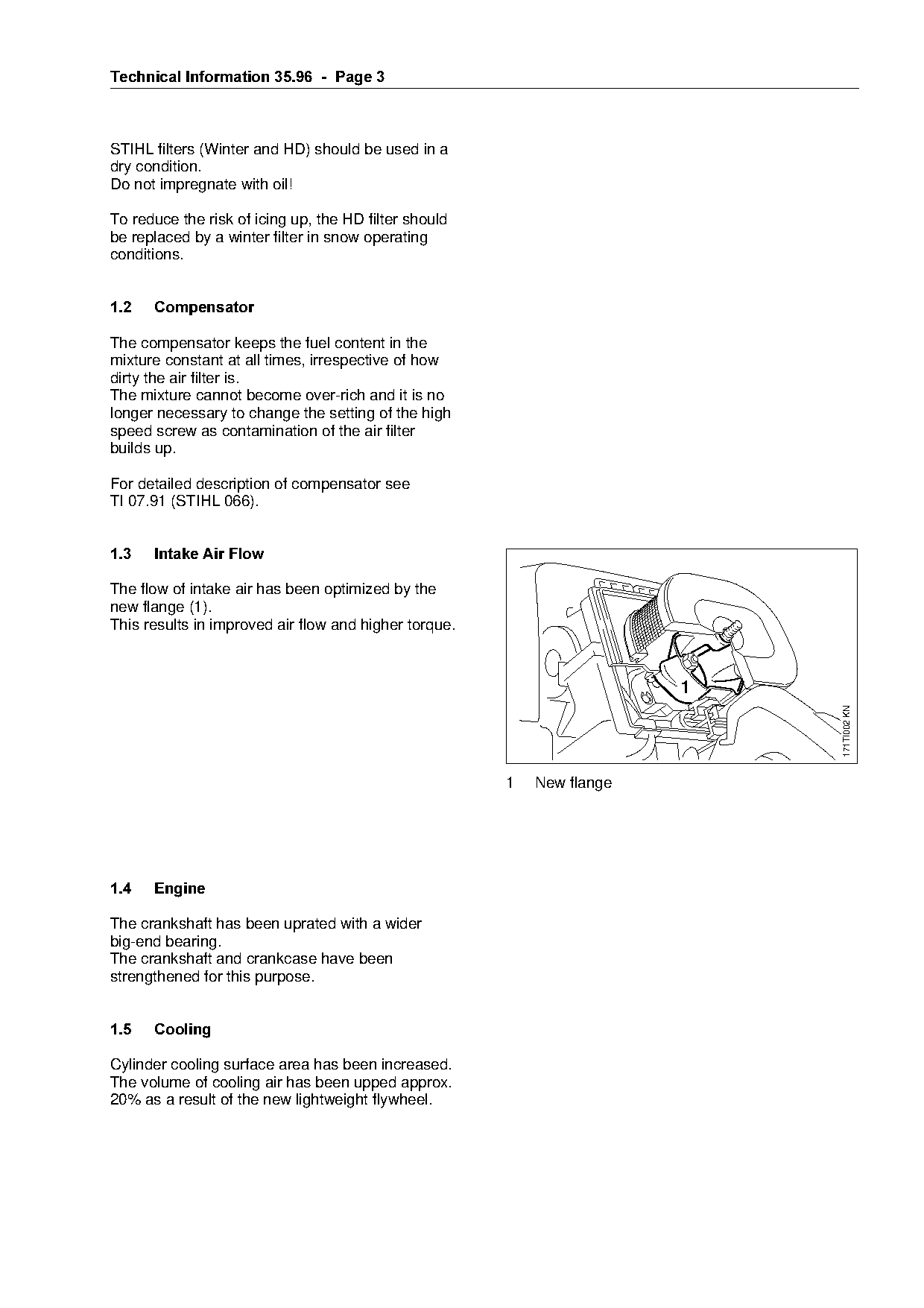
1.3===Intake Air Flow======================================fo
The flow of intake air has been optimized by the
new flange (1).
This results in improved air flow and higher torque.


                                                                               171TI002 KN

                                                       1   New flange

1.4===Engine

The crankshaft has been uprated with a wider
big-end bearing.
The crankshaft and crankcase have been

strengthened for this purpose.

1.5===Cooling

Cylinder cooling surface area has been increased.
The volume of cooling air has been upped approx.
20% as a result of the new lightweight flywheel.
Page 4 of 8
Text of page 4 — search, copy, screen readers
Technical Information 35.96  -  Page 4

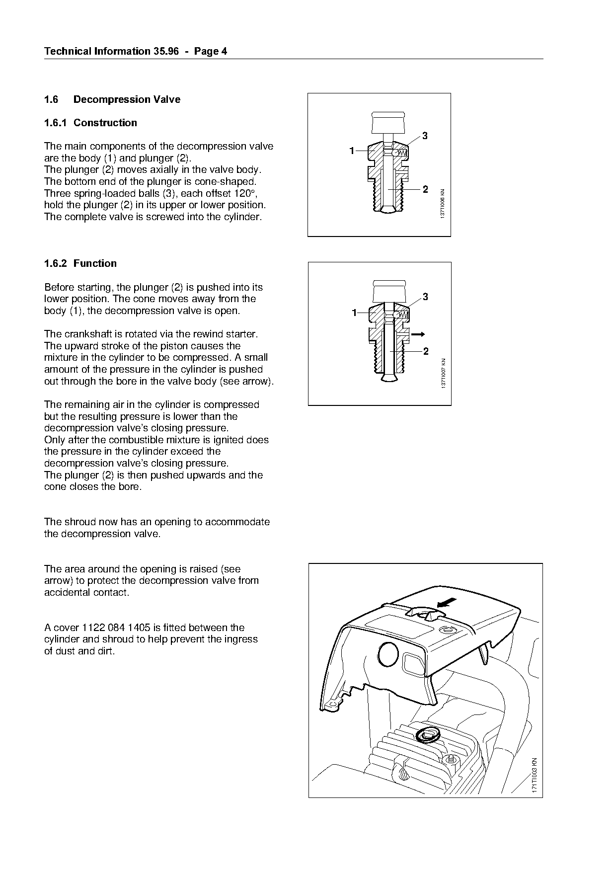
1.6===Decompression Valve

1.6.1=Construction
                                                                     3
The main components of the decompression valve              1
are the body (1) and plunger (2).
The plunger (2) moves axially in the valve body.
The bottom end of the plunger is cone-shaped.
                                                                     2

                                                                         137TI006 KN
Three spring-loaded balls (3), each offset 120°,
hold the plunger (2) in its upper or lower position.
The complete valve is screwed into the cylinder.

1.6.2=Function

Before starting, the plunger (2) is pushed into its

lower position. The cone moves away from the                         3
body (1), the decompression valve is open.                  1

The crankshaft is rotated via the rewind starter.
The upward stroke of the piston causes the
                                                                     2
mixture in the cylinder to be compressed. A small

                                                                           137TI007 KN
amount of the pressure in the cylinder is pushed
out through the bore in the valve body (see arrow).
The remaining air in the cylinder is compressed
but the resulting pressure is lower than the

decompression valve’s closing pressure.
Only after the combustible mixture is ignited does
the pressure in the cylinder exceed the
decompression valve’s closing pressure.

The plunger (2) is then pushed upwards and the
cone closes the bore.

The shroud now has an opening to accommodate
the decompression valve.

The area around the opening is raised (see
arrow) to protect the decompression valve from
accidental contact.

A cover 1122 084 1405 is fitted between the
cylinder and shroud to help prevent the ingress

of dust and dirt.
                                                                                         171TI003 KN
Page 5 of 8
Text of page 5 — search, copy, screen readers
Technical Information 35.96  -  Page 5

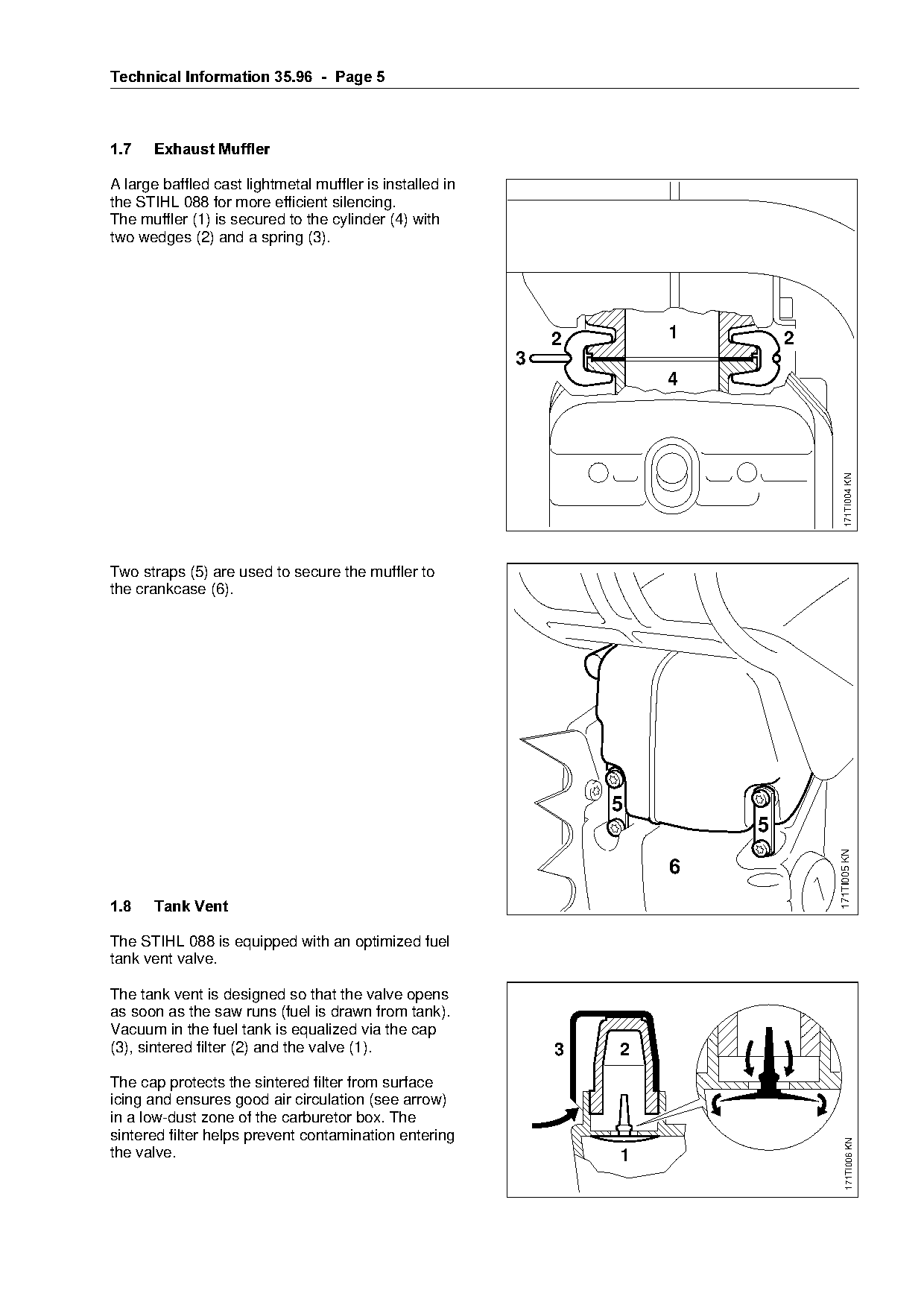
1.7====Exhaust Muffler

A large baffled cast lightmetal muffler is installed in
the STIHL 088 for more efficient silencing.
The muffler (1) is secured to the cylinder (4) with
two wedges (2) and a spring (3).

                                                               2        1       2
                                                           3


                                                                                       171TI004 KN
Two straps (5) are used to secure the muffler to
the crankcase (6).

                                                                   5
                                                                            5

                                                                                    171TI005 KN

                                                                        6
1.8====Tank Vent

The STIHL 088 is equipped with an optimized fuel
tank vent valve.

The tank vent is designed so that the valve opens
as soon as the saw runs (fuel is drawn from tank).
Vacuum in the fuel tank is equalized via the cap
(3), sintered filter (2) and the valve (1).                    3    2
The cap protects the sintered filter from surface
icing and ensures good air circulation (see arrow)
in a low-dust zone of the carburetor box. The
sintered filter helps prevent contamination entering
                                                                                        171TI006 KN

the valve.                                                          1
Page 6 of 8
Text of page 6 — search, copy, screen readers
Technical Information 35.96  -  Page 6

1.9=====Antivibration System

The rubber buffers of the STIHL 046 have been tu-
ned to reduce vibrations.

1.10=Cutting Attachments

The STIHL 088 can be equipped with the same
cutting attachments as the STIHL 084.

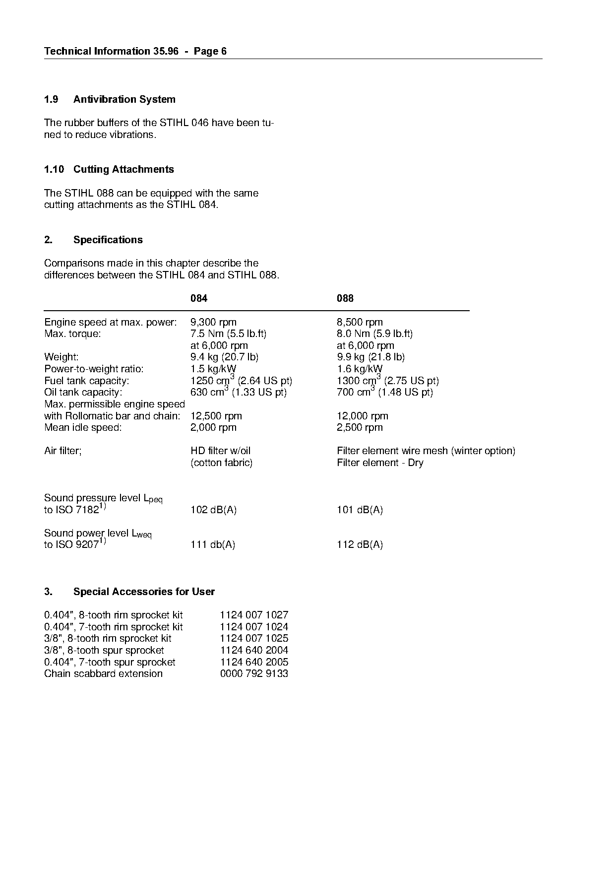
2.======Specifications

Comparisons made in this chapter describe the
differences between the STIHL 084 and STIHL 088.

                                   084=====================088

Engine speed at max. power:        9,300 rpm               8,500 rpm

Max. torque:                       7.5 Nm (5.5 lb.ft)      8.0 Nm (5.9 lb.ft)
                                   at 6,000 rpm            at 6,000 rpm
Weight:                            9.4 kg (20.7 lb)        9.9 kg (21.8 lb)
Power-to-weight ratio:
Fuel tank capacity:
                                   1.5 kg/kW
                                   1250 cm3 (2.64 US pt)
                                                           1.6 kg/kW
                                                           1300 cm3 (2.75 US pt)
Oil tank capacity:                 630 cm3 (1.33 US pt)    700 cm3 (1.48 US pt)
Max. permissible engine speed
with Rollomatic bar and chain: 12,500 rpm                  12,000 rpm

Mean idle speed:               2,000 rpm                   2,500 rpm

Air filter;                        HD filter w/oil         Filter element wire mesh (winter option)
                                   (cotton fabric)         Filter element - Dry

Sound pressure levelLpeq
to ISO 71821)                      102 dB(A)               101 dB(A)

Sound power level Lweq

to ISO 92071)                      111 db(A)               112 dB(A)

3.======Special Accessories for User

0.404", 8-tooth rim sprocket kit          1124 007 1027
0.404", 7-tooth rim sprocket kit          1124 007 1024
3/8", 8-tooth rim sprocket kit            1124 007 1025

3/8", 8-tooth spur sprocket               1124 640 2004
0.404", 7-tooth spur sprocket             1124 640 2005
Chain scabbard extension                  0000 792 9133
Page 7 of 8
Text of page 7 — search, copy, screen readers
Technical Information 35.96  -  Page 7

4.====Service Accessories

4.1===Special Servicing Tools

New part required for model 088

Part Name=========================Part No.================Application

Flange                            1124 850 4205           Sealing muffler opening for
                                                          leakage test

Other special servicing tools required are listed in the STIHL 088 service manual.

4.2===Servicing Aids

New servicing aids

Part Name=========================Part No.

Gasket set 088                    1124 007 1051
Carburetor parts kit              1124 007 1060
Gasket panel 088                  0457 281 2204             fo
Other servicing aids required are listed in the STIHL 088 service manual.

5.====Repairs

If the saw is started up in the course of repairs or
maintenance work, always observe all local

regulations and the safety precautions outlined in
the owner’s manual.

5.1===Service Notes

5.1.1=Use locking strip only when
======decompression valve is closed

Locking strip 0000 893 5903 (for blocking crank-
shaft) must not be inserted in the spark plug hole
until the decompression valve is closed. If the

decompression valve is open, it may be bent by
the force of the piston and locking strip.

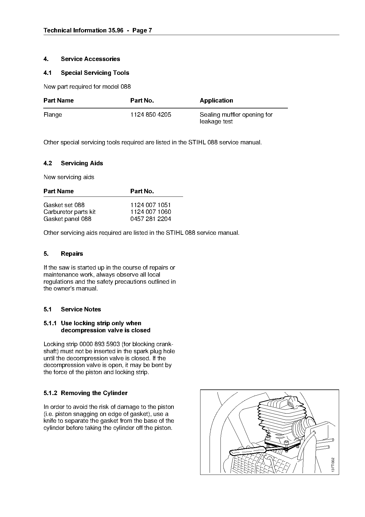
5.1.2=Removing the Cylinder

In order to avoid the risk of damage to the piston
(i.e. piston snagging on edge of gasket), use a
knife to separate the gasket from the base of the
cylinder before taking the cylinder off the piston.
                                                                                        137TI002
Page 8 of 8
Text of page 8 — search, copy, screen readers
Technical Information 35.96  -  Page 8

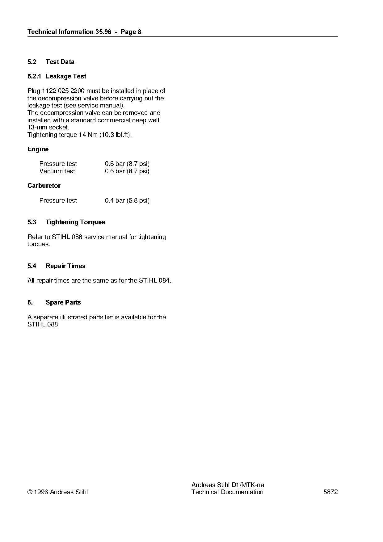
5.2=====Test Data

5.2.1=Leakage Test

Plug 1122 025 2200 must be installed in place of
the decompression valve before carrying out the
leakage test (see service manual).
The decompression valve can be removed and
installed with a standard commercial deep well
13-mm socket.
Tightening torque 14 Nm (10.3 lbf.ft).

(QJLQH

      Pressure test           0.6 bar (8.7 psi)
      Vacuum test             0.6 bar (8.7 psi)

&DUEXUHWRU

      Pressure test           0.4 bar (5.8 psi)

5.3=====Tightening Torques

Refer to STIHL 088 service manual for tightening
torques.

5.4=====Repair Times

All repair times are the same as for the STIHL 084.

6.======Spare Parts

A separate illustrated parts list is available for the
STIHL 088.

                                                             Andreas Stihl D1/MTK-na
© 1996 Andreas Stihl                                         Technical Documentation    5872
Most of these PDFs embed fonts with a shifted character map, so the text above was recovered rather than copied — read it as a faithful but imperfect transcription, and treat the page image above each block as the authority where the two disagree — the figures exist only there, because they are vector drawings that text extraction cannot keep.