Technical Information · issue 36 of 1996
New brushcutters
Model Sound Sound power
IssueTI 36/1996
Full text
Page 1 of 12
Text of page 1 — search, copy, screen readers
Technical Information

                                                                                              36.96

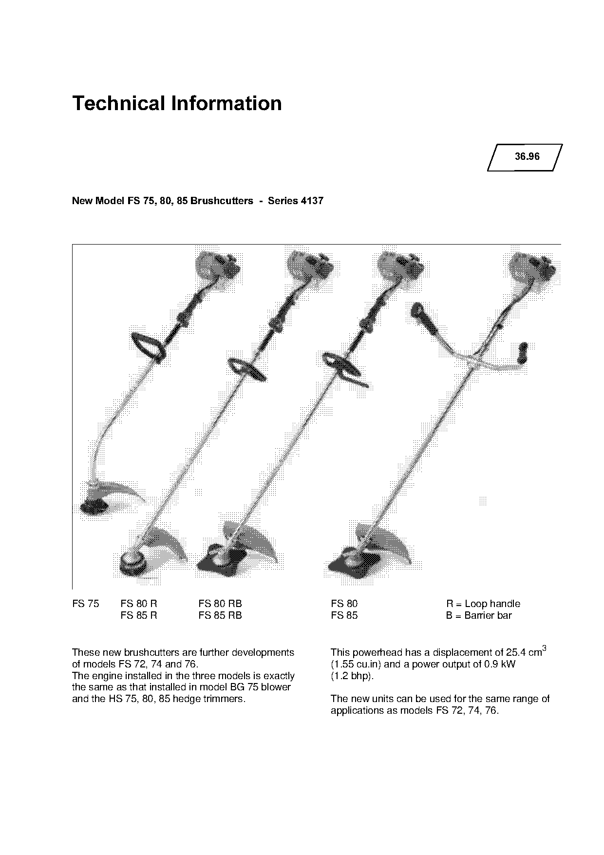
New Model FS 75, 80, 85 Brushcutters  -  Series 4137

FS 75      FS 80 R          FS 80 RB                   FS 80                   R = Loop handle
           FS 85 R          FS 85 RB                   FS 85                   B = Barrier bar

These new brushcutters are further developments        This powerhead has a displacement of 25.4 cm3
of models FS 72, 74 and 76.                            (1.55 cu.in) and a power output of 0.9 kW
The engine installed in the three models is exactly    (1.2 bhp).
the same as that installed in model BG 75 blower
and the HS 75, 80, 85 hedge trimmers.                  The new units can be used for the same range of
                                                       applications as models FS 72, 74, 76.
Page 2 of 12
Text of page 2 — search, copy, screen readers
Technical Information 36.96  -  Page 2

&RQWHQWV

1.    Technical Description
2.    Specifications
3.    Cutting Tools
4.    Special Accessories for User
5.    Service Accessories
6.    Repairs
7.    Replacement Parts

Only the differences between models FS 75, 80,
85 and models FS 72, 74, 76 are described in
the following. For further information see

TI 12.92 =models FS 72, 74 and 76=.

1.=Technical Description

&UDQNVKDIW
• Durable machined design

&\OLQGHU
• Four port technology (better mixture control,              fo
  cleaner combustion, lower emissions).
• Larger cooling area
&DUEXUHWRU
• Fixed high speed jet with one idle mixture

  adjusting screw (L; see table 2.1.2)

Air filter
• Improved filter material

• Larger effective filter surface area

Exhaust muffler
• Two-chamber muffler
• Spark arresting screen easier to remove and

     install

Rewind starter
• With ElastoStart starter grip

&RQWUROV
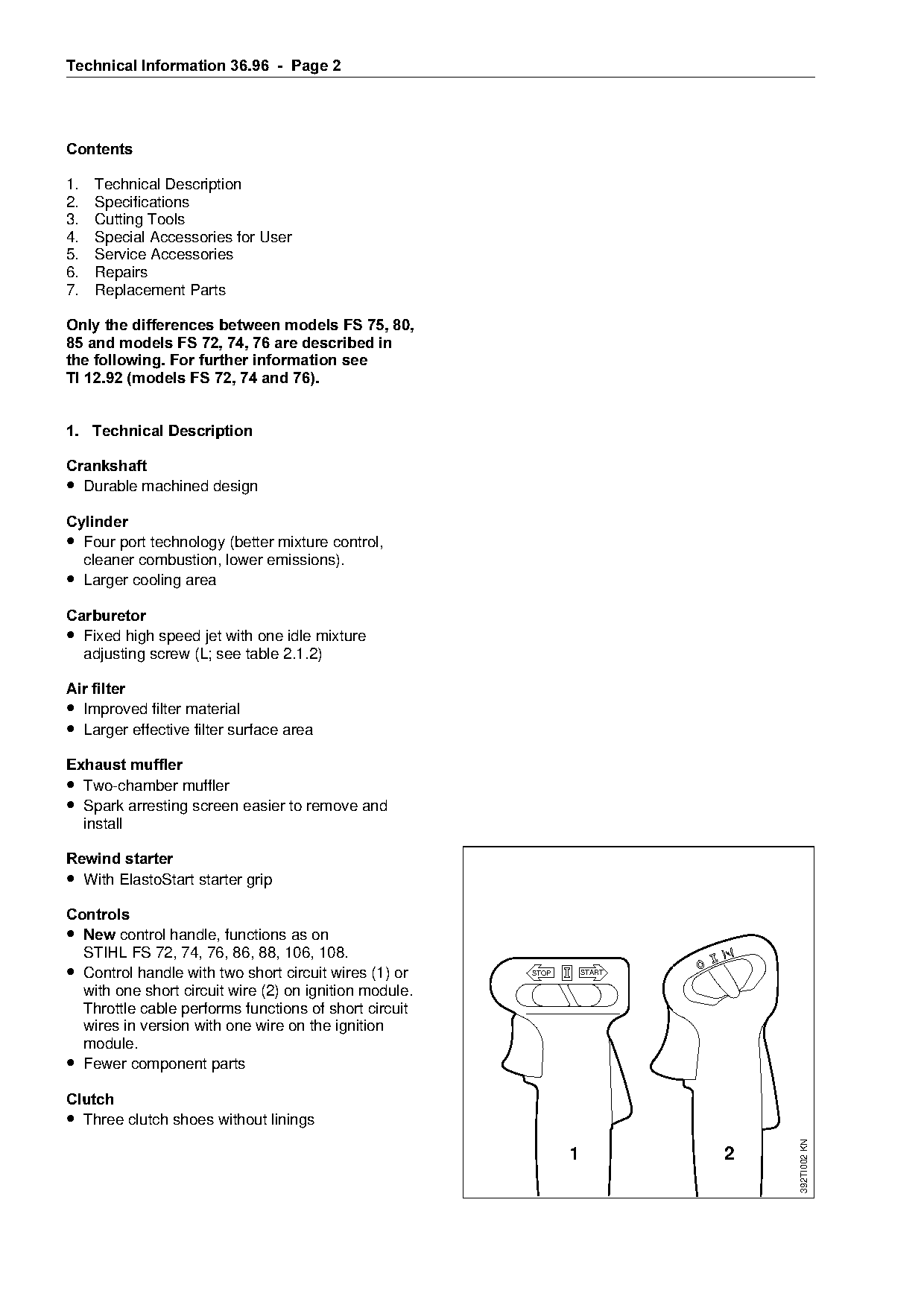
• 1HZ control handle, functions as on
     STIHL FS 72, 74, 76, 86, 88, 106, 108.

• Control handle with two short circuit wires (1) or         STOP       START

  with one short circuit wire (2) on ignition module.
  Throttle cable performs functions of short circuit
  wires in version with one wire on the ignition
  module.
• Fewer component parts
&OXWFK
• Three clutch shoes without linings
                                                                                           392TI002 KN

                                                                    1                  2
Page 3 of 12
Text of page 3 — search, copy, screen readers
Technical Information 36.96  -  Page 3

Drive shaft
• FS 75, 80=flexible shaft,
  FS 85=rigid shaft,
  supported in a protective tube on all models.
                                                                               3      4
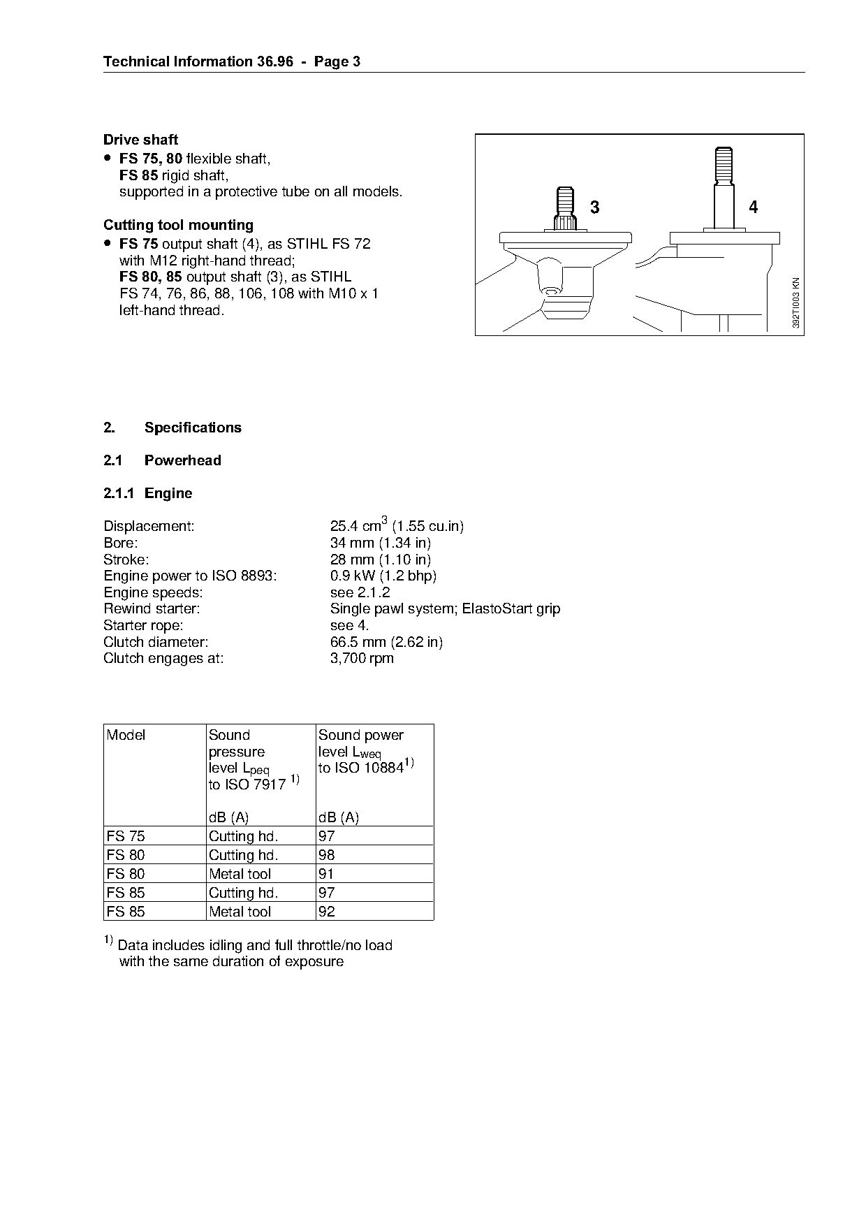
Cutting tool mounting
• FS 75=output shaft (4), as STIHL FS 72
  with M12 right-hand thread;
  FS 80, 85=output shaft (3), as STIHL

                                                                                          392TI003 KN
  FS 74, 76, 86, 88, 106, 108 with M10 x 1
  left-hand thread.

2.=======Specifications

2.1======Powerhead

2.1.1=Engine

Displacement:                           25.4 cm3 (1.55 cu.in)
Bore:                                   34 mm (1.34 in)
Stroke:                                 28 mm (1.10 in)
Engine power to ISO 8893:               0.9 kW (1.2 bhp)
Engine speeds:                          see 2.1.2

Rewind starter:                         Single pawl system; ElastoStart grip
Starter rope:                           see 4.
Clutch diameter:                        66.5 mm (2.62 in)
Clutch engages at:                      3,700 rpm

Model               Sound             Sound power
                    pressure          level Lweq

                    level Lpeq        to ISO 108841)
                    to ISO 7917 1)

                    dB (A)            dB (A)
FS 75               Cutting hd.       97

FS 80               Cutting hd.       98
FS 80               Metal tool        91
FS 85               Cutting hd.       97

FS 85               Metal tool        92
1)
     Data includes idling and full throttle/no load
     with the same duration of exposure
Page 4 of 12
Text of page 4 — search, copy, screen readers
Technical Information 36.96  -  Page 4

2.1.2=Fuel System

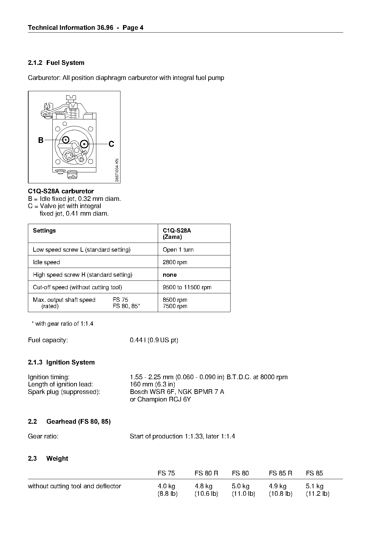
Carburetor: All position diaphragm carburetor with integral fuel pump

      B                         C

                                    366TI004 KN

C1Q-S28A carburetor
B = Idle fixed jet, 0.32 mm diam.
C = Valve jet with integral

    fixed jet, 0.41 mm diam.

 Settings=====================================================C1Q-S28A
                                                              =DPD
 Low speed screw / (standard setting)                         Open 1 turn

 Idle speed                                                   2800 rpm

 High speed screw + (standard setting)                        QRQH

 Cut-off speed (without cutting tool)                         9500 to 11500 rpm

 Max. output shaft speed         FS 75                        8500 rpm
   (rated)                       FS 80, 85*                   7500 rpm

 * with gear ratio of 1:1.4

Fuel capacity:                                    0.44 l (0.9 US pt)

2.1.3=Ignition System

Ignition timing:                                  1.55 - 2.25 mm (0.060 - 0.090 in) B.T.D.C. at 8000 rpm

Length of ignition lead:                          160 mm (6.3 in)
Spark plug (suppressed):                          Bosch WSR 6F, NGK BPMR 7 A
                                                  or Champion RCJ 6Y

2.2=======Gearhead =FS 80, 85

Gear ratio:                                       Start of production 1:1.33, later 1:1.4

2.3=======Weight

                                                            FS 75           FS 80 R     FS 80       FS 85 R     FS 85

without cutting tool and deflector                          4.0 kg          4.8 kg      5.0 kg      4.9 kg      5.1 kg
                                                            (8.8 lb)        (10.6 lb)   (11.0 lb)   (10.8 lb)   (11.2 lb)
Page 5 of 12
Text of page 5 — search, copy, screen readers
Technical Information 36.96  -  Page 5

3.=====Cutting Tools==========================================1=======================2
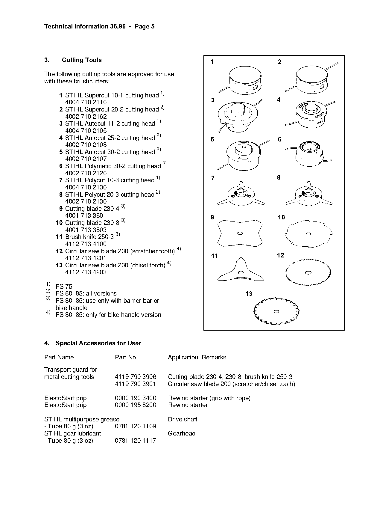
The following cutting tools are approved for use

                                                                                                681FK003
with these brushcutters:

       1=pqfei=pupercut 10-1 cutting head 1)
         QMMQ=TNM=ONNM========================================3=======================4
=====  2=pqfei=pupercut=OMJO=cutting=he~d=OF
         4002 710 2162
       3=pqfei=^utocut 11-2 cutting head 1)
         4004 710 2105
=====  4=pqfei=^utocut=ORJO=cutting=he~d=OF==================5========================6
         4002 710 2108

=====  5=pqfei=^utocut=PMJO=cutting=he~d=OF

         4002 710 2107
=====  6=pqfei=molym~tic=PMJO=cutting=he~d=OF
         4002 710 2120
                                                              7=======================8

       7=pqfei=molycut 10-3 cutting head 1)
         4004 710 2130
=====  8=pqfei=molycut=OMJP=cutting=he~d=OF

         4002 710 2130
       9=`utting blade 230-4 3)
         QMMN=TNP=PUMN=======================================9========================10
     10=`utting blade 230-8 3)
         4001 713 3803
     11=_rush knife 250-3 3)
         4112 713 4100
     12=`ircular saw blade 200 (scratcher tooth) 4)
                                                              11======================12

         4112 713 4201
     13=`ircular saw blade 200 (chisel tooth) 4)
         4112 713 4203
1)

   FS 75
2)
   FS 80, 85: all versions                                                13

3)
   FS 80, 85: use only with barrier bar or
   bike handle
4)
   FS 80, 85: only for bike handle version

4.===Special Accessories for User

Part Name                 Part No.            Application, Remarks

Transport guard for
metal cutting tools       4119 790 3906       Cutting blade 230-4, 230-8, brush knife 250-3
                          4119 790 3901       Circular saw blade 200 (scratcher/chisel tooth)

ElastoStart grip          0000 190 3400       Rewind starter (grip with rope)
ElastoStart grip          0000 195 8200       Rewind starter

STIHL multipurpose grease                     Drive shaft
- Tube 80 g (3 oz)      0781 120 1109
STIHL gear lubricant                          Gearhead
- Tube 80 g (3 oz)      0781 120 1117
Page 6 of 12
Text of page 6 — search, copy, screen readers
Technical Information 36.96  -  Page 6

4.1===Nylon Line for Cutting Heads

Line                        Application
diam. / color

.080 in/ green              Autocut 11-2
.095 in/ orange             Supercut 10-1, Supercut 20-2, Autocut 25-2, Autocut 30-2,
                            Polymatic 30-2, Polycut 10-3, Polycut 20-3
.105 in/ red                Polycut 10-3, Polycut 20-3

4.2===Sharpening Aids for Metal Cutting Tools

Part Name                   Part No.               Application
Saw set                     4020 893 5000          Circular saw blade 200 (chisel tooth)

5.====Service Accessories

5.1===Special Servicing Tools
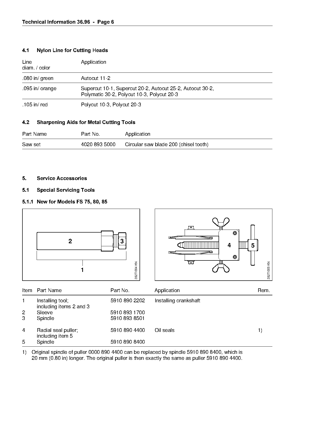
5.1.1=New for Models FS 75, 80, 85

                    2                          3
                                                                                               4    5
                                               sio     392TI004 KN

                                                                                                             392TI005 KN


Item Part Name                             Part No.                  Application                        Rem.
1     Installing tool;                     5910 890 2202             Installing crankshaft

      including items 2 and 3
2     Sleeve                               5910 893 1700
3     Spindle                              5910 893 8501

4     Radial seal puller;                  5910 890 4400             Oil seals                          1)
      including item 5
5     Spindle                              5910 890 8400
1) Original spindle of puller 0000 890 4400 can be replaced by spindle 5910 890 8400, which is
   20 mm (0.80 in) longer. The original puller is then exactly the same as puller 5910 890 4400.
Page 7 of 12
Text of page 7 — search, copy, screen readers
Technical Information 36.96  -  Page 7

5.1.2===Existing Special Servicing Tools

Use special servicing tools for FS 72, 74, 76 for all other operations not mentioned below.

Part Name                         Part No.                 Application                                   Rem.

Press sleeve                      1115 893 4600            Installing the oil seal (starter side)
Assembly sleeve                   4112 893 2400            Protecting the oil seal (starter side)
Press sleeve                      4112 893 2401            Installing the oil seal
                                                           (clutch side)
Installing tool                   4126 893 4900            Removing rubber AV element and
                                                           AV sleeve                                           1)
Installing tool                   5910 890 2208            Fitting hookless snap rings

                                                           in piston                                           2)

Service tool ZS                   5910 007 2220            Removing the crankshaft
including
- Installing tool                                          5910 890 2220

- Sleeve (1x; 30 mm)              5910 893 1701                                                                4)
- Sleeve (2x; 35 mm)              5910 893 1702                                                                4)

1)   Drive tube diameter: 25.4 mm (1")
2)   See modification 5.1.2.1
3)
4)
     See modification 5.1.2.2
     Part must be acquired for new models

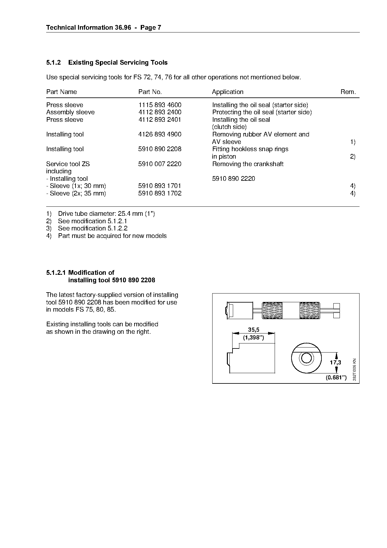
5.1.2.1=Modification of
        installing tool 5910 890 2208

The latest factory-supplied version of installing

tool 5910 890 2208 has been modified for use

in models FS 75, 80, 85.                                            6
Existing installing tools can be modified
as shown in the drawing on the right.                                     35,5

                                                                        (1,398")

                                                                                     6
                                                                                                                392TI006 KN

                                                                                                     17,3

                                                                                                    (0.681")
Page 8 of 12
Text of page 8 — search, copy, screen readers
Technical Information 36.96  -  Page 8

5.1.2.2=Modification of
         installing tool 5910 890 2220

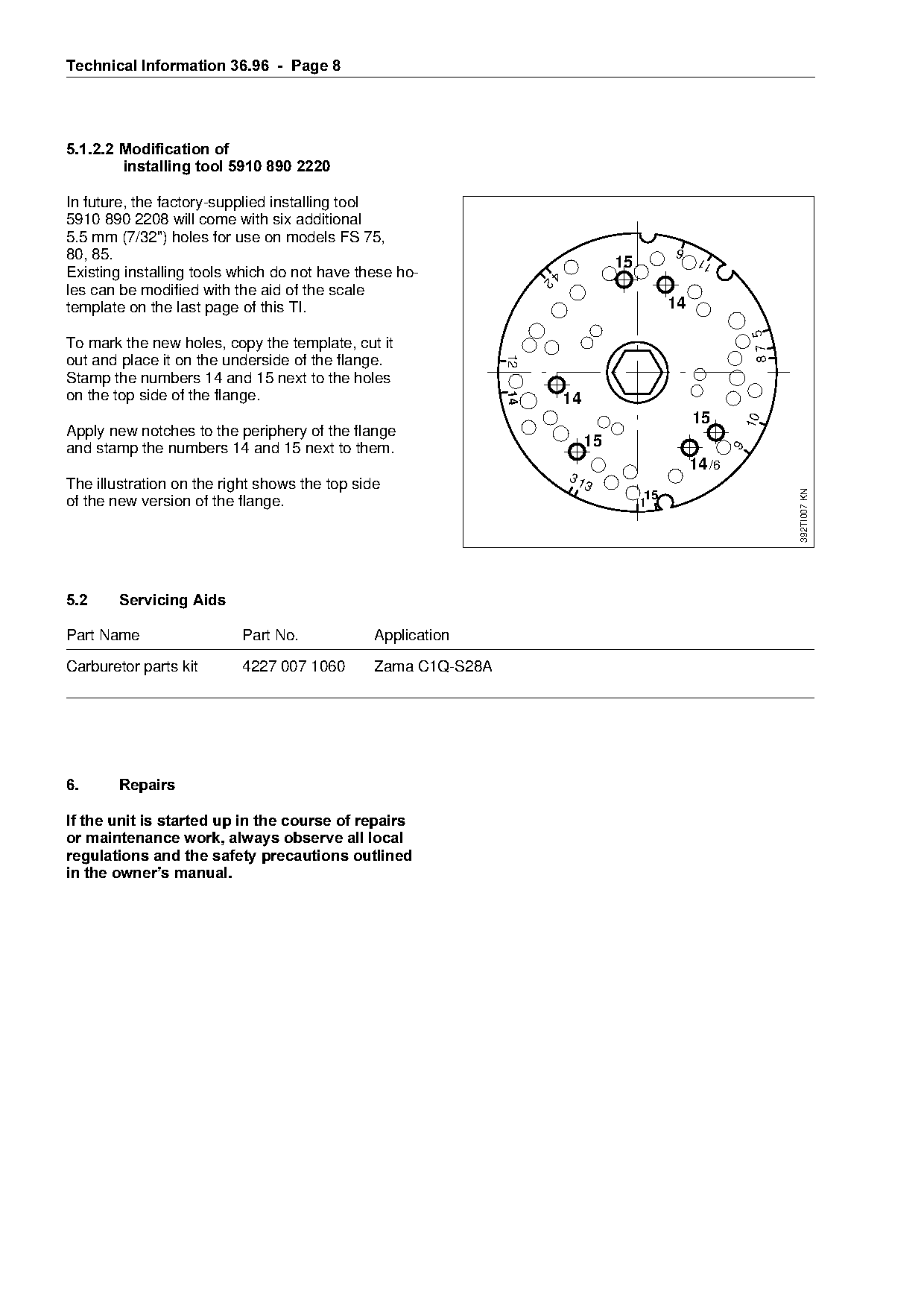
In future, the factory-supplied installing tool
5910 890 2208 will come with six additional
5.5 mm (7/32") holes for use on models FS 75,
80, 85.
                                                                                                  6
                                                                                      15               11
Existing installing tools which do not have these ho-               2
                                                                        4
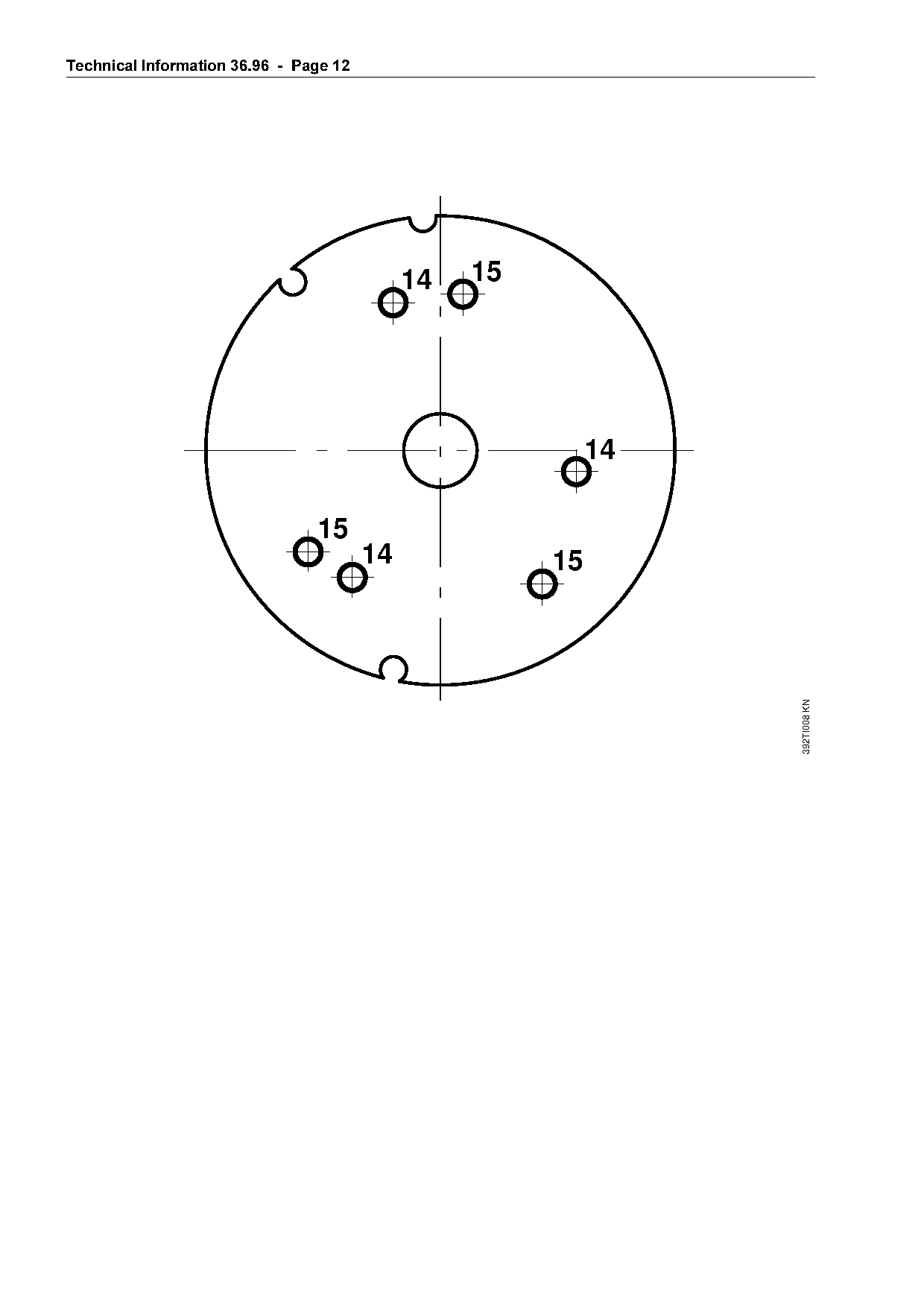
les can be modified with the aid of the scale
template on the last page of this TI.                                                            14

                                                                                                                   87 5
To mark the new holes, copy the template, cut it

                                                               12
out and place it on the underside of the flange.

Stamp the numbers 14 and 15 next to the holes

on the top side of the flange.

                                                               14
                                                                            14
                                                                                                      15

                                                                                                                  10
Apply new notches to the periphery of the flange

and stamp the numbers 14 and 15 next to them.                                    15

                                                                                                              9
                                                                                                      14 /6
                                                                            31
The illustration on the right shows the top side                                 3

                                                                                                                          392TI007 KN
                                                                                            15
of the new version of the flange.                                                          1

5.2=====Servicing Aids

Part Name                 Part No.             Application

Carburetor parts kit      4227 007 1060        Zama C1Q-S28A

6.======Repairs

If the unit is started up in the course of repairs
or maintenance work, always observe all local

regulations and the safety precautions outlined
in the owner¶s manual.
Page 9 of 12
Text of page 9 — search, copy, screen readers
Technical Information 36.96  -  Page

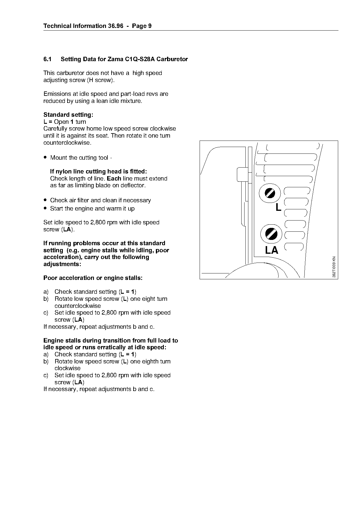
6.1===Setting Data for Zama C1Q-S28A Carburetor

This carburetor does not have a high speed
adjusting screw (H screw).

Emissions at idle speed and part-load revs are
reduced by using a lean idle mixture.

Standard setting
L = lpen 1=turn
Carefully screw home low speed screw clockwise
until it is against its seat. Then rotate it one turn
counterclockwise.

• Mount the cutting tool -
==If nylon line cutting head is fitted

  Check length of line. (DFK line must extend
  as far as limiting blade on deflector.

• Check air filter and clean if necessary
• Start the engine and warm it up                                   L
Set idle speed to 2,800 rpm with idle speed
screw (/$).
If running problems occur at this standard
setting  =e.g. engine stalls while idling, poor====================i^

acceleration=, carry out the following

                                                                        392TI009 KN
DGMXVWPHQWV

Poor acceleration or engine stalls

a) Check standard setting EL = 1F
b) Rotate low speed screw (/) one eight turn
     counterclockwise
c) Set idle speed to 2,800 rpm with idle speed

     screw (/$)
If necessary, repeat adjustments b and c.

Engine stalls during transition from full load to
idle speed or runs erratically at idle speed
a) Check standard setting EL = 1F

b) Rotate low speed screw (/) one eighth turn
     clockwise
c) Set idle speed to 2,800 rpm with idle speed

     screw (/$)
If necessary, repeat adjustments b and c.
Page 10 of 12
Text of page 10 — search, copy, screen readers
Technical Information 36.96  -  Page 10

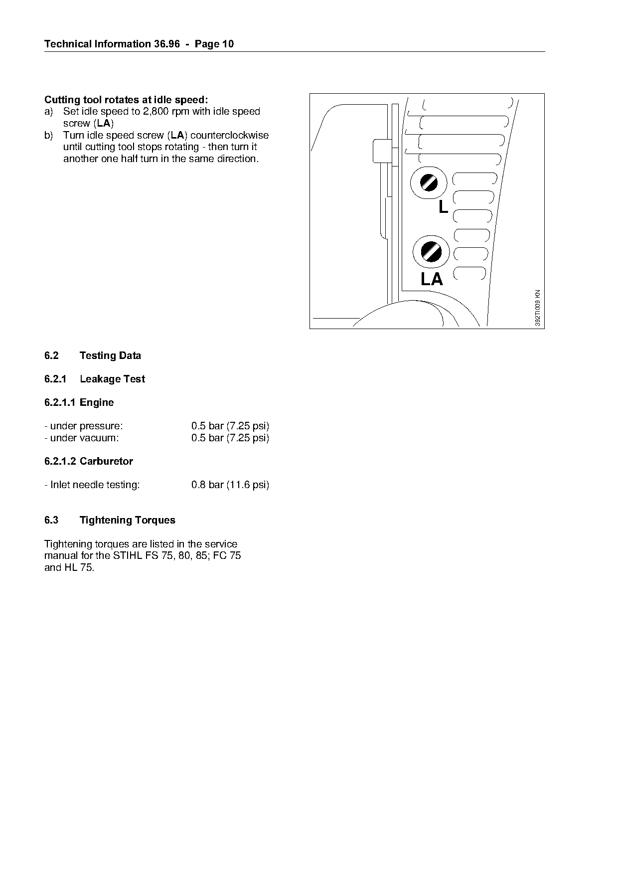
Cutting tool rotates at idle speed
a) Set idle speed to 2,800 rpm with idle speed
    screw (/$)
b) Turn idle speed screw (/$) counterclockwise
    until cutting tool stops rotating - then turn it
    another one half turn in the same direction.


                                                                          392TI009 KN
6.2=====Testing Data

6.2.1===Leakage Test
6.2.1.1=Engine

- under pressure:                 0.5 bar (7.25 psi)

- under vacuum:                   0.5 bar (7.25 psi)

6.2.1.2=Carburetor

- Inlet needle testing:           0.8 bar (11.6 psi)

6.3=====Tightening Torques

Tightening torques are listed in the service
manual for the STIHL FS 75, 80, 85; FC 75

and HL 75.
Page 11 of 12
Text of page 11 — search, copy, screen readers
Technical Information 36.96  -  Page 11

6.4===Service Note
=============================================Code===Type of Repair========================HL 75
A service manual is available for the
STIHL FS 75, 80, 85.
This service manual contains no
chapters on "Servicing the Carburetor",         1   Crankcase, Short Block                2.1
"Troubleshooting" or standard repairs.
These procedures are described in               2   Crankcase and/or Bearings             2.2
separate manuals.                               3   Crankcase Gasket, Sealing             2.0

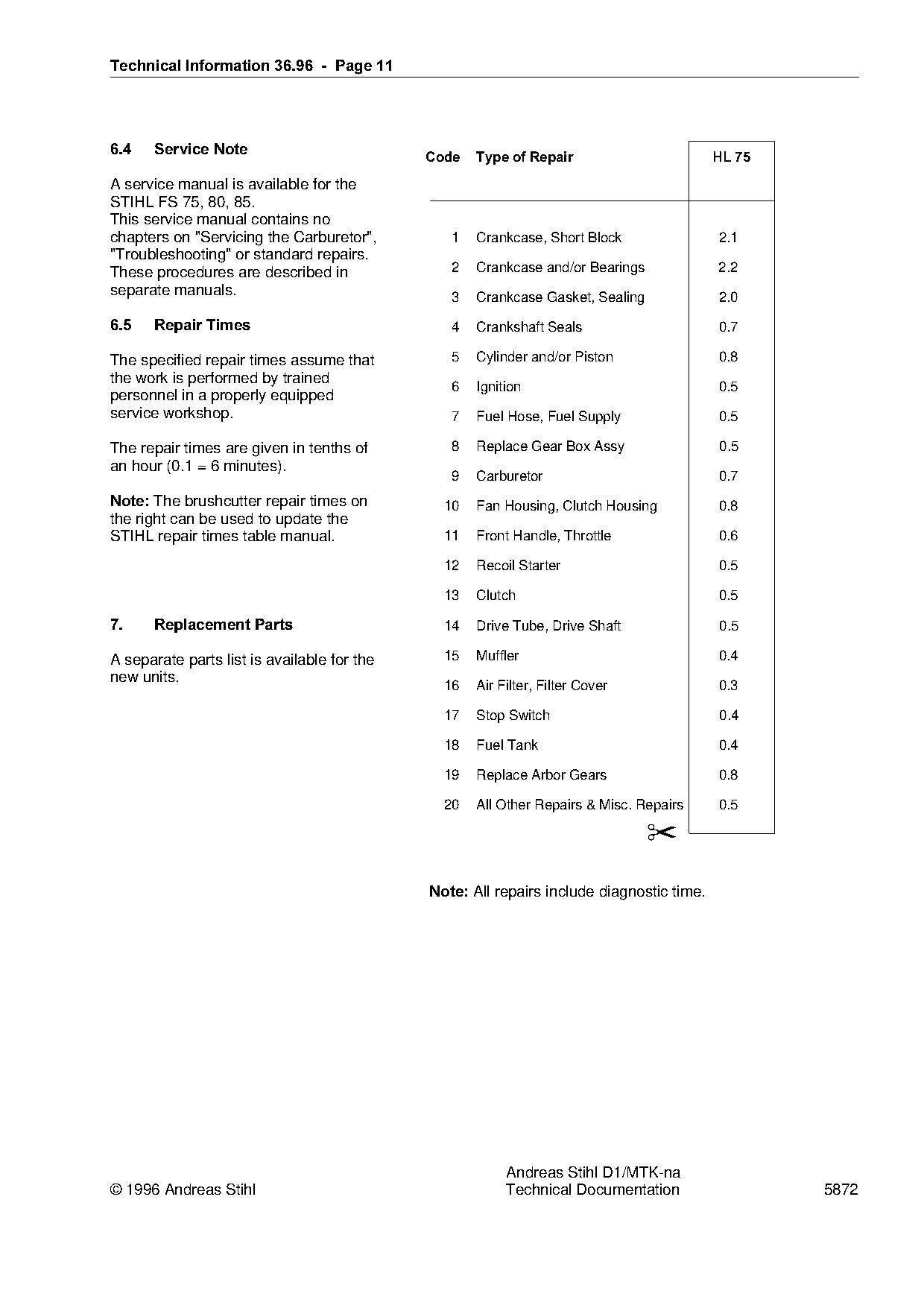
6.5===Repair Times==============================Q===`rankshaft Seals                      0.7

The specified repair times assume that          5   Cylinder and/or Piston                0.8

the work is performed by trained

                                                6   Ignition                              0.5
personnel in a properly equipped
service workshop.                               7   Fuel Hose, Fuel Supply                0.5

The repair times are given in tenths of         8   Replace Gear Box Assy                 0.5
an hour (0.1 = 6 minutes).
                                                9   Carburetor                            0.7

Note:=qhe brushcutter repair times on          10   Fan Housing, Clutch Housing           0.8
the right can be used to update the
STIHL repair times table manual.               11   Front Handle, Throttle                0.6

                                               12
                                                    Recoil Starter                        0.5

                                               13   Clutch                                0.5

7.====Replacement Parts========================NQ===arive Tube, Drive Shaft               0.5

A separate parts list is available for the     15   Muffler                               0.4
new units.                                     16   Air Filter, Filter Cover              0.3

                                               17   Stop Switch                           0.4

                                               18   Fuel Tank                             0.4

                                               19   Replace Arbor Gears                   0.8

                                               20   All Other Repairs & Misc. Repairs     0.5

                                                                                ✂

                                             Note:=^ll repairs include diagnostic time.

                                                         Andreas Stihl D1/MTK-na
© 1996 Andreas Stihl                                     Technical Documentation                  5872
Page 12 of 12
Text of page 12 — search, copy, screen readers
Technical Information 36.96  -  Page 12

                                               14   15


                                  15
                                          14             fo
                                                          15

                                                                           392TI008 KN
Most of these PDFs embed fonts with a shifted character map, so the text above was recovered rather than copied — read it as a faithful but imperfect transcription, and treat the page image above each block as the authority where the two disagree — the figures exist only there, because they are vector drawings that text extraction cannot keep.