Technical Information · issue 3 of 1997
Service notes; Service times
IssueTI 3/1997
Full text
Page 1 of 6
Text of page 1 — search, copy, screen readers
Technical Information

                                                                                                                                        03.97

Service notes, pole pruner STIHL HT 75  -  type 4138

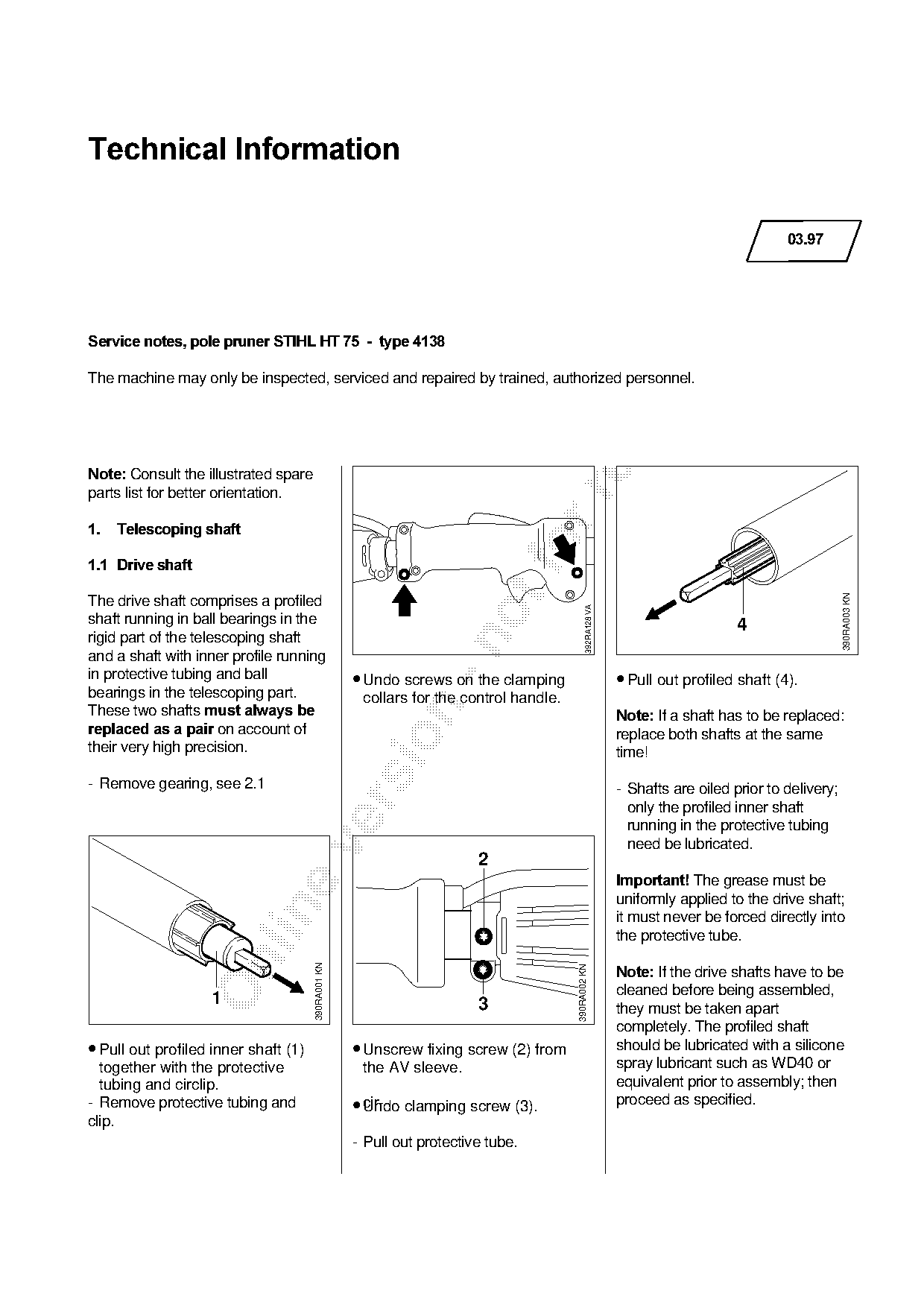
The machine may only be inspected, serviced and repaired by trained, authorized personnel.

Note:=`onsult the illustrated spare

parts list for better orientation.

1.===Telescoping shaft

1.1=Drive shaft

                                                                                                                                                    390RA003 KN
The drive shaft comprises a profiled
                                                                                              392RA128 VA

shaft running in ball bearings in the                                                                                           4
rigid part of the telescoping shaft

and a shaft with inner profile running
in protective tubing and ball                       • Undo screws on the clamping                           • Pull out profiled shaft (4).
bearings in the telescoping part.                    collars for the control handle.
qhese=two=sh~fts=must always be

                                                                                                            Note:=ff a shaft has to be replaced:
replaced as a pair=on=~ccount=of============================================================================repl~ce=both=sh~fts=~t=the=s~me

their very high precision.                                                                                  time!

- Remove gearing, see 2.1                                                                                   - Shafts are oiled prior to delivery;

                                                                                                              only the profiled inner shaft
                                                                                                              running in the protective tubing
                                                                                                              need be lubricated.

                                                                        2
                                                                                                            Important!=qhe grease must be
                                                                                                            uniformly applied to the drive shaft;

                                                                                                            it must never be forced directly into
                                                                                                            the protective tube.

                                                                                                            Note:=ff the drive shafts have to be
                                      390RA001 KN

                                                                                       390RA002 KN

                                                                                                            cleaned before being assembled,
                   1                                                    3                                   they must be taken apart
                                                                                                            completely. The profiled shaft
• Pull out profiled inner shaft (1)                 • Unscrew fixing screw (2) from                         should be lubricated with a silicone
  together with the protective                       the AV sleeve.                                         spray lubricant such as WD40 or
  tubing and circlip.                                                                                       equivalent prior to assembly; then
- Remove protective tubing and                      • cir-
                                                      Undo clamping screw (3).                              proceed as specified.
clip.
                                                    - Pull out protective tube.
Page 2 of 6
Text of page 2 — search, copy, screen readers
Technical Information 03.97 - Page 2

                                      390RA004 KN
                   4

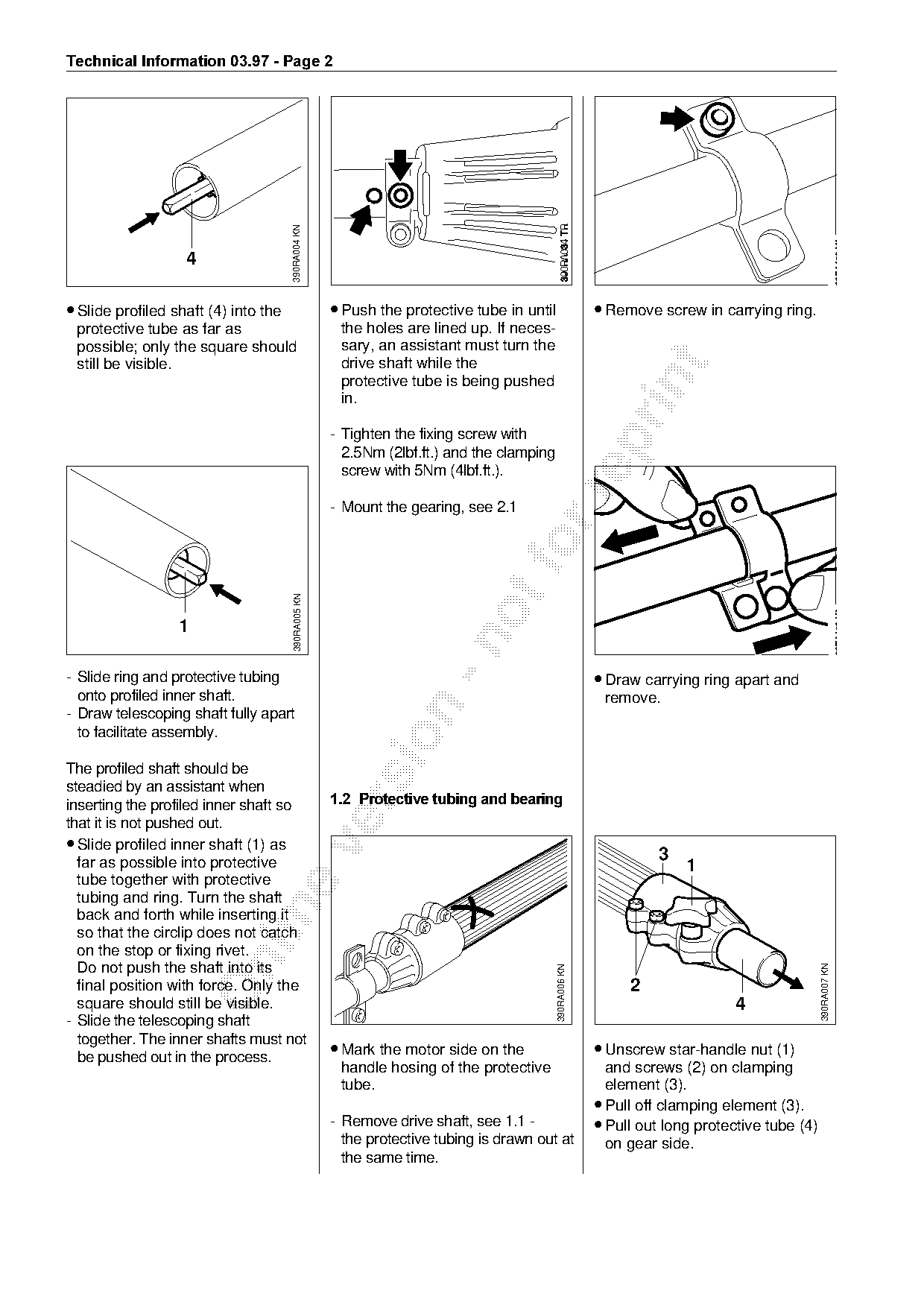
• Slide profiled shaft (4) into the                  • Push the protective tube in until                 • Remove screw in carrying ring.
 protective tube as far as                            the holes are lined up. If neces-
 possible; only the square should                     sary, an assistant must turn the
 still be visible.                                    drive shaft while the

                                                      protective tube is being pushed

                                                      in.

                                                     - Tighten the fixing screw with

                                                       2.5Nm (2lbf.ft.) and the clamping
                                                       screw with 5Nm (4lbf.ft.).

                                                     - Mount the gearing, see 2.1

                                       390RA005 KN


- Slide ring and protective tubing                                                                       • Draw carrying ring apart and
  onto profiled inner shaft.                                                                              remove.

- Draw telescoping shaft fully apart
  to facilitate assembly.

The profiled shaft should be
steadied by an assistant when
=====================================================1.2=Protective tubing and bearing

inserting the profiled inner shaft so
that it is not pushed out.
• Slide profiled inner shaft (1) as

  far as possible into protective                                                                                  3
                                                                                                                       1
  tube together with protective
  tubing and ring. Turn the shaft

  back and forth while inserting it
  so that the circlip does not catch
  on the stop or fixing rivet.

  Do not push the shaft into its
                                                                                                                                               390RA007 KN
                                                                                           390RA006 KN

  final position with force. Only the                                                                         2
  square should still be visible.                                                                                              4
- Slide the telescoping shaft
  together. The inner shafts must not
  be pushed out in the process.                      • Mark the motor side on the                        • Unscrew star-handle nut (1)
                                                      handle hosing of the protective                      and screws (2) on clamping
                                                      tube.                                                element (3).
                                                                                                         • Pull off clamping element (3).
                                                     - Remove drive shaft, see 1.1 -                     • Pull out long protective tube (4)
                                                       the protective tubing is drawn out at               on gear side.
                                                       the same time.
Page 3 of 6
Text of page 3 — search, copy, screen readers
Technical Information 03.97 - Page 3

                    5                                                   11


                                                                                                                                              390RA013 KN
                                                                                           390RA011 KN
                                       390RA008 KN
                              6                                                   12
            7

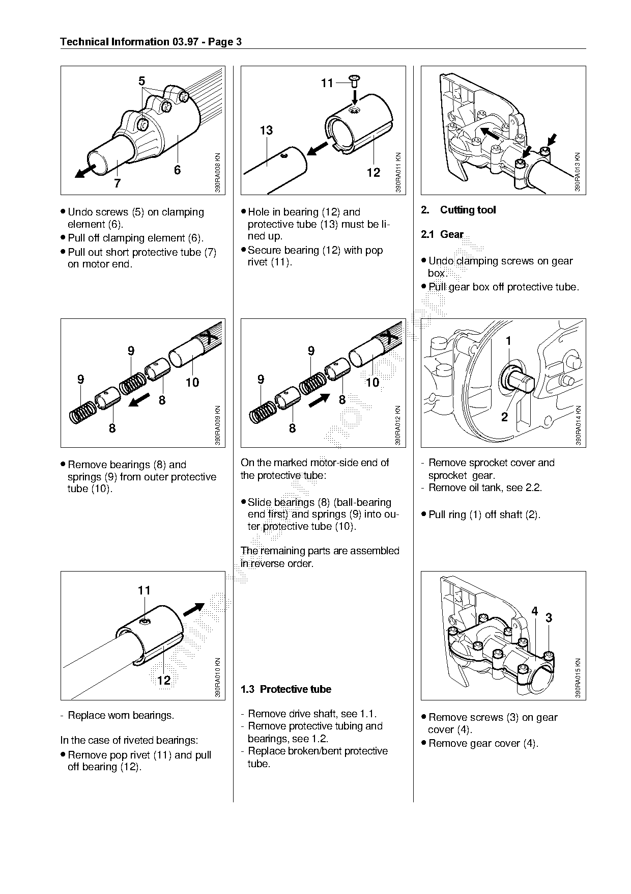
• Undo screws (5) on clamping                        • Hole in bearing (12) and                          2.===Cutting tool
  element (6).                                         protective tube (13) must be li-
• Pull off clamping element (6).                       ned upK===========================================2.1=Gear
• Pull out short protective tube (7)                 • Secure bearing (12) with pop

                                                                                                         • Undo clamping screws on gear

  on motor end.                                        rivet (11).
                                                                                                          box.
                                                                                                         • Pull gear box off protective tube.

                                                                                                                              1
                9                                                   9

   9                              10                    9                        fo
                                                                                  10
                         8                                                   8

                                                                                                                                               390RA014 KN
                                       390RA009 KN

                                                                                          390RA012 KN

                                                                                                                             2
           8                                                    8

• Remove bearings (8) and                            On the marked motor-side end of                     - Remove sprocket cover and
 springs (9) from outer protective                   the protective tube:                                  sprocket gear.

 tube (10).                                                                                              - Remove oil tank, see 2.2.
                                                     • Slide bearings (8) (ball-bearing

                                                      end first) and springs (9) into ou-                • Pull ring (1) off shaft (2).
                                                      ter protective tube (10).

                                                     The remaining parts are assembled
                                                     in reverse order.

                    11
                                                                                                                                    4
                                                                                                                                          3
                                       390RA010 KN

                                                                                                                                              390RA015 KN

                         12
                                                     1.3=Protective tube

- Replace worn bearings.                             - Remove drive shaft, see 1.1.                      • Remove screws (3) on gear
                                                     - Remove protective tubing and                        cover (4).
In the case of riveted bearings:                       bearings, see 1.2.                                • Remove gear cover (4).
• Remove pop rivet (11) and pull                     - Replace broken/bent protective
  off bearing (12).                                    tube.
Page 4 of 6
Text of page 4 — search, copy, screen readers
Technical Information 03.97 - Page 4

                                                                           11
                                                                       2                                                           9
                                 6                          10
                                                                                                                                            7

                                                                                                                                                 390RA022 KN
                                                                                           390RA019 KN
                                     390RA016 KN
              5

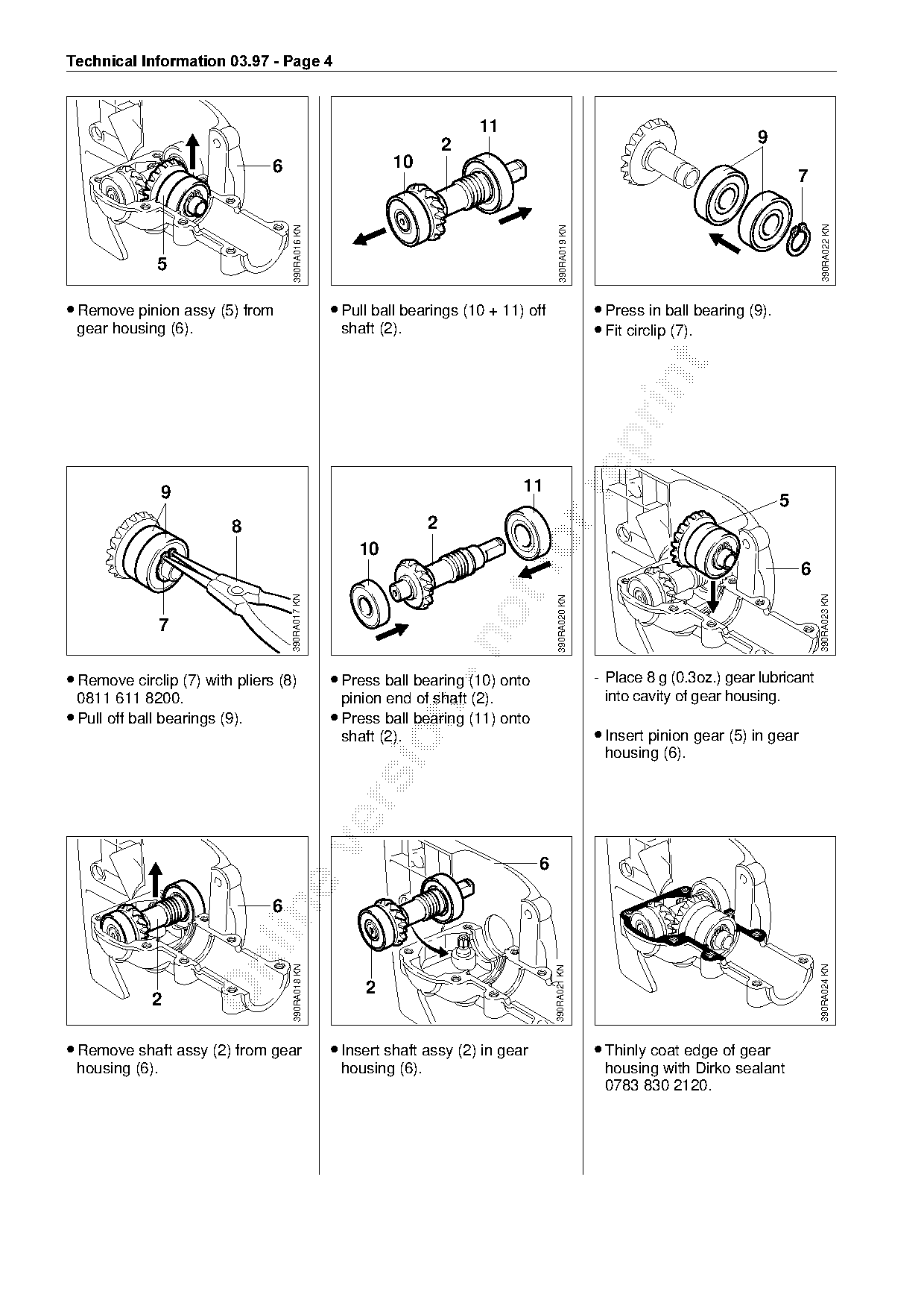
• Remove pinion assy (5) from                      • Pull ball bearings (10 + 11) off                    • Press in ball bearing (9).
 gear housing (6).                                  shaft (2).                                           • Fit circlip (7).

                9                                                                11

                                                                                                                                        5
                           8                                       2
                                                       10                       fo                                                          6
                                     390RA017 KN

                                                                                                                                                390RA023 KN
                                                                                          390RA020 KN


• Remove circlip (7) with pliers (8)               • Press ball bearing (10) onto                        - Place 8 g (0.3oz.) gear lubricant
 0811 611 8200.                                     pinion end of shaft (2).                               into cavity of gear housing.

• Pull off ball bearings (9).                      • Press ball bearing (11) onto
                                                    shaft (2).                                           • Insert pinion gear (5) in gear

                                                                                                          housing (6).


                                 6
                                     390RA018 KN

                                                                                                                                                390RA024 KN
                                                                                         390RA021 KN

                                                        2
              2

• Remove shaft assy (2) from gear                  • Insert shaft assy (2) in gear                       • Thinly coat edge of gear
 housing (6).                                       housing (6).                                          housing with Dirko sealant
                                                                                                          0783 830 2120.
Page 5 of 6
Text of page 5 — search, copy, screen readers
Technical Information 03.97 - Page 5


                                   4
                                                                                                                                        2

                                                                                       390RA027 KN
                                       390RA025 KN

                                                                                                                                             390RA030 KN
                                                                                                                                    1

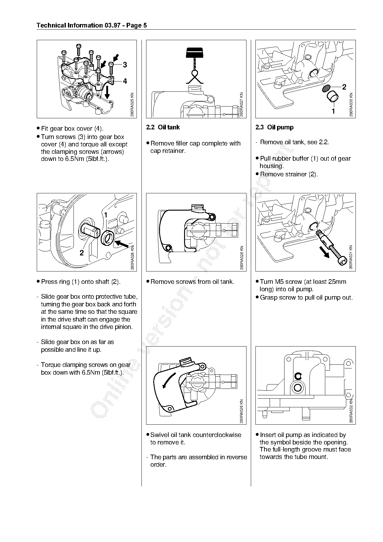
• Fit gear box cover EQFK=============================2.2=Oil tank====================================2.3=Oil pump
• Turn screws (3) into gear box
 cover (4) and torque all except                      • Remove filler cap complete with               - Remove oil tank, see 2.2.
                                                       cap retainer.

 the clamping screws (arrows)
                                                                                                      • Pull rubber buffer (1) out of gear

 down to 6.5Nm (5lbf.ft.).
                                                                                                       housing.
                                                                                                      • Remove strainer (2).


                                                                                                                                            390RA031 KN
                                                                                        390RA028 KN
                                        390RA026 KN


• Press ring (1) onto shaft (2).                      • Remove screws from oil tank.                  • Turn M5 screw (at least 25mm
                                                                                                       long) into oil pump.

- Slide gear box onto protective tube,                                                                • Grasp screw to pull oil pump out.
  turning the gear box back and forth

  at the same time so that the square
  in the drive shaft can engage the
  internal square in the drive pinion.

- Slide gear box on as far as
  possible and line it up.

- Torque clamping screws on gear
  box down with 6.5Nm (5lbf.ft.).

                                                                                                                                            390RA032 KN
                                                                                       390RA029 KN

                                                      • Swivel oil tank counterclockwise              • Insert oil pump as indicated by
                                                       to remove it.                                   the symbol beside the opening.
                                                                                                       The full-length groove must face
                                                      - The parts are assembled in reverse             towards the tube mount.
                                                        order.
Page 6 of 6
Text of page 6 — search, copy, screen readers
Technical Information 03.97 - Page 6

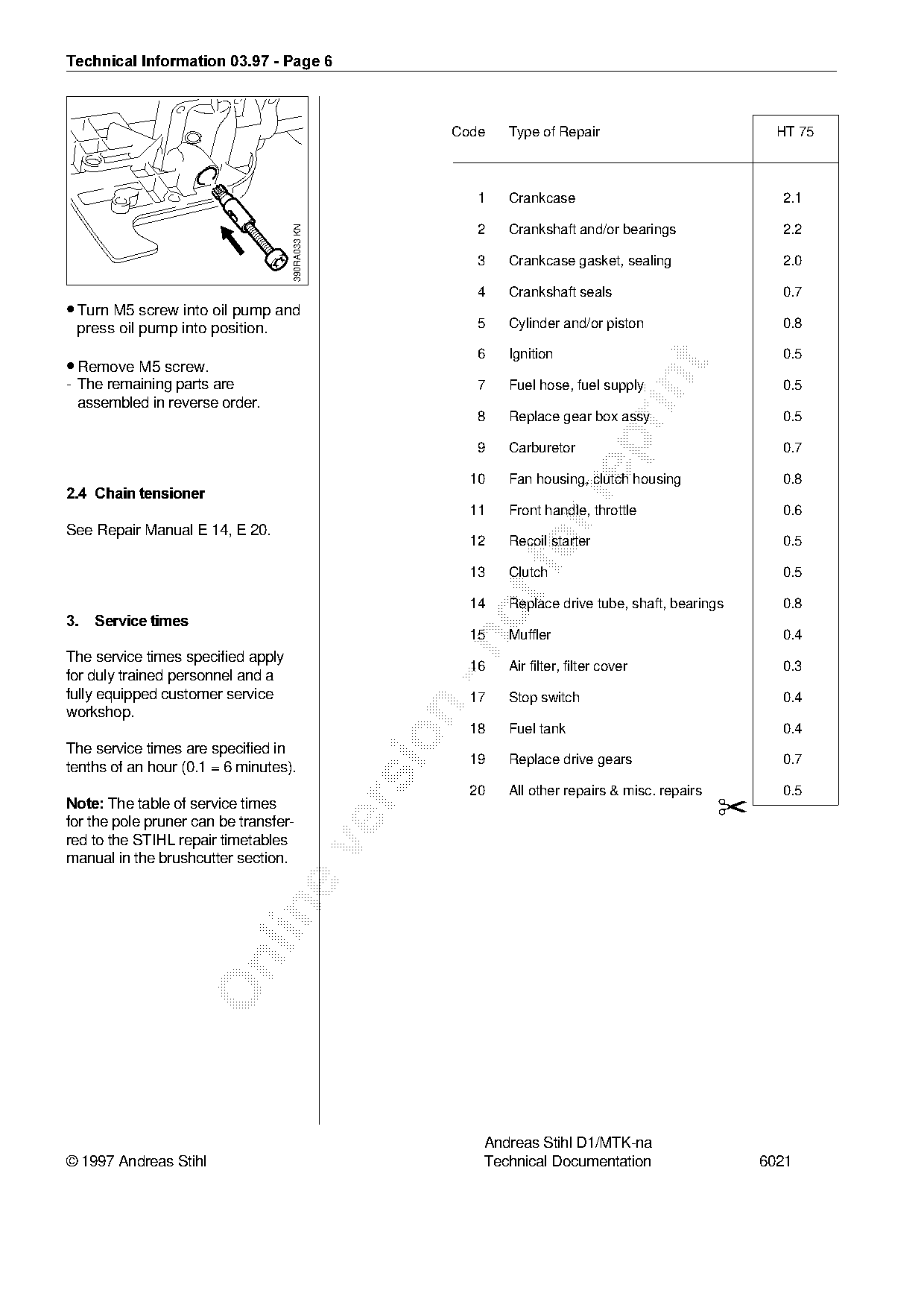
                                                        Code    Type of Repair                            HT 75

                                                            1   Crankcase                                 2.1

                                    390RA033 KN
                                                            2   Crankshaft and/or bearings                2.2

                                                            3   Crankcase gasket, sealing                 2.0

                                                            4   Crankshaft seals                          0.7
• Turn M5 screw into oil pump and
 press oil pump into position.                              5   Cylinder and/or piston                    0.8

                                                            6   Ignition                                  0.5
• Remove M5 screw.

- The remaining parts are                                   7   Fuel hose, fuel supply                    0.5
  assembled in reverse order.
                                                            8   Replace gear box assy                     0.5

                                                            9   Carburetor                                0.7

                                                           10   Fan housing, clutch housing               0.8
2.4=Chain tensioner

                                                           11   Front handle, throttle                    0.6
See Repair Manual E 14, E 20.
                                                           12

                                                           13
                                                                Recoil starter

                                                                Clutch
                                                                                                          0.5

                                                                                                          0.5
                                                           14   Replace drive tube, shaft, bearings       0.8
3.===Service times
                                                           15   Muffler                                   0.4

The service times specified apply
                                                           16   Air filter, filter cover                  0.3
for duly trained personnel and a
fully equipped customer service                            17   Stop switch                               0.4

workshop.
                                                           18   Fuel tank                                 0.4

The service times are specified in
                                                           19   Replace drive gears                       0.7
tenths of an hour (0.1 = 6 minutes).
                                                           20   All other repairs & misc. repairs         0.5
Note:=qhe table of service times
                                                                                                    ✂

for the pole pruner can be transfer-
red to the STIHL repair timetables

manual in the brushcutter section.

                                                            Andreas Stihl D1/MTK-na
© 1997 Andreas Stihl                                        Technical Documentation                     6021
Most of these PDFs embed fonts with a shifted character map, so the text above was recovered rather than copied — read it as a faithful but imperfect transcription, and treat the page image above each block as the authority where the two disagree — the figures exist only there, because they are vector drawings that text extraction cannot keep.