Technical Information · issue 11 of 1997
FS 36-44, FC 44, BR 320, 320 L, 400: Carburetor (n
Model Basic setting Basic setting
IssueTI 11/1997
Full text
Page 1 of 7
Text of page 1 — search, copy, screen readers
Technical Information

                                                                                       11.97

Model BR 320, 320 L, 400 Blowers=====================- Series 4203
Model FS 36, 40, 44 Brushcutters=====================- Series 4130
Model FC 44 Power Edger==============================- Series 4130

New CARB and EPA Regulations

1.=Carburetors

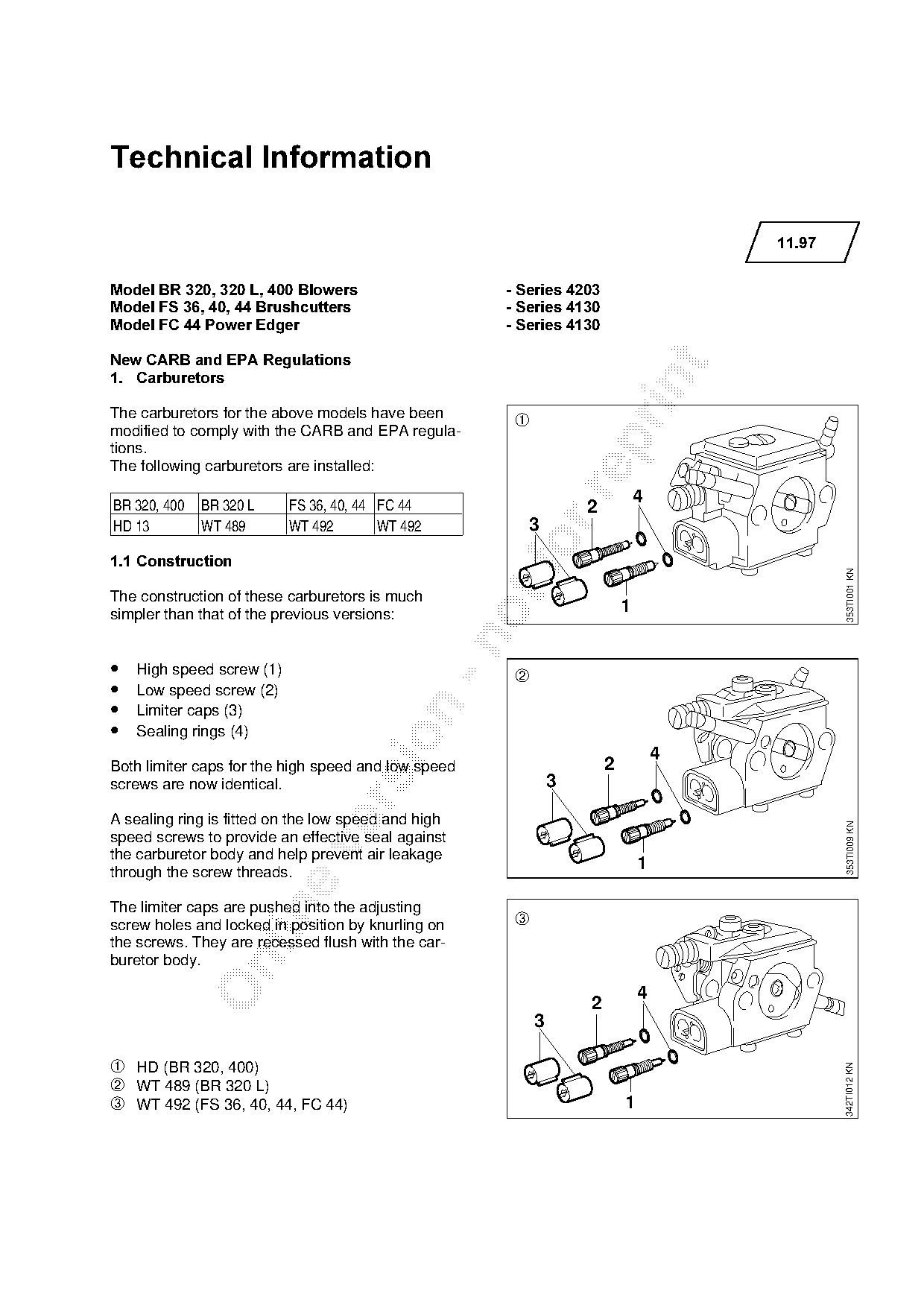
The carburetors for the above models have been
                                                       ➀
modified to comply with the CARB and EPA regula-

tions.
The following carburetors are installed:

BR 320, 400   BR 320 L     FS 36, 40, 44 FC 44
                                                                               4
                                                                   2
HD 13         WT 489       WT 492        WT 492         3
1.1=Construction

                                                                                               353TI001 KN
The construction of these carburetors is much
simpler than that of the previous versions:                                1

•   High speed screw (1)                               ➁
•   Low speed screw (2)
•

    Limiter caps (3)
•   Sealing rings (4)

                                                                                   4
Both limiter caps for the high speed and low speed                     2
screws are now identical.                                      3

A sealing ring is fitted on the low speed and high
                                                                                                353TI009 KN
speed screws to provide an effective seal against

the carburetor body and help prevent air leakage
through the screw threads.
                                                                               1

The limiter caps are pushed into the adjusting

screw holes and locked in position by knurling on      ➂
the screws. They are recessed flush with the car-
buretor body.

                                                                               4
                                                                   2
                                                           3

➀ HD (BR 320, 400)
                                                                                               342TI012 KN

➁ WT 489 (BR 320 L)
➂ WT 492 (FS 36, 40, 44, FC 44)                                            1
Page 2 of 7
Text of page 2 — search, copy, screen readers
Technical Information 11.97  -  Page 2

1.2=Function of limiter caps

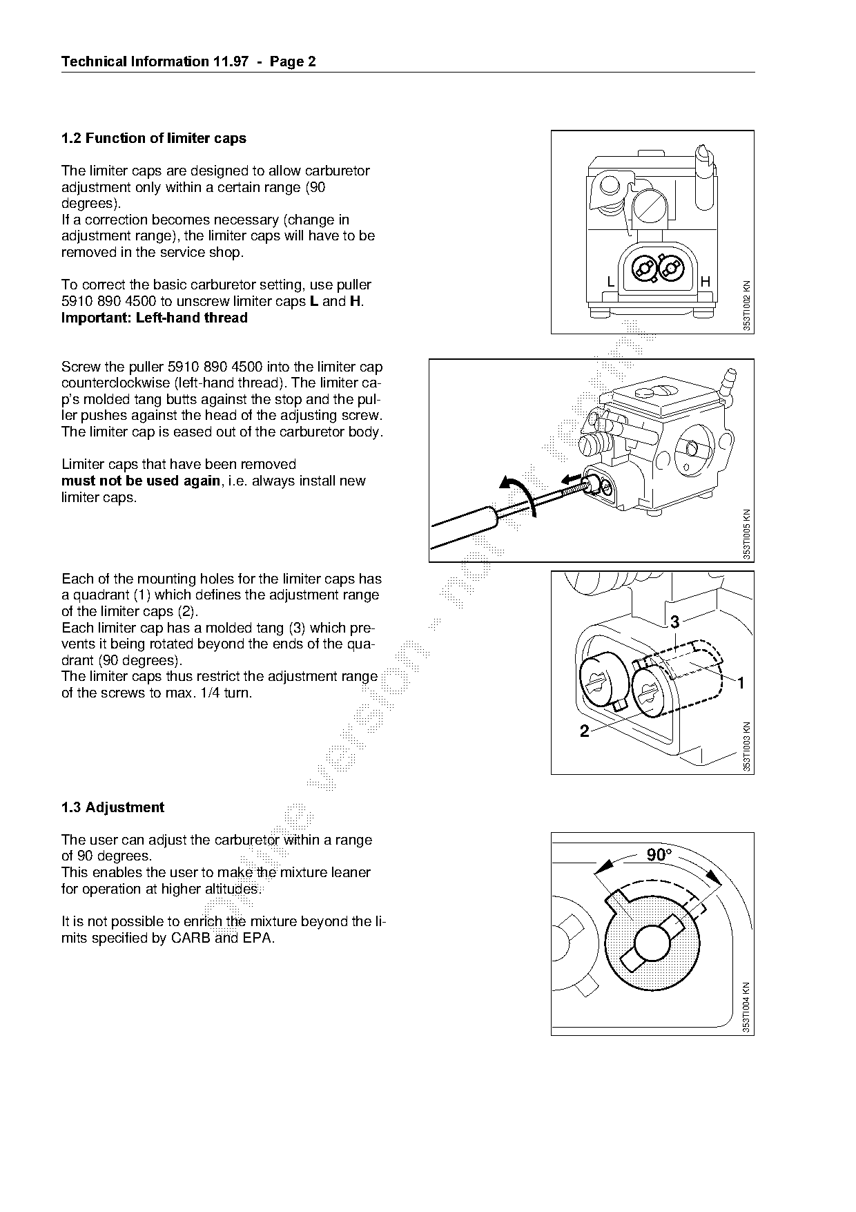
The limiter caps are designed to allow carburetor
adjustment only within a certain range (90
degrees).
If a correction becomes necessary (change in
adjustment range), the limiter caps will have to be
removed in the service shop.

To correct the basic carburetor setting, use puller                      L         H

                                                                                       353TI002 KN
5910 890 4500 to unscrew limiter caps / and +.
Important: Left-hand thread

Screw the puller 5910 890 4500 into the limiter cap
counterclockwise (left-hand thread). The limiter ca-
p’s molded tang butts against the stop and the pul-

ler pushes against the head of the adjusting screw.
The limiter cap is eased out of the carburetor body.

Limiter caps that have been removed
must not be used againI=iKeK=~lw~ys=inst~ll=new
limiter caps.

                                                                                       353TI005 KN

Each of the mounting holes for the limiter caps has

a quadrant (1) which defines the adjustment range
of the limiter caps (2).
Each limiter cap has a molded tang (3) which pre-                              3
vents it being rotated beyond the ends of the qua-

drant (90 degrees).
The limiter caps thus restrict the adjustment range                                    1

of the screws to max. 1/4 turn.

                                                                                        353TI003 KN
                                                                     2

1.3=Adjustment

The user can adjust the carburetor within a range

of 90 degrees.                                                               90°
This enables the user to make the mixture leaner
for operation at higher altitudes.

It is not possible to enrich the mixture beyond the li-
mits specified by CARB and EPA.
                                                                                       353TI004 KN
Page 3 of 7
Text of page 3 — search, copy, screen readers
Technical Information 11.97  -  Page 3

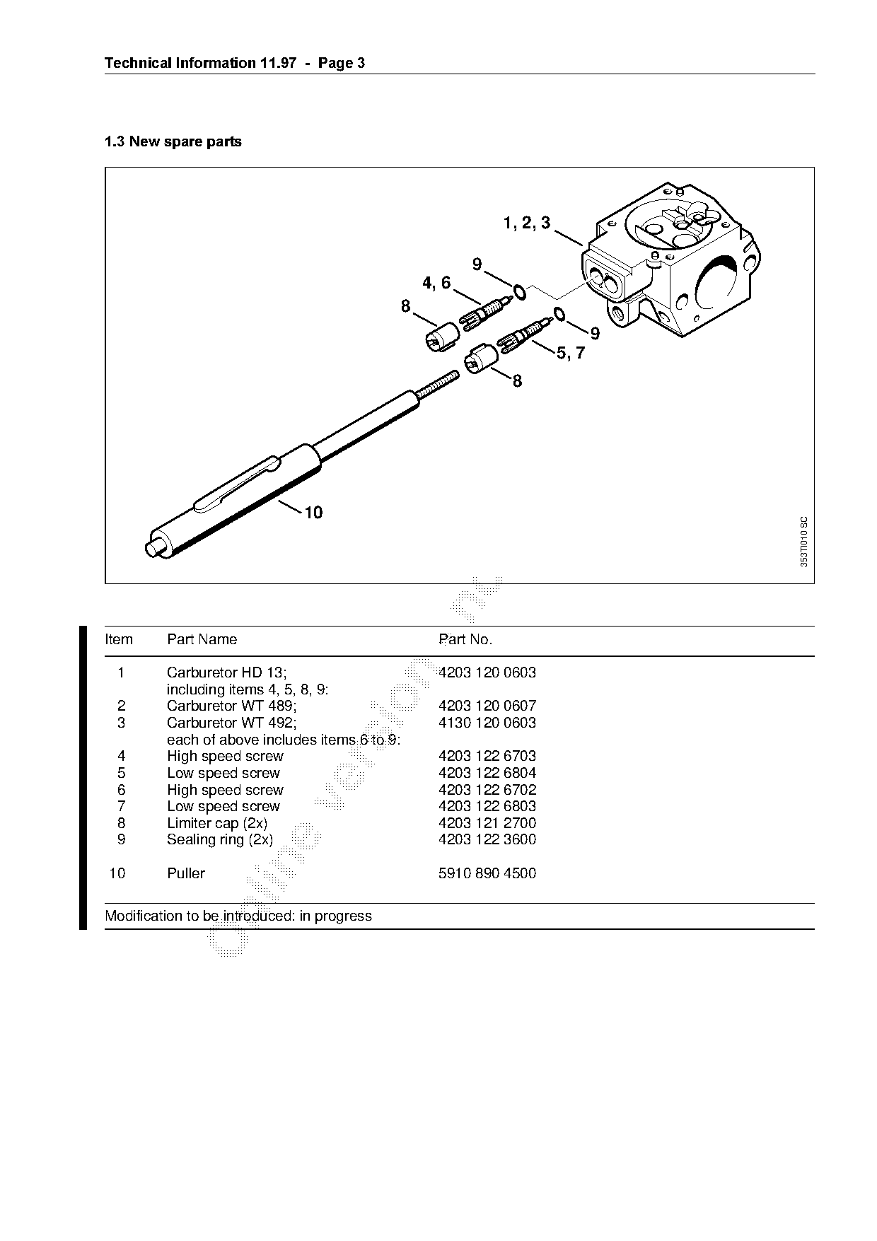
1.3=New spare parts

                                                                 1, 2, 3

                                                           9
                                                    4, 6
                                                8
                                                                                  9

                                                                           5, 7


                               10                              fo

                                                                                         353TI010 SC

Item     Part Name                                    Part No.

 1       Carburetor HD 13;                            4203 120 0603
         including items 4, 5, 8, 9:

 2       Carburetor WT 489;                           4203 120 0607
 3       Carburetor WT 492;                           4130 120 0603
         each of above includes items 6 to 9:
 4       High speed screw                             4203 122 6703

 5       Low speed screw                              4203 122 6804
 6       High speed screw                             4203 122 6702

 7       Low speed screw                              4203 122 6803
 8       Limiter cap (2x)                             4203 121 2700
 9       Sealing ring (2x)                            4203 122 3600

10       Puller                                       5910 890 4500

Modification to be introduced: in progress
Page 4 of 7
Text of page 4 — search, copy, screen readers
Technical Information 11.97  -  Page 4

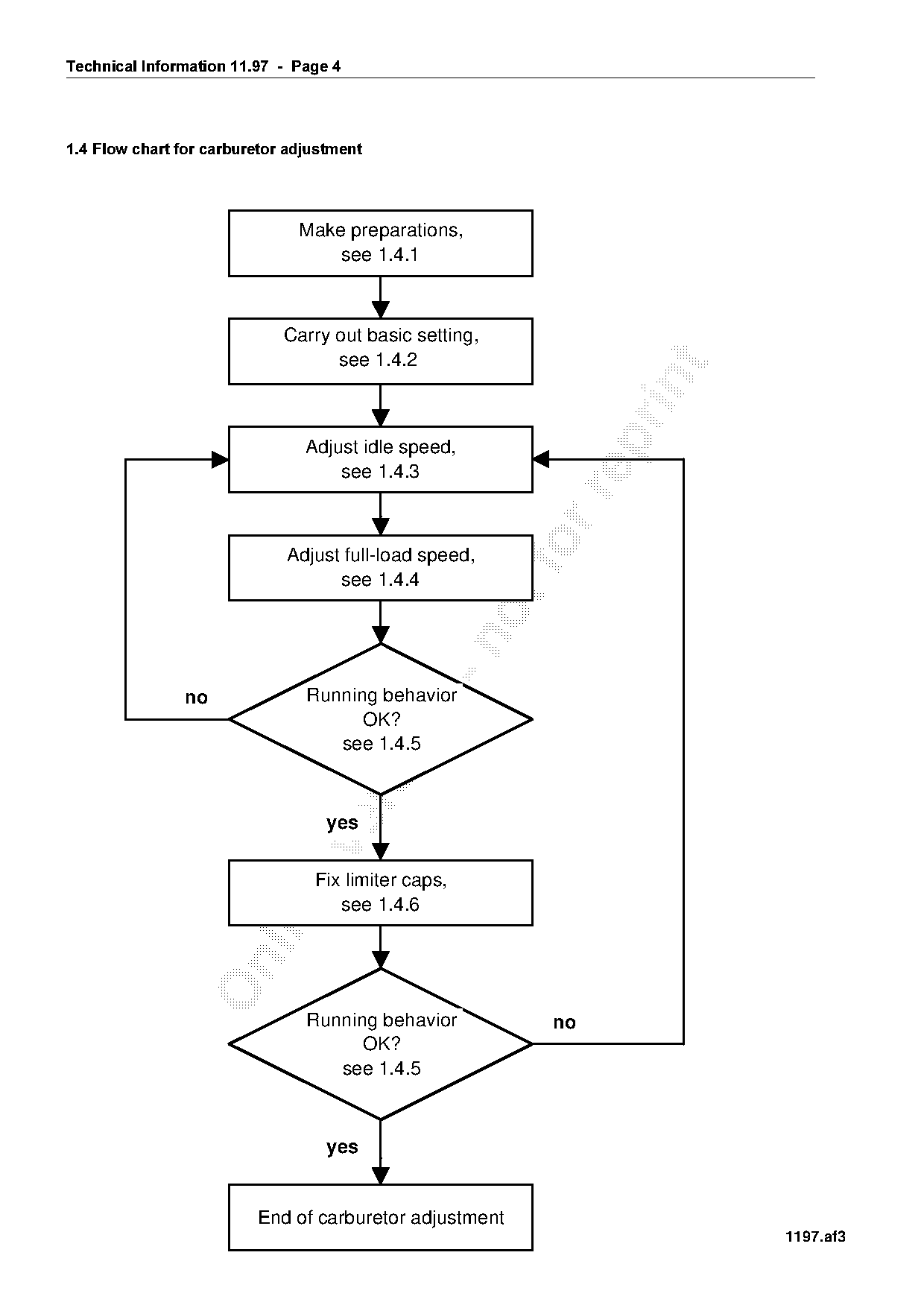
1.4=Flow chart for carburetor adjustment

                                Make preparations,
                                    see 1.4.1

                              Carry out basic setting,
                                    see 1.4.2

                                 Adjust idle speed,
                                     see 1.4.3

                              Adjust full-load speed,    fo
                                    see 1.4.4

                no               Running behavior

                                       OK?

                                    see 1.4.5

                                   yes

                                  Fix limiter caps,
                                     see 1.4.6

                                 Running behavior            no
                                       OK?
                                    see 1.4.5

                                   yes

                          End of carburetor adjustment
                                                                          1197.af3
Page 5 of 7
Text of page 5 — search, copy, screen readers
Technical Information 11.97  -  Page 5

1.4.1=Preparations

Engine speeds must be checked with a
tachometer.

• Check the air filter and clean if necessary.
• Inspect the spark arresting screen and clean
    or replace if necessary.

====On blowers
• Mount blower tubes and nozzle.
====On hedge trimmers

• Clean cutting blades and lubricate with oil.
====On brushcutters
• Mount STIHL Autocut or Polymatic head

    - adjust length of lines so that they extend as
    far as line limiting blade on the deflector.

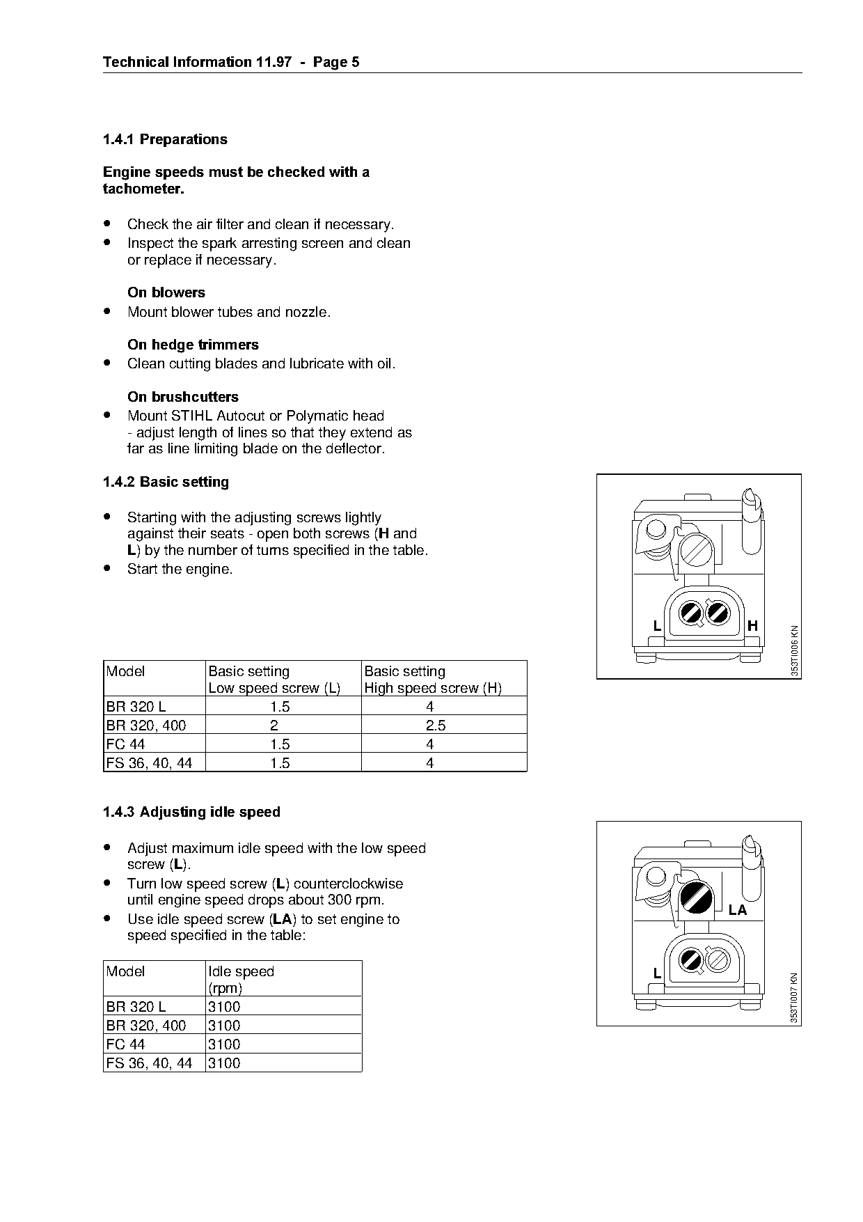
1.4.2=Basic setting

• Starting with the adjusting screws lightly
    against their seats - open both screws (+ and
    /) by the number of turns specified in the table.
•   Start the engine.

                                                                       L        H

                                                                                    353TI006 KN

Model            Basic setting             Basic setting

                 Low speed screw (L)       High speed screw (H)
BR 320 L                   1.5                       4
BR 320, 400                2                         2.5
FC 44                      1.5                       4

FS 36, 40, 44              1.5                       4

1.4.3=Adjusting idle speed

• Adjust maximum idle speed with the low speed

    screw (/).
•   Turn low speed screw (/) counterclockwise

    until engine speed drops about 300 rpm.
                                                                           LA
•   Use idle speed screw (/$) to set engine to
    speed specified in the table:

Model            Idle speed                                            L
                                                                                    353TI007 KN

                 (rpm)
BR 320 L         3100
BR 320, 400      3100
FC 44            3100
FS 36, 40, 44    3100
Page 6 of 7
Text of page 6 — search, copy, screen readers
Technical Information 11.97  -  Page 6

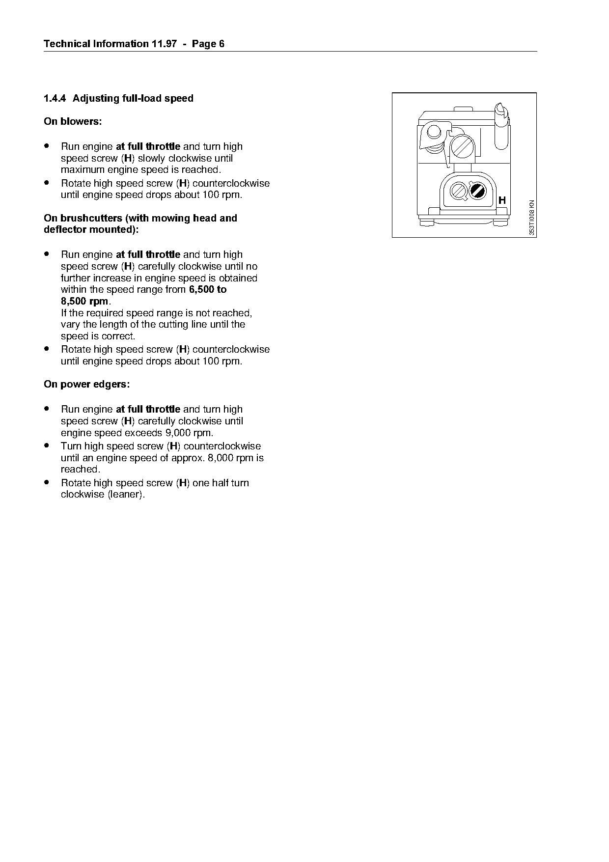
1.4.4= Adjusting full-load speed

On blowers

• Run engine at full throttle=~nd turn high
    speed screw (+) slowly clockwise until
    maximum engine speed is reached.
•   Rotate high speed screw (+) counterclockwise
    until engine speed drops about 100 rpm.
                                                                      H

                                                                          353TI008 KN
On brushcutters =with mowing head and
deflector mounted

• Run engine at full throttle=~nd turn high

    speed screw (+) carefully clockwise until no
    further increase in engine speed is obtained
====within=the=speed=r~nge=from=6,500 to

    8,500 rpm.
    If the required speed range is not reached,
    vary the length of the cutting line until the

    speed is correct.
•   Rotate high speed screw (+) counterclockwise
    until engine speed drops about 100 rpm.              fo
On power edgers
• Run engine at full throttle=~nd turn high
    speed screw (+) carefully clockwise until

    engine speed exceeds 9,000 rpm.
•   Turn high speed screw (+) counterclockwise
    until an engine speed of approx. 8,000 rpm is

    reached.
•   Rotate high speed screw (+) one half turn

    clockwise (leaner).
Page 7 of 7
Text of page 7 — search, copy, screen readers
Technical Information 11.97 - Page 7
1.4.5=Checking running behavior
• Open throttle several times and check that
engine accelerates smoothly -
the engine must also run smoothly at idle
speed.
1.4.6=Fixing limiter caps
• Always install QHZ limiter caps.
• Limiter caps that have been removed once
===must not be used again.
• Push the limiter caps into the adjusting screw
holes until they are flush with the carburetor
body.
2.=Setting instructions for user
These instructions are exactly the same as those
in the owner’s manual (chapter "Adjusting the
Carburetor"). fo
3.=Fuel =mix ratio
Emissions approval has been obtained with a
fuel-oil mix ratio of 50:1.
No emission measurements are available for other
mix ratios.
See also TI 41.94 and TI 47.94
4.=California Emission Control Warranty
6WDWHPHQW
See TI 41.94 and TI 47.94.
Last Technical Information on models
BR 320, 400: 14.96
FS 36, 40, 44: 19.96
FC 44: 07.96
1997 Andreas Stihl Andreas Stihl - D1/MTK-al
Technical Documentation 6000 Most of these PDFs embed fonts with a shifted character map, so the text above was recovered rather than copied — read it as a faithful but imperfect transcription, and treat the page image above each block as the authority where the two disagree — the figures exist only there, because they are vector drawings that text extraction cannot keep.