Technical Information · issue 37 of 1997
New master control for machines with looped handle
Model Serial No. fo
IssueTI 37/1997
From serial 36 941 204, 36 942 929
Full text
Page 1 of 5
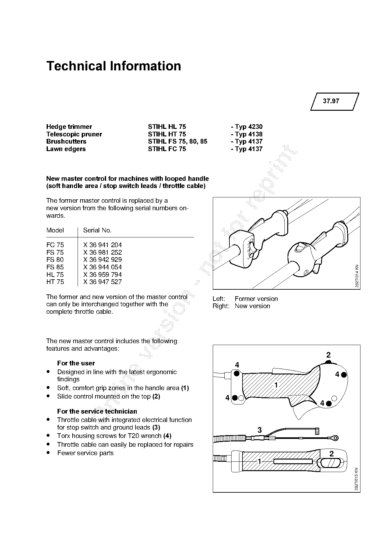
Text of page 1 — search, copy, screen readers
Technical Information

                                                                                   37.97

Hedge trimmer =======================STIHL HL 75==================- Typ 4230
Telescopic pruner====================STIHL HT 75==================- Typ 4138
Brushcutters=========================STIHL FS 75, 80, 85==========- Typ 4137
Lawn edgers =========================STIHL FC 75==================- Typ 4137

New master control for machines with looped handle

soft handle area / stop switch leads / throttle cable

The former master control is replaced by a

new version from the following serial numbers on-
wards.

Model        Serial No.                                     fo
FC 75        X 36 941 204
FS 75        X 36 981 252
FS 80        X 36 942 929

                                                                                                392TI014 KN
FS 85        X 36 944 054

HL 75        X 36 959 794
HT 75        X 36 947 527

The former and new version of the master control

                                                           Left: Former version
can only be interchanged together with the                 Right: New version

complete throttle cable.

The new master control includes the following
features and advantages:
                                                                                       2

====For the user===================================================Q
•   Designed in line with the latest ergonomic                                             4
    findings

•   Soft, comfort grip zones in the handle are~=1==============================N
•   Slide control mounted on the top 2========================Q
                                                                                   4

====For the service technician
•   Throttle cable with integrated electrical function
    for stop switch and ground leads 3====================================P
•   Torx housing screws for T20 wrench
•   Throttle cable can easily be replaced for repairs
•   Fewer service parts                                                                2
                                                                          1
                                                                                               392TI015 KN
Page 2 of 5
Text of page 2 — search, copy, screen readers
37.97 - 2

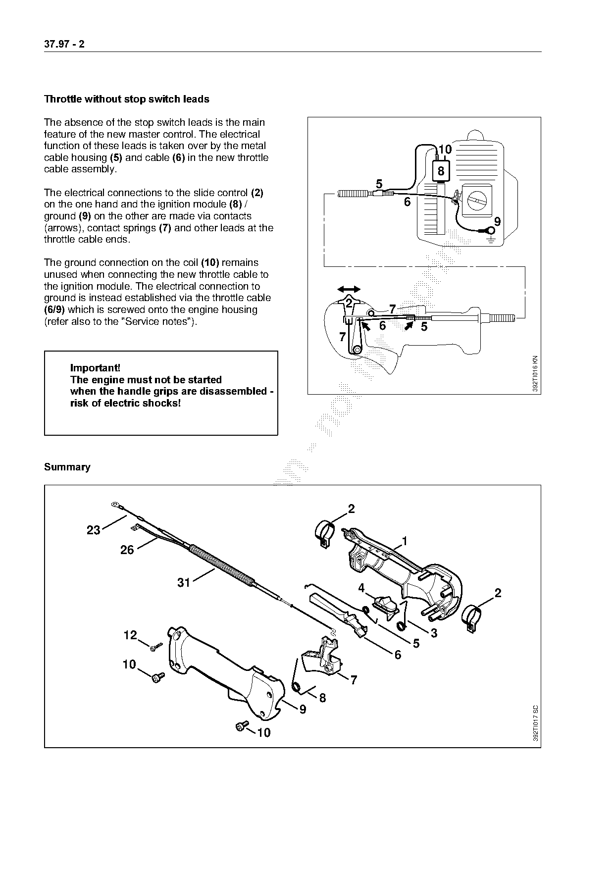
Throttle without stop switch leads

The absence of the stop switch leads is the main
feature of the new master control. The electrical
function of these leads is taken over by the metal                                                 10
cable housing 5=~nd cable 6=in the new throttle
cable assembly.                                                                                    8
                                                                           5
The electrical connections to the slide control
on the one hand and the ignition module 8=L========================================S
ground 9=on the other are made via contacts
(arrows), contact springs 7=~nd other leads at the                                                      9
throttle cable ends.

The ground connection on the coil 10=remains
unused when connecting the new throttle cable to
the ignition module. The electrical connection to

ground is instead established via the throttle cable
 6/9=which is screwed onto the engine housing
                                                               2               7
(refer also to the "Service notes").
                                                                           6               5


                                                                                                            392TI016 KN
      Important!
======The engine must not be started
======when the handle grips are disassembled -
======risk of electric shocks!

6XPPDU\

                                                                   2
            23

                                                                                   1
                 26

                              31                                       4                                2

                  12                                                                           3

                                                                                       5
                                                                               6
                 10
                                                                   7
                                                           8
                                                                                                            392TI017 SC

                                                       9
                                                10
Page 3 of 5
Text of page 3 — search, copy, screen readers
                                                                                       37.97 - 3

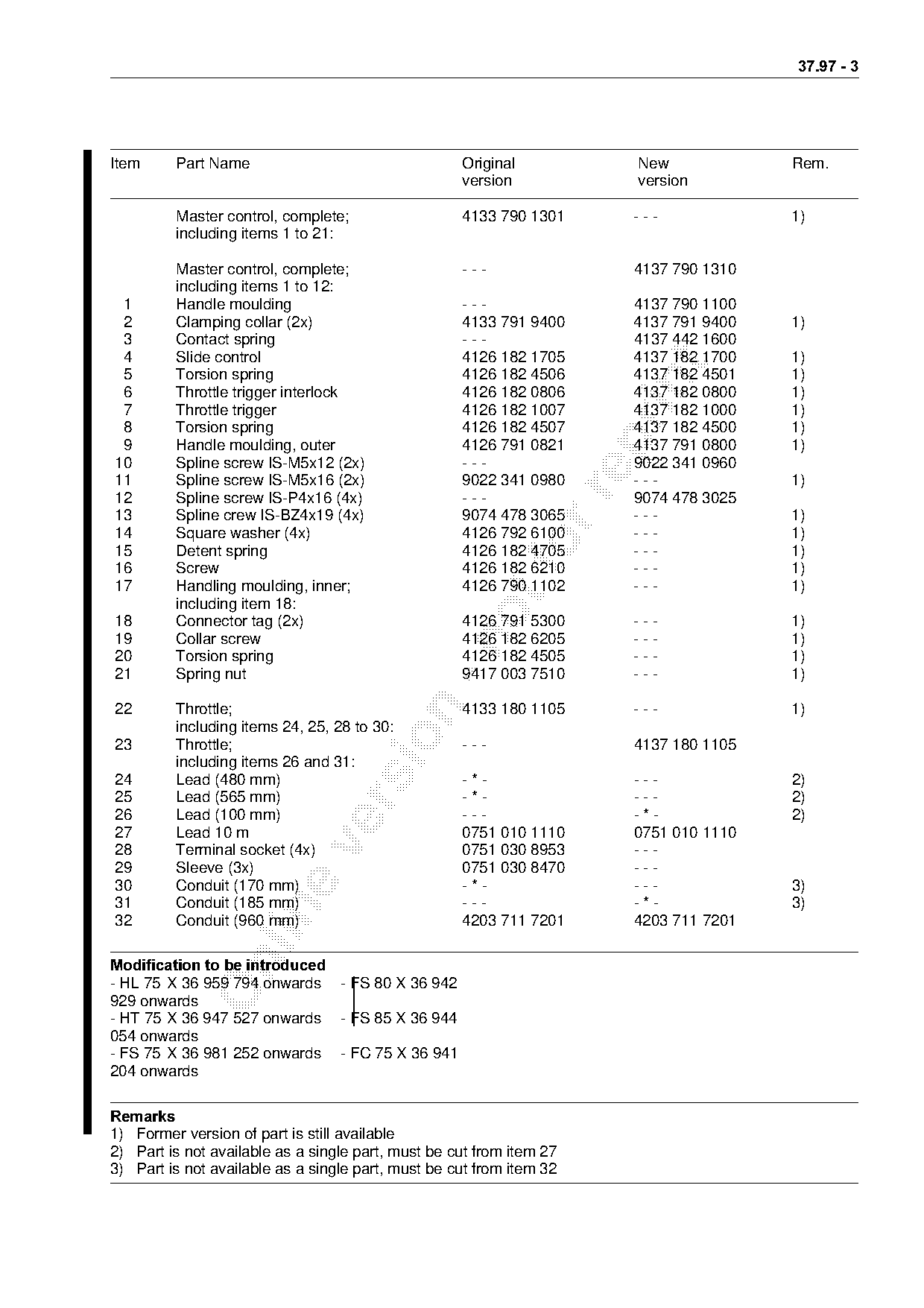
Item     Part Name                                  Original           New             Rem.
                                                    version            version

         Master control, complete;                  4133 790 1301      ---             1)
         including items 1 to 21:

         Master control, complete;                  ---                4137 790 1310
         including items 1 to 12:
 1       Handle moulding                            ---                4137 790 1100
 2       Clamping collar (2x)                       4133 791 9400      4137 791 9400   1)
 3       Contact spring                             ---                4137 442 1600
 4       Slide control                              4126 182 1705      4137 182 1700   1)

 5       Torsion spring                             4126 182 4506      4137 182 4501   1)

 6       Throttle trigger interlock                 4126 182 0806      4137 182 0800   1)
 7       Throttle trigger                           4126 182 1007      4137 182 1000   1)
 8       Torsion spring                             4126 182 4507      4137 182 4500   1)

 9       Handle moulding, outer                     4126 791 0821      4137 791 0800   1)
10       Spline screw IS-M5x12 (2x)                 ---                9022 341 0960
11       Spline screw IS-M5x16 (2x)                 9022 341 0980      ---             1)

12       Spline screw IS-P4x16 (4x)                 ---                9074 478 3025
13       Spline crew IS-BZ4x19 (4x)                 9074 478 3065      ---             1)
14       Square washer (4x)                         4126 792 6100      ---             1)
15
16
         Detent spring
         Screw
                                                    4126 182 4705
                                                    4126 182 6210
                                                                       ---
                                                                       ---
                                                                                       1)
                                                                                       1)
17       Handling moulding, inner;                  4126 790 1102      ---             1)
         including item 18:
18       Connector tag (2x)                         4126 791 5300      ---             1)
19       Collar screw                               4126 182 6205      ---             1)

20       Torsion spring                             4126 182 4505      ---             1)
21       Spring nut                                 9417 003 7510      ---             1)

22       Throttle;                                  4133 180 1105      ---             1)
         including items 24, 25, 28 to 30:

23       Throttle;                                  ---                4137 180 1105
         including items 26 and 31:
24       Lead (480 mm)                              -*-                ---             2)
25       Lead (565 mm)                              -*-                ---             2)

26       Lead (100 mm)                              ---                -*-             2)
27       Lead 10 m                                  0751 010 1110      0751 010 1110

28       Terminal socket (4x)                       0751 030 8953      ---
29       Sleeve (3x)                                0751 030 8470      ---
30       Conduit (170 mm)                           -*-                ---             3)
31       Conduit (185 mm)                           ---                -*-             3)

32       Conduit (960 mm)                           4203 711 7201      4203 711 7201

Modification to be introduced
- HL 75 X 36 959 794 onwards - FS 80 X 36 942
929 onwards
- HT 75 X 36 947 527 onwards - FS 85 X 36 944
054 onwards
- FS 75 X 36 981 252 onwards - FC 75 X 36 941
204 onwards

5HPDUNV
1) Former version of part is still available
2) Part is not available as a single part, must be cut from item 27
3) Part is not available as a single part, must be cut from item 32
Page 4 of 5
Text of page 4 — search, copy, screen readers
37.97 - 4

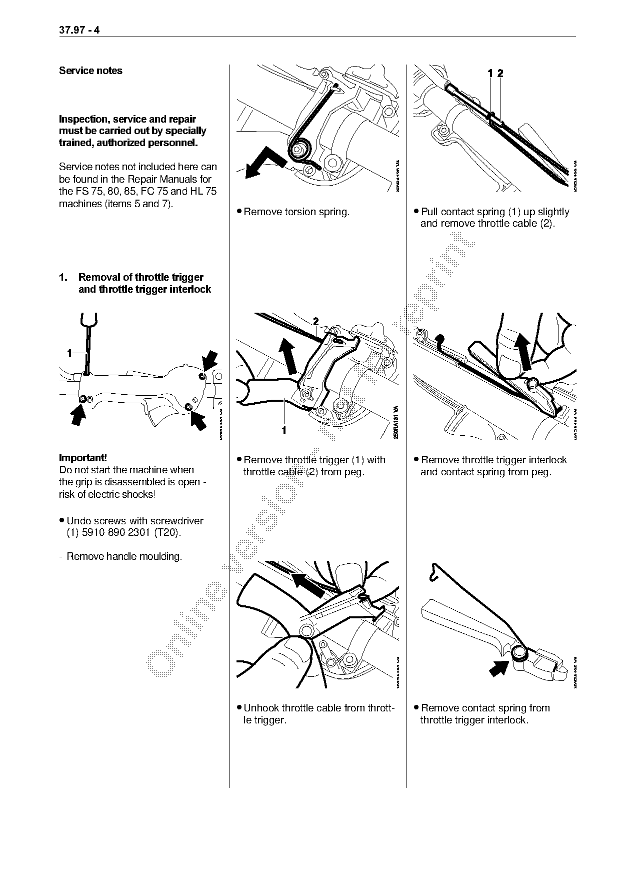
Service notes

Inspection, service and repair
must be carried out by specially
trained, authorized personnel.

Service notes not included here can
be found in the Repair Manuals for
the FS 75, 80, 85, FC 75 and HL 75
machines (items 5 and 7).
                                      • Remove torsion spring.               • Pull contact spring (1) up slightly
                                                                              and remove throttle cable (2).

1.===Removal of throttle trigger
=====and throttle trigger interlock

Important!============================• Remove throttle trigger (1) with     • Remove throttle trigger interlock
Do not start the machine when          throttle cable (2) from peg.           and contact spring from peg.

the grip is disassembled is open -

risk of electric shocks!

• Undo screws with screwdriver
 (1) 5910 890 2301 (T20).

- Remove handle moulding.

                                      • Unhook throttle cable from thrott-   • Remove contact spring from
                                       le trigger.                            throttle trigger interlock.
Page 5 of 5
Text of page 5 — search, copy, screen readers
37.97 - 5
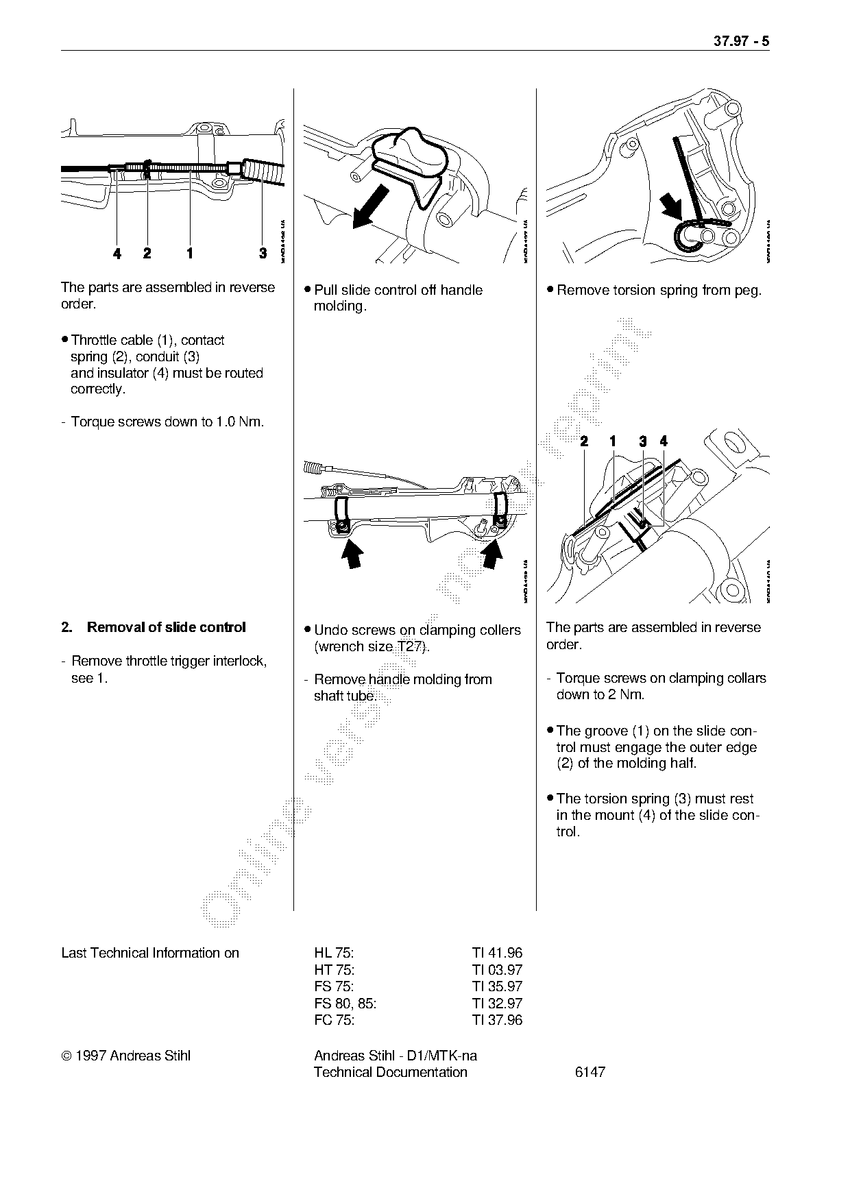
The parts are assembled in reverse • Pull slide control off handle • Remove torsion spring from peg.
order. molding.
• Throttle cable (1), contact
spring (2), conduit (3)
and insulator (4) must be routed
correctly.
- Torque screws down to 1.0 Nm.
2.===Removal of slide control==========• Undo screws on clamping collers The parts are assembled in reverse
(wrench size T27). order.
- Remove throttle trigger interlock,
see 1. - Remove handle molding from - Torque screws on clamping collars
shaft tube. down to 2 Nm.
• The groove (1) on the slide con-
trol must engage the outer edge
(2) of the molding half.
• The torsion spring (3) must rest
in the mount (4) of the slide con-
trol.
Last Technical Information on HL 75: TI 41.96
HT 75: TI 03.97
FS 75: TI 35.97
FS 80, 85: TI 32.97
FC 75: TI 37.96
1997 Andreas Stihl Andreas Stihl - D1/MTK-na
Technical Documentation 6147 Most of these PDFs embed fonts with a shifted character map, so the text above was recovered rather than copied — read it as a faithful but imperfect transcription, and treat the page image above each block as the authority where the two disagree — the figures exist only there, because they are vector drawings that text extraction cannot keep.