Technical Information · issue 44 of 1997
New clearing saws
IssueTI 44/1997
From serial 37 266 391
Full text
Page 1 of 10
Text of page 1 — search, copy, screen readers
Technical Information

                                                                                                       44.97

New STIHL FS 550 Clearing Saws - Series 4116

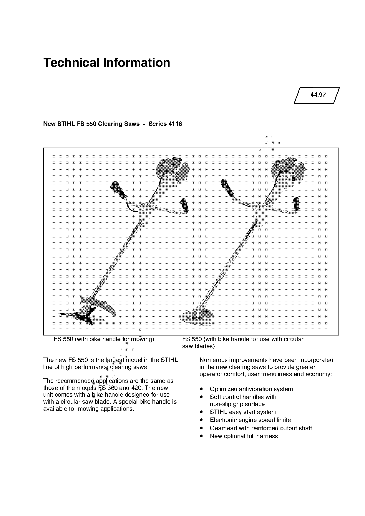
   FS 550 (with bike handle for mowing)               FS 550 (with bike handle for use with circular
                                                      saw blades)

The new FS 550 is the largest model in the STIHL            Numerous improvements have been incorporated
line of high performance clearing saws.                     in the new clearing saws to provide greater
                                                            operator comfort, user friendliness and economy:

The recommended applications are the same as
those of the models FS 360 and 420. The new                 • Optimized antivibration system
unit comes with a bike handle designed for use              • Soft control handles with
with a circular saw blade. A special bike handle is             non-slip grip surface
available for mowing applications.
                                                            •   STIHL easy start system
                                                            •   Electronic engine speed limiter
                                                            •   Gearhead with reinforced output shaft
                                                            •   New optional full harness
Page 2 of 10
Text of page 2 — search, copy, screen readers
44.97 - 2

Contents

1.   Technical Description
2.   Specifications
3.   Cutting Tools
4.   Special Accessories for Users
5.   Service Accessories
6.   Repairs
7.   Spare Parts

The following chapters only refer to the
differences over the previous models FS 360
and FS 420.

1. Technical Description

Cylinder
• Decompression valve.

Ignition system
• New ignition module with integral electronic
    speed limiter.

Harness
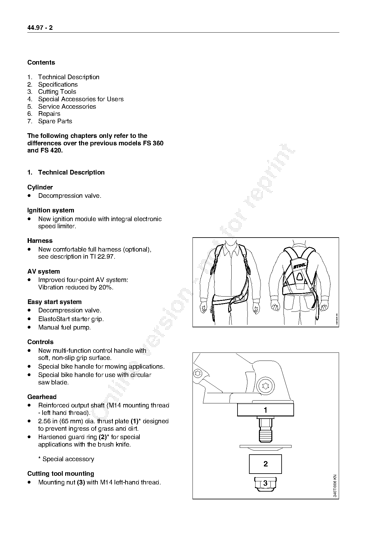
• New comfortable full harness (optional),
   see description in TI 22.97.

AV system
• Improved four-point AV system:
   Vibration reduced by 20%.

Easy start system

• Decompression valve.
• ElastoStart starter grip.

                                                                              002TI024 KN
• Manual fuel pump.

Controls
• New multi-function control handle with

   soft, non-slip grip surface.
• Special bike handle for mowing applications.
• Special bike handle for use with circular

   saw blade.

Gearhead

• Reinforced output shaft (M14 mounting thread
   - left hand thread).                                        1
• 2.56 in (65 mm) dia. thrust plate (1)* designed
   to prevent ingress of grass and dirt.
• Hardened guard ring (2)* for special
   applications with the brush knife.

     * Special accessory
                                                               2
Cutting tool mounting
                                                                      340TI006 KN

• Mounting nut (3) with M14 left-hand thread.                  3
Page 3 of 10
Text of page 3 — search, copy, screen readers
                                                                                    44.97 - 3

2. Specifications

2.1 Powerhead

2.1.1 Engine
                                  FS 550

Displacement:                     3.45 cu.in (56.5 cc)
Bore:                             1.81 in (46 mm)
Stroke:                           1.34 in (34 mm)
Engine power to ISO 8893:      3.8 bhp (2.8 kW)
Idle speed:                       2,500 rpm
Cut-off speed without

cutting tool

(electronic speed limiter):    12,500 rpm (+/- 800 rpm)
Max. output shaft speed
(rated):                          9,400 rpm

Rewind starter:                   Single pawl system;
                                  ElastoStart grip
Starter rope:                     0.14 in dia. (3.5 mm)

Clutch:
- Clutch engages at:           3,250 rpm

2.1.2 Fuel system
HD 22 carburetor with limiter caps
(for compliance with EPA regulations - see

TI 27.97)

Limiter caps are fitted on the high speed and the
low speed screws of the carburetor to restrict

the range of adjustment. The heads of the
adjusting

screws are knurled to take the caps.

The limiter caps are pushed on to the heads of
the adjusting screws and held in position by the

knurling. Once installed, the caps are flush with
the casting.

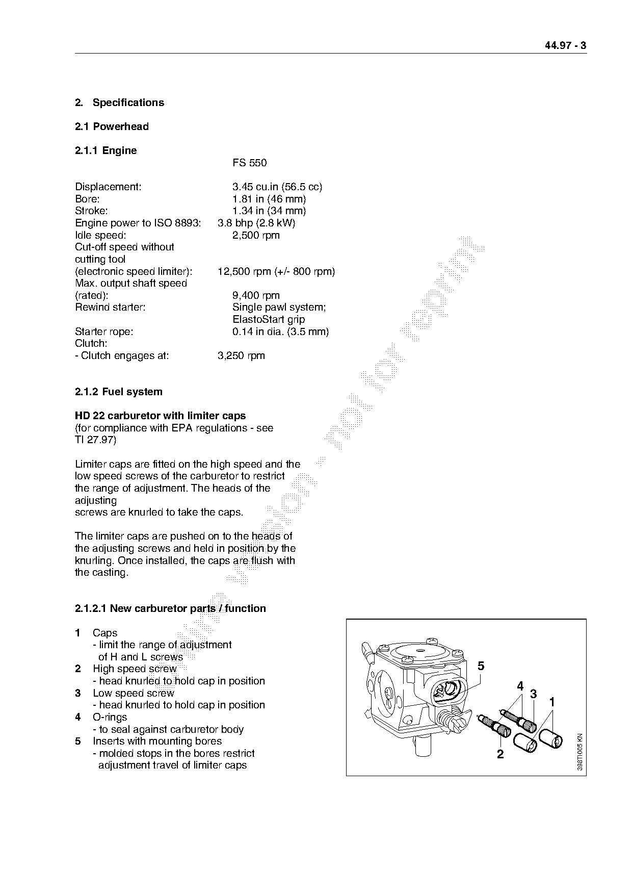
2.1.2.1 New carburetor parts / function

1   Caps
    - limit the range of adjustment
      of H and L screws

2   High speed screw                                                5
    - head knurled to hold cap in position
3   Low speed screw
                                                                            4
                                                                                3
    - head knurled to hold cap in position                                          1
4   O-rings
    - to seal against carburetor body
                                                                                           398TI005 KN

5   Inserts with mounting bores
    - molded stops in the bores restrict                                2
      adjustment travel of limiter caps
Page 4 of 10
Text of page 4 — search, copy, screen readers
44.97 - 4

2.1.2.2 Standard setting

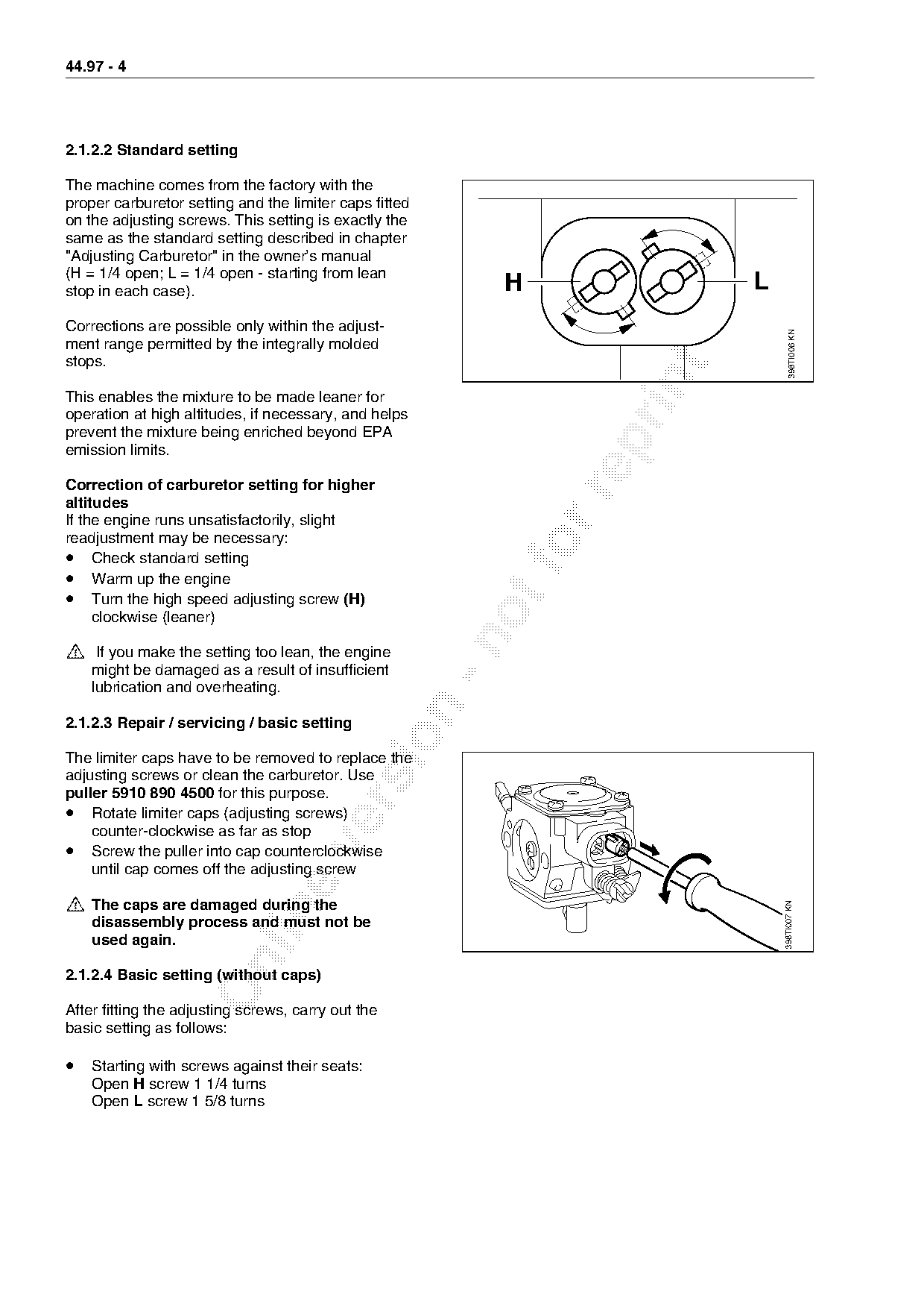
The machine comes from the factory with the
proper carburetor setting and the limiter caps fitted
on the adjusting screws. This setting is exactly the
same as the standard setting described in chapter
"Adjusting Carburetor" in the owner’s manual
(H = 1/4 open; L = 1/4 open - starting from lean
stop in each case).                                      H                L
Corrections are possible only within the adjust-

                                                                                 398TI006 KN
ment range permitted by the integrally molded
stops.

This enables the mixture to be made leaner for
operation at high altitudes, if necessary, and helps
prevent the mixture being enriched beyond EPA

emission limits.

Correction of carburetor setting for higher

altitudes
If the engine runs unsatisfactorily, slight
readjustment may be necessary:
• Check standard setting
• Warm up the engine
• Turn the high speed adjusting screw (H)
     clockwise (leaner)

!

     If you make the setting too lean, the engine
    might be damaged as a result of insufficient
    lubrication and overheating.

2.1.2.3 Repair / servicing / basic setting

The limiter caps have to be removed to replace the
adjusting screws or clean the carburetor. Use
puller 5910 890 4500 for this purpose.

• Rotate limiter caps (adjusting screws)
    counter-clockwise as far as stop
• Screw the puller into cap counterclockwise

    until cap comes off the adjusting screw

!   The caps are damaged during the
                                                                              398TI007 KN

    disassembly process and must not be
    used again.

2.1.2.4 Basic setting (without caps)

After fitting the adjusting screws, carry out the
basic setting as follows:

• Starting with screws against their seats:
    Open H screw 1 1/4 turns
    Open L screw 1 5/8 turns
Page 5 of 10
Text of page 5 — search, copy, screen readers
                                                                          44.97 - 5

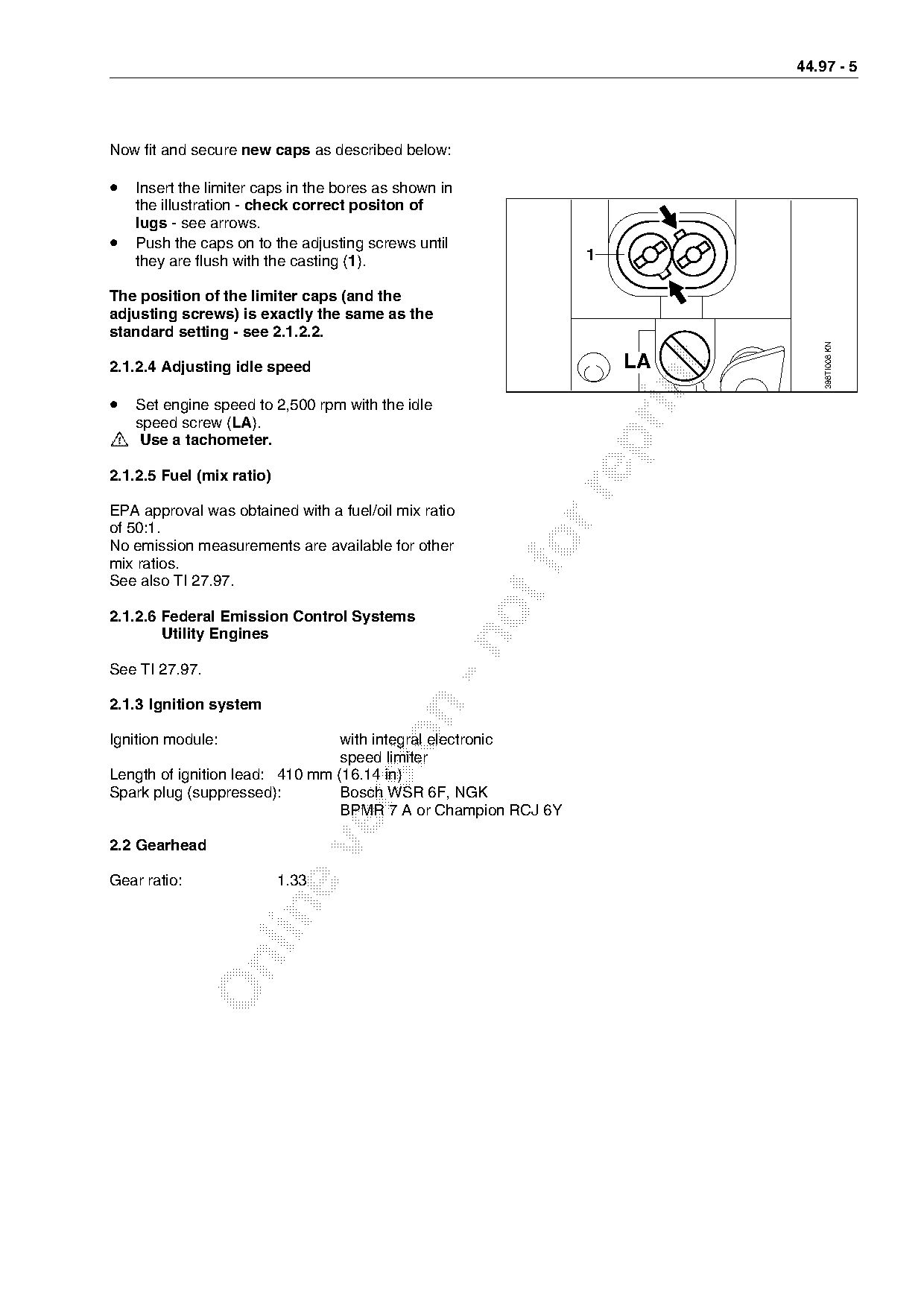
Now fit and secure new caps as described below:

• Insert the limiter caps in the bores as shown in
    the illustration - check correct positon of
    lugs - see arrows.
•   Push the caps on to the adjusting screws until
    they are flush with the casting (1).                       1

The position of the limiter caps (and the
adjusting screws) is exactly the same as the
standard setting - see 2.1.2.2.

                                                                              398TI008 KN
                                                                   LA

2.1.2.4 Adjusting idle speed

• Set engine speed to 2,500 rpm with the idle
!   speed screw (LA).

     Use a tachometer.

2.1.2.5 Fuel (mix ratio)

EPA approval was obtained with a fuel/oil mix ratio
of 50:1.
No emission measurements are available for other
mix ratios.
See also TI 27.97.
2.1.2.6 Federal Emission Control Systems
        Utility Engines

See TI 27.97.

2.1.3 Ignition system

Ignition module:                 with integral electronic
                                 speed limiter
Length of ignition lead: 410 mm (16.14 in)
Spark plug (suppressed):         Bosch WSR 6F, NGK

                                 BPMR 7 A or Champion RCJ 6Y

2.2 Gearhead

Gear ratio:                1.33
Page 6 of 10
Text of page 6 — search, copy, screen readers
44.97 - 6

2.3 Weight

                                               FS 550
without cutting tool and deflector             21.6 lbs (9.8 kg)

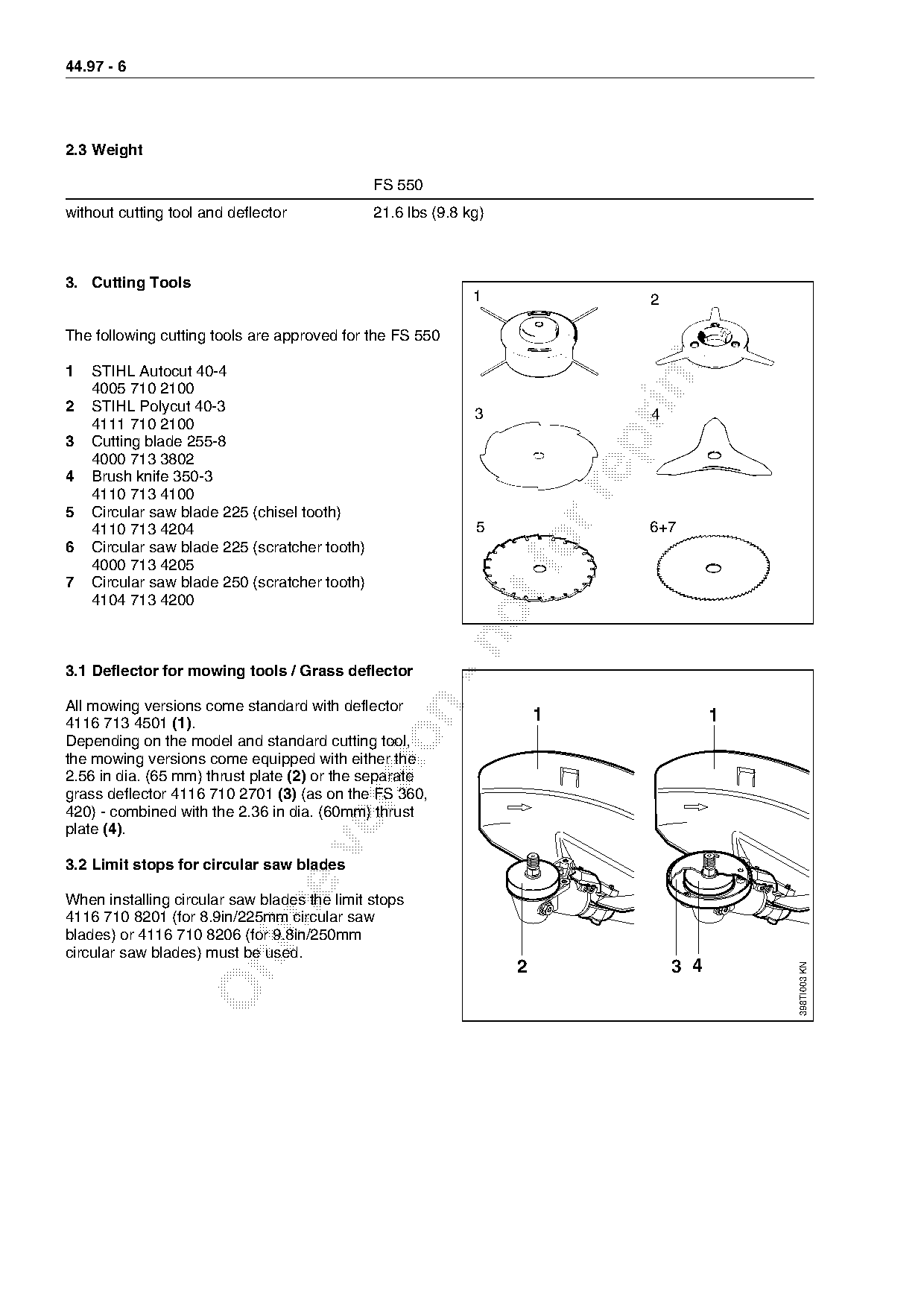
3. Cutting Tools
                                                              1                 2

The following cutting tools are approved for the FS 550

1   STIHL Autocut 40-4

    4005 710 2100
2   STIHL Polycut 40-3                                        3                 4
    4111 710 2100

3   Cutting blade 255-8
    4000 713 3802
4   Brush knife 350-3

    4110 713 4100
5   Circular saw blade 225 (chisel tooth)
    4110 713 4204                                             5                 6+7
6   Circular saw blade 225 (scratcher tooth)
    4000 713 4205
7   Circular saw blade 250 (scratcher tooth)
    4104 713 4200

3.1 Deflector for mowing tools / Grass deflector

All mowing versions come standard with deflector

4116 713 4501 (1).                                                     1                  1

Depending on the model and standard cutting tool,
the mowing versions come equipped with either the
2.56 in dia. (65 mm) thrust plate (2) or the separate
grass deflector 4116 710 2701 (3) (as on the FS 360,

420) - combined with the 2.36 in dia. (60mm) thrust
plate (4).

3.2 Limit stops for circular saw blades

When installing circular saw blades the limit stops

4116 710 8201 (for 8.9in/225mm circular saw
blades) or 4116 710 8206 (for 9.8in/250mm
circular saw blades) must be used.

                                                                   2                3 4
                                                                                              398TI003 KN
Page 7 of 10
Text of page 7 — search, copy, screen readers
                                                                                                        44.97 - 7

4. Special Accessories for Users

Part Name                            Part No.        Application, Remarks
Transport guard for
metal cutting tools                  4116 790 3900   Cutting blade 255-8, brush knife 350-3
                                                     circular saw blade 225, 250 (scratcher and chisel tooth)
                                     4119 790 3906   Cutting blade 255-8, circular saw blade 225, 250
                                                     (scratcher tooth and chisel tooth)

Deflector                            4116 710 8105   "Shredder" deflector for special cutting applications
                                                     with the brush knife
Guard plate kit                      4116 007 1012   Protects underside of powerhead from damage

STIHL gear lubricant                                 Drive shaft in drive tube
- 3 oz (80 g) tube                   0781 120 1109
STIHL gear lubricant                                 Gearhead

- 3 oz (80 g) tube                   0781 120 1117

4.1 Nylon line for cutting heads

Line diameter                        For use with
/ color                                                      fo
0.095" orange               Autocut 40-4, Polycut 40-3
0.105" red            Polycut 40-3

4.2 Sharpening aids for metal cutting tools

Part Name                            Part No.        Application

Saw set                              4020 893 5000   Circular saw blade 225 (chisel tooth)

Sharpening template                  4020 890 5500   Brush knife

5. Service Accessories

5.1 Special servicing tools

Special servicing tools are listed in the service manual for model FS 550.
Page 8 of 10
Text of page 8 — search, copy, screen readers
44.97 - 8

5.2 Servicing aids

Part Name                           Part No.               Application                                      Rem.
Carburetor parts kit                      4116 007 1061          Walbro HD 22, HD 23
Set of gaskets                      4116 007 1051

Lubricating grease
(13 oz/370 g tube)                  0781 120 1111          Oil seals

6. Repairs

Note: If the unit is started up in the course of repairs or maintenance work, it is essential to strictly
observe all local and national safety regulations and the safety precautions outlined in the
owner’s manual.
A service manual is available for servicing and repair procedures.

The service manual does not include the chapters "Servicing the Carburetor", "Troubleshooting" or
any repairs involving standard procedures. Such repairs are described in separate handbooks.

6.1 Adjustments

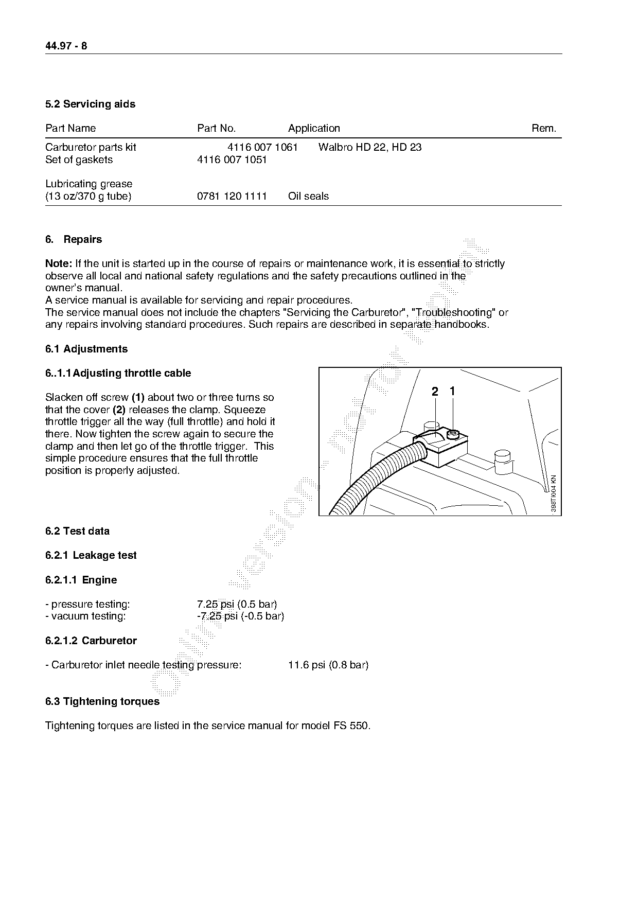
6..1.1Adjusting throttle cable

Slacken off screw (1) about two or three turns so
                                                                          fo           2 1
that the cover (2) releases the clamp. Squeeze
throttle trigger all the way (full throttle) and hold it
there. Now tighten the screw again to secure the

clamp and then let go of the throttle trigger. This
simple procedure ensures that the full throttle
position is properly adjusted.

                                                                                                               398TI004 KN

6.2 Test data

6.2.1 Leakage test

6.2.1.1 Engine

- pressure testing:                 7.25 psi (0.5 bar)
- vacuum testing:                   -7.25 psi (-0.5 bar)

6.2.1.2 Carburetor

- Carburetor inlet needle testing pressure:                11.6 psi (0.8 bar)

6.3 Tightening torques

Tightening torques are listed in the service manual for model FS 550.
Page 9 of 10
Text of page 9 — search, copy, screen readers
                                                                                               44.97 - 9

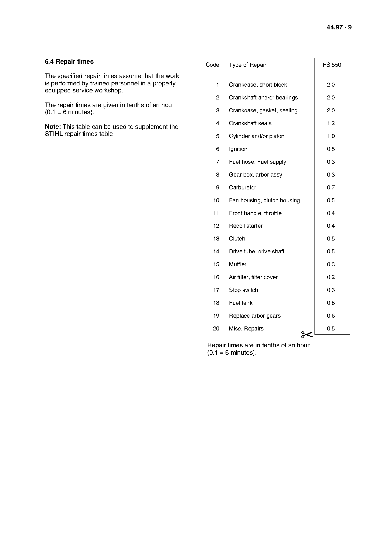
6.4 Repair times
                                                   Code     Type of Repair                    FS 550
The specified repair times assume that the work
is performed by trained personnel in a properly        1    Crankcase, short block             2.0
equipped service workshop.
                                                       2    Crankshaft and/or bearings         2.0
The repair times are given in tenths of an hour
(0.1 = 6 minutes).                                     3    Crankcase, gasket, sealing         2.0

                                                       4    Crankshaft seals                   1.2
Note: This table can be used to supplement the
STIHL repair times table.                              5    Cylinder and/or piston             1.0

                                                       6    Ignition                           0.5

                                                       7    Fuel hose, Fuel supply             0.3

                                                       8    Gear box, arbor assy               0.3

                                                       9    Carburetor                         0.7

                                                       10   Fan housing, clutch housing        0.5

                                                       11   Front handle, throttle             0.4

                                                       12   Recoil starter                     0.4

                                                       13   Clutch                             0.5
                                                       14   Drive tube, drive shaft            0.5

                                                       15   Muffler                            0.3

                                                       16   Air filter, filter cover           0.2

                                                       17   Stop switch                        0.3

                                                       18   Fuel tank                          0.8

                                                       19   Replace arbor gears                0.6

                                                       20   Misc. Repairs                      0.5

                                                                                          ✂
                                                   Repair times are in tenths of an hour

                                                   (0.1 = 6 minutes).
Page 10 of 10
Text of page 10 — search, copy, screen readers
44.97 - 10

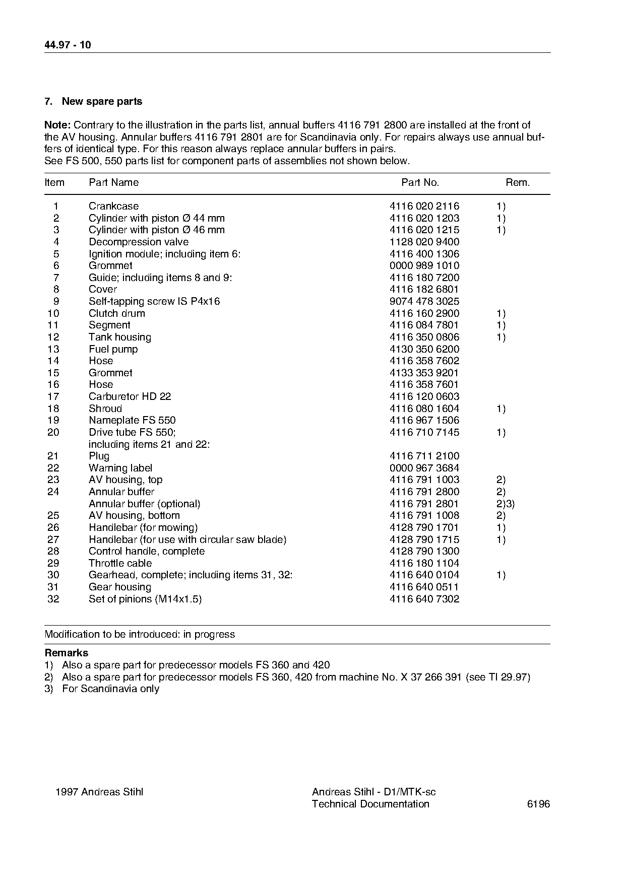
7. New spare parts

Note: Contrary to the illustration in the parts list, annual buffers 4116 791 2800 are installed at the front of
the AV housing. Annular buffers 4116 791 2801 are for Scandinavia only. For repairs always use annual buf-
fers of identical type. For this reason always replace annular buffers in pairs.
See FS 500, 550 parts list for component parts of assemblies not shown below.

Item     Part Name                                                             Part No.                Rem.

 1       Crankcase                                                           4116 020 2116           1)
 2       Cylinder with piston Ø 44 mm                                        4116 020 1203           1)
 3       Cylinder with piston Ø 46 mm                                        4116 020 1215           1)
 4       Decompression valve                                                 1128 020 9400

 5       Ignition module; including item 6:                                  4116 400 1306

 6       Grommet                                                             0000 989 1010
 7       Guide; including items 8 and 9:                                     4116 180 7200
 8       Cover                                                               4116 182 6801

 9       Self-tapping screw IS P4x16                                         9074 478 3025
10       Clutch drum                                                         4116 160 2900           1)
11       Segment                                                             4116 084 7801           1)

12       Tank housing                                                        4116 350 0806           1)
13       Fuel pump                                                           4130 350 6200
14       Hose                                                                4116 358 7602
15
16
         Grommet
         Hose
                                                                    fo       4133 353 9201
                                                                             4116 358 7601
17       Carburetor HD 22                                                    4116 120 0603
18       Shroud                                                              4116 080 1604           1)
19       Nameplate FS 550                                                    4116 967 1506
20       Drive tube FS 550;                                                  4116 710 7145           1)

         including items 21 and 22:
21       Plug                                                                4116 711 2100
22       Warning label                                                       0000 967 3684

23       AV housing, top                                                     4116 791 1003           2)
24       Annular buffer                                                      4116 791 2800           2)

         Annular buffer (optional)                                           4116 791 2801           2)3)
25       AV housing, bottom                                                  4116 791 1008           2)
26       Handlebar (for mowing)                                              4128 790 1701           1)
27       Handlebar (for use with circular saw blade)                         4128 790 1715           1)

28       Control handle, complete                                            4128 790 1300
29       Throttle cable                                                      4116 180 1104

30       Gearhead, complete; including items 31, 32:                         4116 640 0104           1)
31       Gear housing                                                        4116 640 0511
32       Set of pinions (M14x1.5)                                            4116 640 7302

Modification to be introduced: in progress

Remarks
1) Also a spare part for predecessor models FS 360 and 420
2) Also a spare part for predecessor models FS 360, 420 from machine No. X 37 266 391 (see TI 29.97)
3) For Scandinavia only

  1997 Andreas Stihl                                       Andreas Stihl - D1/MTK-sc
                                                           Technical Documentation                          6196
Most of these PDFs embed fonts with a shifted character map, so the text above was recovered rather than copied — read it as a faithful but imperfect transcription, and treat the page image above each block as the authority where the two disagree — the figures exist only there, because they are vector drawings that text extraction cannot keep.