Technical Information · issue 46 of 1997
Uprated engine; 029 SUPER; air filter/carburetor;
Model 029 chainsaws are being manufactured
IssueTI 46/1997
Engine family 1127
Part changes (1)
| Was | Becomes | What the bulletin says |
|---|---|---|
| 1127 120 1611 | 1127 120 1621 | The original air filter 1127 120 1611 will be 1 replaced by the new version 1127 120 1621 (with stub for connecting the compensator). |
Full text
Page 1 of 8
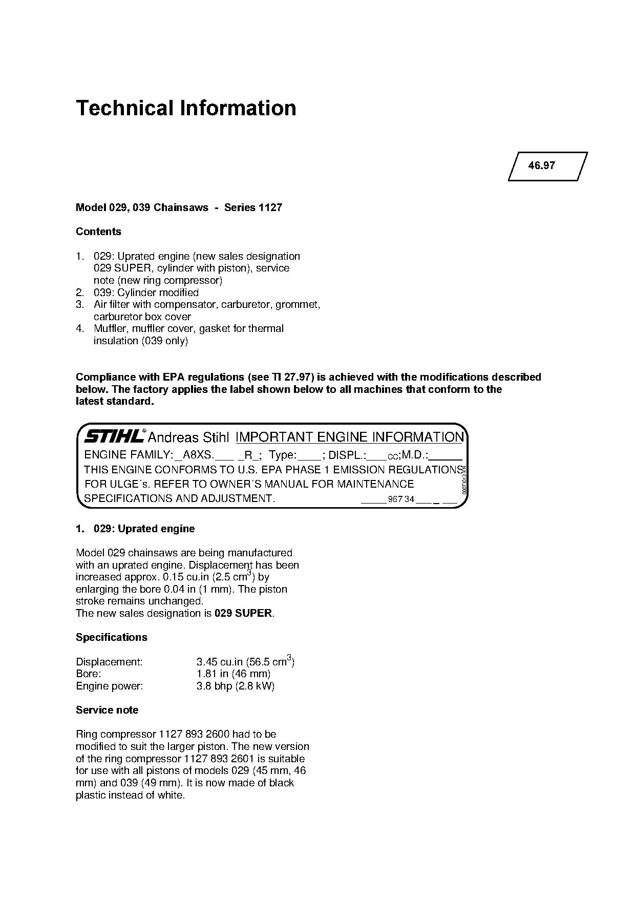
Text of page 1 — search, copy, screen readers
Technical Information

                                                                                         46.97

Model 029, 039 Chainsaws  -  Series 1127

&RQWHQWV

1. 029: Uprated engine (new sales designation
   029 SUPER, cylinder with piston), service
   note (new ring compressor)
2. 039: Cylinder modified
3. Air filter with compensator, carburetor, grommet,
   carburetor box cover
4. Muffler, muffler cover, gasket for thermal
   insulation (039 only)

Compliance with EPA regulations =see TI 27.97= is achieved with the modifications described
below. The factory applies the label shown below to all machines that conform to the
latest standard.

                Andreas Stihl IMPORTANT ENGINE INFORMATION
 ENGINE FAMILY: A8XS.     R ; Type:    ; DISPL.:   CC;M.D.:
 THIS ENGINE CONFORMS TO U.S. EPA PHASE 1 EMISSION REGULATIONS
                                                                           000TI013 KN

 FOR ULGE´s. REFER TO OWNER´S MANUAL FOR MAINTENANCE
 SPECIFICATIONS AND ADJUSTMENT.                    967 34

1.=029: Uprated engine

Model 029 chainsaws are being manufactured
with an uprated engine. Displacement has been
increased approx. 0.15 cu.in (2.5 cm3) by
enlarging the bore 0.04 in (1 mm). The piston
stroke remains unchanged.
The new sales designation is 029 SUPER.

6SHFLILFDWLRQV

Displacement:             3.45 cu.in (56.5 cm3)
Bore:                     1.81 in (46 mm)
Engine power:             3.8 bhp (2.8 kW)

Service note

Ring compressor 1127 893 2600 had to be
modified to suit the larger piston. The new version
of the ring compressor 1127 893 2601 is suitable
for use with all pistons of models 029 (45 mm, 46
mm) and 039 (49 mm). It is now made of black
plastic instead of white.
Page 2 of 8
Text of page 2 — search, copy, screen readers
46.97 - 2

6XPPDU\

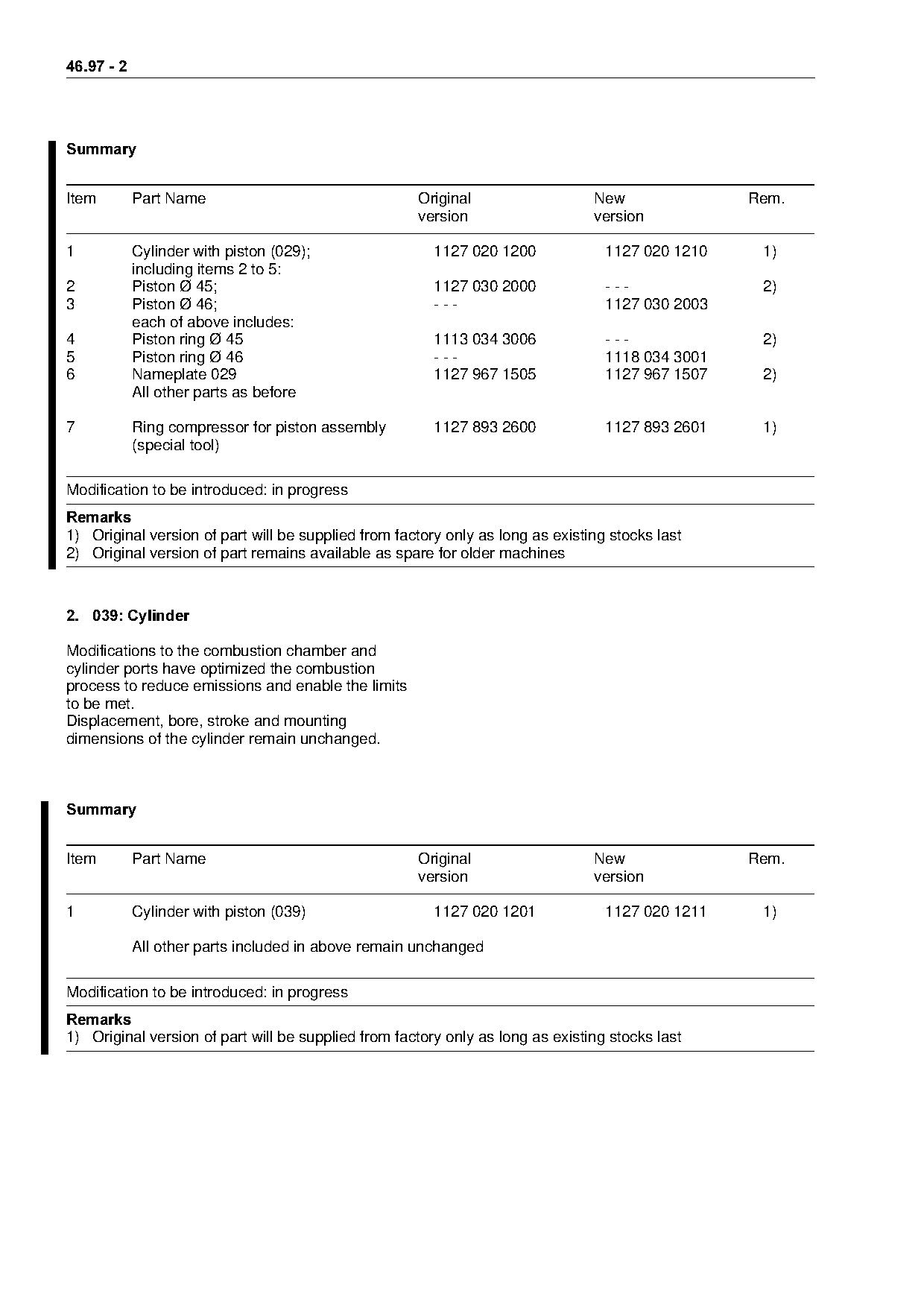
Item        Part Name                                Original                   New               Rem.
                                                     version                    version

1           Cylinder with piston (029);                 1127 020 1200             1127 020 1210    1)
            including items 2 to 5:
2           Piston Ø 45;                                1127 030 2000             ---              2)
3           Piston Ø 46;                                ---                       1127 030 2003
            each of above includes:
4           Piston ring Ø 45                            1113 034 3006             ---              2)
5           Piston ring Ø 46                            ---                       1118 034 3001
6           Nameplate 029                               1127 967 1505             1127 967 1507    2)
            All other parts as before

7           Ring compressor for piston assembly         1127 893 2600             1127 893 2601    1)
            (special tool)

Modification to be introduced: in progress
5HPDUNV
1) Original version of part will be supplied from factory only as long as existing stocks last
2) Original version of part remains available as spare for older machines

2.=039: Cylinder

Modifications to the combustion chamber and
cylinder ports have optimized the combustion
process to reduce emissions and enable the limits
to be met.
Displacement, bore, stroke and mounting
dimensions of the cylinder remain unchanged.

6XPPDU\

Item        Part Name                                Original                   New               Rem.
                                                     version                    version

1           Cylinder with piston (039)                  1127 020 1201             1127 020 1211    1)

            All other parts included in above remain unchanged

Modification to be introduced: in progress
5HPDUNV
1) Original version of part will be supplied from factory only as long as existing stocks last
Page 3 of 8
Text of page 3 — search, copy, screen readers
46.97 - 3

3.=Air filter, carburetor, carburetor box cover

3.1=Air filter

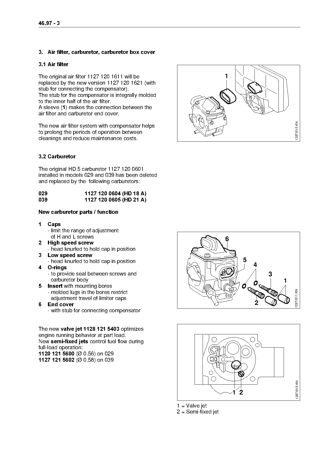
The original air filter 1127 120 1611 will be                            1
replaced by the new version 1127 120 1621 (with
stub for connecting the compensator).
The stub for the compensator is integrally molded
to the inner half of the air filter.
A sleeve E1F=makes the connection between the
air filter and carburetor end cover.

                                                                                                   139TI010 KN
The new air filter system with compensator helps
to prolong the periods of operation between
cleanings and reduce maintenance costs.

3.2=Carburetor

The original HD 5 carburetor 1127 120 0601
installed in models 029 and 039 has been deleted
and replaced by the following carburetors:

029==================1127 120 0604 =HD 18 A
039==================1127 120 0605 =HD 21 A

New carburetor parts / function

1=====Caps
      - limit the range of adjustment
        of H and L screws                                                6
2=====High speed screw
      - head knurled to hold cap in position
3=====Low speed screw
      - head knurled to hold cap in position                                       5
4=====O-rings==========================================================================Q
      - to provide seal between screws and                                                 3
        carburetor body                                                                        1
5=====Insert=with mounting bores
                                                                                                   139TI011 KN
      - molded lugs in the bores restrict
        adjustment travel of limiter caps
6=====End cover========================================================================O
      - with stub for connecting compensator

The new valve jet 1128 121 5403=optimizes
engine running behavior at part load.
New semi-fixed jets=control fuel flow during
full-load operation:
1120 121 5600=EØ 0.56) on 029
1127 121 5602=EØ 0.58) on 039
                                                                                                    139TI015 KN

                                                                             1 2

                                                    1 = Valve jet
                                                    2 = Semi-fixed jet
Page 4 of 8
Text of page 4 — search, copy, screen readers
46.97 - 4

3.2.1=Standard setting

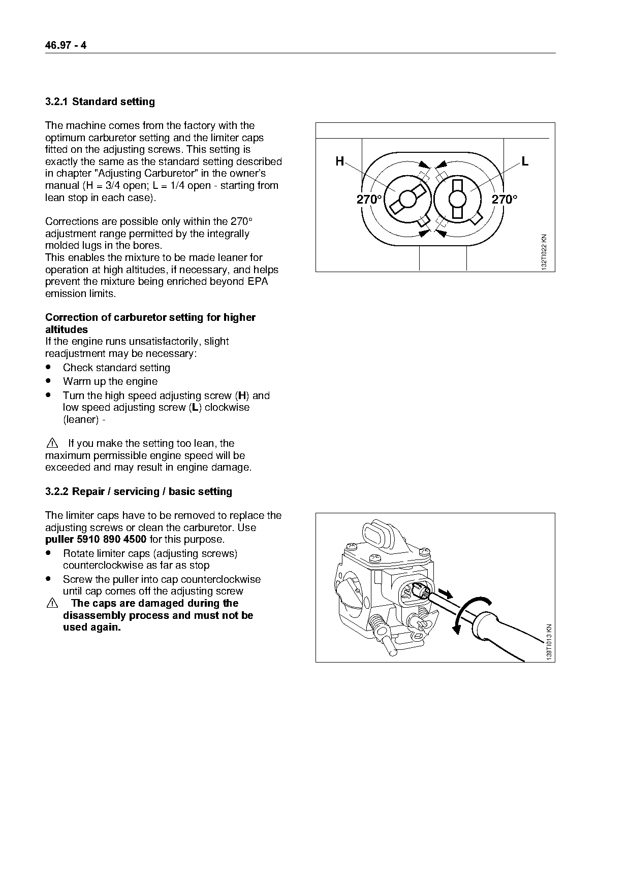
The machine comes from the factory with the
optimum carburetor setting and the limiter caps
fitted on the adjusting screws. This setting is
exactly the same as the standard setting described     H                 L
in chapter "Adjusting Carburetor" in the owner’s
manual (H = 3/4 open; L = 1/4 open - starting from
lean stop in each case).                                   270°   270°
Corrections are possible only within the 270°
adjustment range permitted by the integrally

                                                                             132TI022 KN
molded lugs in the bores.
This enables the mixture to be made leaner for
operation at high altitudes, if necessary, and helps
prevent the mixture being enriched beyond EPA
emission limits.

Correction of carburetor setting for higher
DOWLWXGHV
If the engine runs unsatisfactorily, slight
readjustment may be necessary:
• Check standard setting
• Warm up the engine
• Turn the high speed adjusting screw (+) and
     low speed adjusting screw (/) clockwise
     (leaner) -

! If you make the setting too lean, the
maximum permissible engine speed will be
exceeded and may result in engine damage.

3.2.2=Repair / servicing / basic setting

The limiter caps have to be removed to replace the
adjusting screws or clean the carburetor. Use
puller 5910 890 4500=for this purpose.
• Rotate limiter caps (adjusting screws)
    counterclockwise as far as stop
• Screw the puller into cap counterclockwise
    until cap comes off the adjusting screw
>=The caps are damaged during the
====disassembly process and must not be
    used again.
                                                                                      139TI013 KN
Page 5 of 8
Text of page 5 — search, copy, screen readers
46.97 - 5

Basic setting =without caps

After fitting the adjusting screws, carry out the
basic setting as follows:

• Starting with screws against their seats:
    Open + screw 1 full turn
    Open / screw 1 full turn

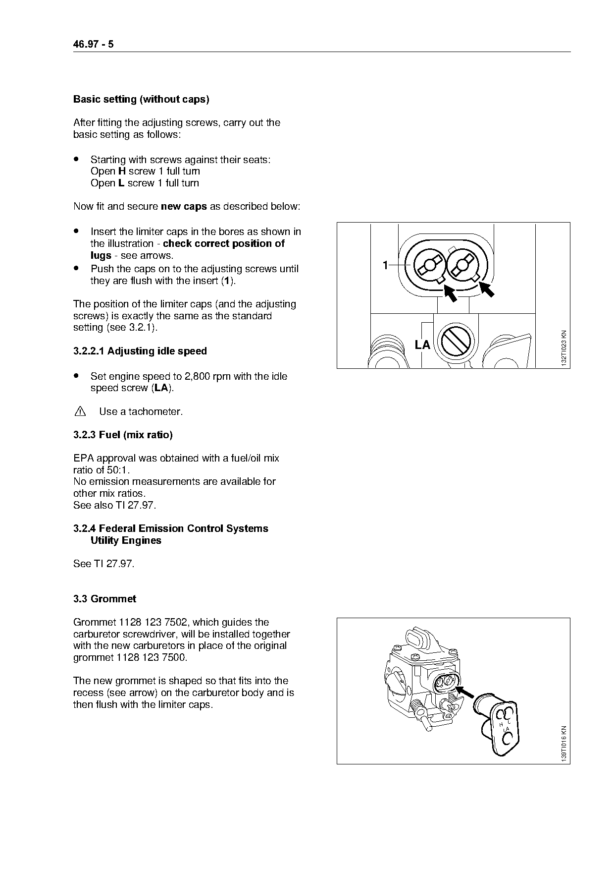
Now fit and secure new caps=~s described below:

• Insert the limiter caps in the bores as shown in
====the=illustr~tion=J=check correct position of
    lugs J=see arrows.
•   Push the caps on to the adjusting screws until    1
    they are flush with the insert E1F.

The position of the limiter caps (and the adjusting
screws) is exactly the same as the standard
setting (see 3.2.1).

                                                                        132TI023 KN
3.2.2.1 Adjusting idle speed
                                                          LA

• Set engine speed to 2,800 rpm with the idle
    speed screw (/$).

!     Use a tachometer.

3.2.3=Fuel =mix ratio

EPA approval was obtained with a fuel/oil mix
ratio of 50:1.
No emission measurements are available for
other mix ratios.
See also TI 27.97.

3.2.4=Federal Emission Control Systems
    Utility Engines

See TI 27.97.

3.3=Grommet

Grommet 1128 123 7502, which guides the
carburetor screwdriver, will be installed together
with the new carburetors in place of the original
grommet 1128 123 7500.

The new grommet is shaped so that fits into the
recess (see arrow) on the carburetor body and is
then flush with the limiter caps.
                                                               H
                                                                        139TI016 KN

                                                                   LA
Page 6 of 8
Text of page 6 — search, copy, screen readers
46.97 - 6

3.4=Carburetor box cover

A carburetor box cover with a modified carburetor
setting symbol (H=3/4, L=1/4) will be installed as
standard.
Replacement carburetor box cover 1127 140 1900
will be supplied without a setting symbol in future
and can therefore be used for both the original and
new versions of the machines.

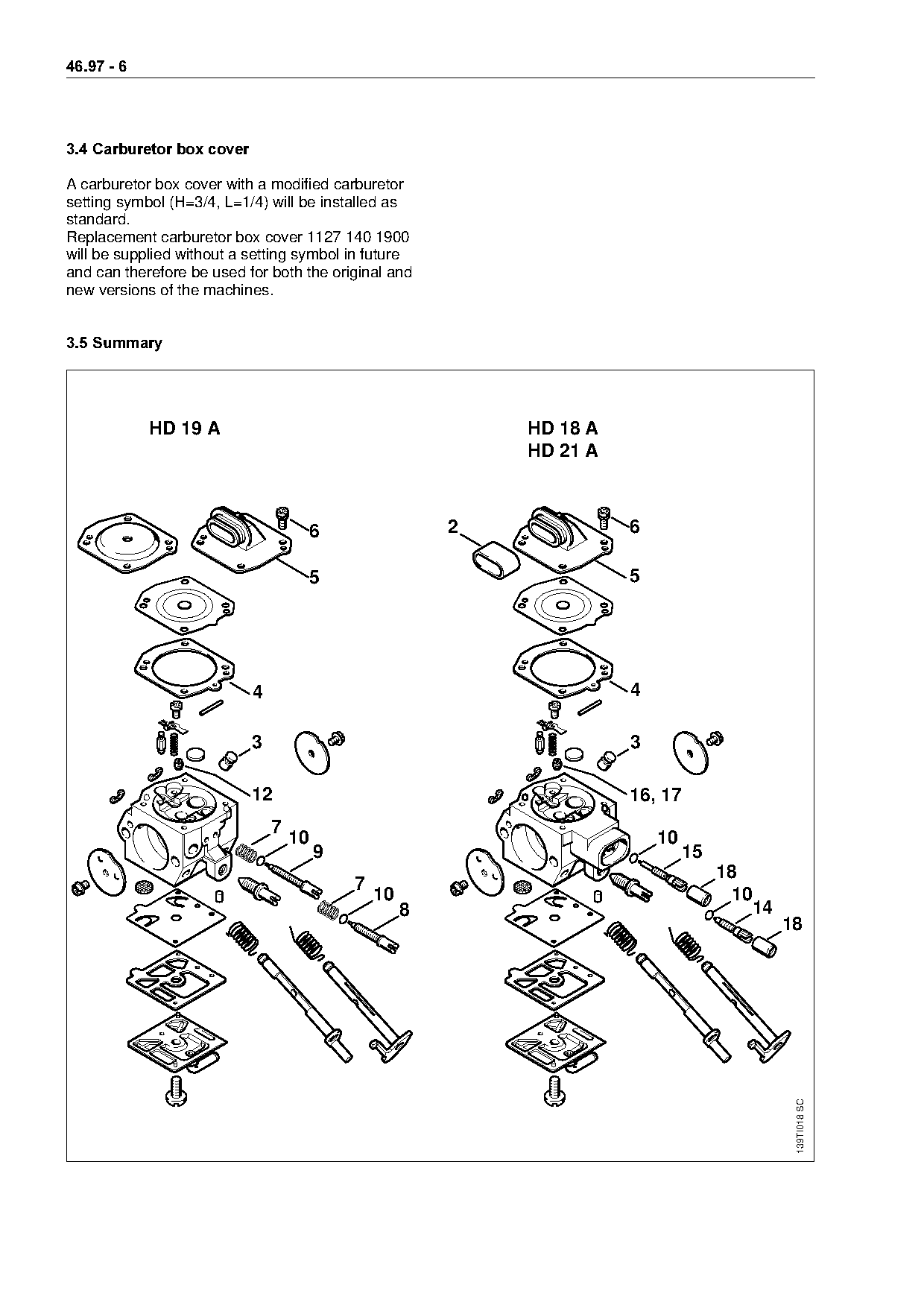
3.5=Summary

            HD 19 A                                          HD 18 A
                                                             HD 21 A

                                        6                2             6

                                        5                              5

                           4                                           4

                           3                                           3

                           12                                          16, 17
                               7
                                   10                                      10
                                        9                                       15
                                                                                     18
                                            7
                                                10                                     10
                                                     8                                   14
                                                                                              18
                                                                                               139TI018 SC
Page 7 of 8
Text of page 7 — search, copy, screen readers
46.97 - 7

Item        Part Name                             Original              New                  Rem.
                                                  version               version

 1          Air filter (fleece)                     1127 120 1611         1127 120 1621          1)
 2          Sleeve                                  ---                   1124 121 9100

            Carburetor HD 5;                        1127 120 0601         ---                    2)
============Carburetor HD 19 AX=====================JJJ===================NNOT=NOM=MSRM==========PF
            each of above includes:
 3          Valve jet                               1115 121 5401         1128 121 5403          1)
 4          Gasket                                  1127 129 0900         1128 129 0906          1)
 5          End cover                               4116 121 0800         1128 121 0801          1)
 6          Round head screw                        1106 122 7400         1121 122 7101          1)
 7          Spring (2x)                             4116 122 3001         1128 122 3003          1)
 8          High speed screw;                       1127 122 6700         1127 122 6701          1)
            including item 10
 9          Low speed screw;                        4116 122 6800         1127 122 6802          1)
            including item 10:
10          Sealing ring                            ---                   -*-                    4)
11          Retaining ring                          1116 122 9000         ---                    1)
12          Fixed jet 58                            1127 121 5600         1127 121 5602          1)
13          Sealing ring                            1120 122 3600         ---                    1)
            All other parts as HD 5 carburetor

============Carburetor HD 18 A =for 029 "EPA"=;=====JJJ===================NNOT=NOM=MSMQ
            including items 3 to 6, 10,
            14 to 16 and 18:
============Carburetor HD 21 A =for 039 "EPA"=;=====JJJ===================NNOT=NOM=MSMR
            including items 3 to 6, 10,
            14, 15, 17 and 18:
14          High speed screw                        ---                   1128 122 6703
            including: item 10
15          Low speed screw                         ---                   1127 122 6801
            including: item 10
16          Fixed jet 56                            ---                   1120 121 5600
17          Fixed jet 58                            ---                   1127 121 5602
18          Cap (2x)                                ---                   4203 121 2700
            All other parts as HD 19 carburetor

            Carburetor parts kit                    1127 007 1060         1127 007 1062          1)
            including: item 4
            All other parts as before

Modification to be introduced: in progress
5HPDUNV
1) Original version of part remains available as spare for older machines
2) Original version of part no longer available from factory
3) New replacement carburetor for all models 029, 039 ZLWKRXW "EPA" approval
   Note:=lriginal end cover 4116 121 0800 comes with replacement HD 19 A carburetor for use on
   machines without compensator
4) Part is not available as separate item
Page 8 of 8
Text of page 8 — search, copy, screen readers
46.97 - 8
4.=Muffler, muffler cover,
===gasket=for thermal insulation
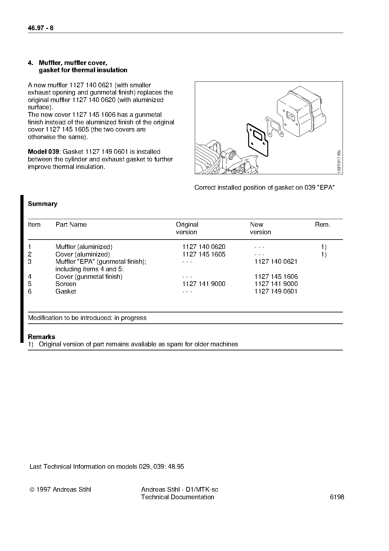
A new muffler 1127 140 0621 (with smaller
exhaust opening and gunmetal finish) replaces the
original muffler 1127 140 0620 (with aluminized
surface).
The new cover 1127 145 1606 has a gunmetal
finish instead of the aluminized finish of the original
cover 1127 145 1605 (the two covers are
otherwise the same).
Model 039W=d~sket 1127 149 0601 is installed
139TI017 KN
between the cylinder and exhaust gasket to further
improve thermal insulation.
Correct installed position of gasket on 039 "EPA"
6XPPDU\
Item Part Name Original New Rem.
version version
1 Muffler (aluminized) 1127 140 0620 --- 1)
2 Cover (aluminized) 1127 145 1605 --- 1)
3 Muffler "EPA" (gunmetal finish); --- 1127 140 0621
including items 4 and 5:
4 Cover (gunmetal finish) --- 1127 145 1606
5 Screen 1127 141 9000 1127 141 9000
6 Gasket --- 1127 149 0601
Modification to be introduced: in progress
5HPDUNV
1) Original version of part remains available as spare for older machines
Last Technical Information on models 029, 039: 48.95
1997 Andreas Stihl Andreas Stihl - D1/MTK-sc
Technical Documentation 6198 Most of these PDFs embed fonts with a shifted character map, so the text above was recovered rather than copied — read it as a faithful but imperfect transcription, and treat the page image above each block as the authority where the two disagree — the figures exist only there, because they are vector drawings that text extraction cannot keep.