Technical Information · issue 47 of 1997
Carburetor; HD filter base; HD filter cover; crank
Model 044, 046 Chainsaws ± Series 1128
IssueTI 47/1997
Engine family 1128
Part changes (3)
| Was | Becomes | What the bulletin says |
|---|---|---|
| 1128 121 5602 | 1128 121 5603 | In addition, the semi-fixed jet E2F=NNOU=NON=RSMO=ETMF=in the HD-16 carburetor for model 046 will be replaced by the new version 1128 121 5603 (68). |
| 0000 400 1303 | 0000 400 1305 | 046:=qhe original ignition module E1F=MMMM=QMM=NPMP=Ewith 3-arm yoke and timing adjustment) will be replaced by the new universal ignition module E2F=MMMM=QMM=NPMR=Ewith 2-arm yoke, without timing adjustment). |
| 0000 400 1300 | 0000 400 1305 | 132TI021 SC 0000 400 1300 will be replaced by the new version MMMM=QMM=NPMR=E2F. |
Full text
Page 1 of 11
Text of page 1 — search, copy, screen readers
Technical Information

                                                                                                47.97

Model 044, 046 Chainsaws ± Series 1128

&RQWHQWV

1. Carburetor (sealed adjusting screws, modified valve jet and semi-fixed jet, new limiter caps)
2. Filter base 044 / grommet (different shape for carburetors with limiter caps, new setting symbols)

3. Filter cover 046 (new setting symbols, neutral replacement filter cover)
4. Engine
   - Ball bearings (cover washers deleted)

   - Crankcase 044 (modified muffler mounting)
   - Muffler (smaller exhaust opening, gasket between casings)
   - 044 heat shield (new - improved heat dissipation)
5. Ignition system
   - 044 flywheel (higher air throughput)
   - Ignition module (new universal ignition module, 046 with 2-arm yoke, without timing adjustment)
6. Front hand guard (new rubber mount)
7. 044 versions available
   - 044 Flush cut handlebar model (0.5 mm cylinder gasket)

   - 044 Arctic with carburetor heating (modified filter configuration)

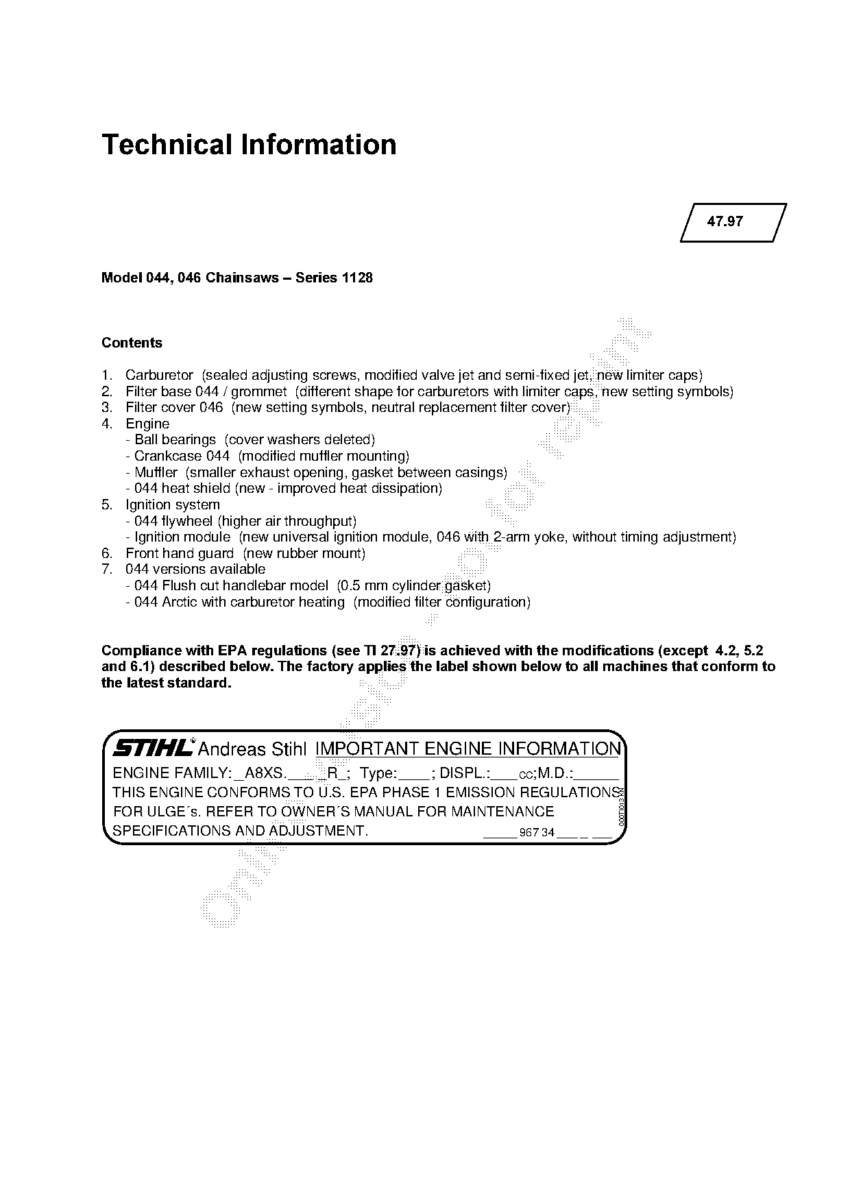
Compliance with EPA regulations =see TI 27.97= is achieved with the modifications =except  4.2, 5.2

and 6.1= described below. The factory applies the label shown below to all machines that conform to

the latest standard.

               Andreas Stihl IMPORTANT ENGINE INFORMATION
 ENGINE FAMILY: A8XS.     R ; Type:    ; DISPL.:   CC;M.D.:

 THIS ENGINE CONFORMS TO U.S. EPA PHASE 1 EMISSION REGULATIONS
                                                                                  000TI013 KN

 FOR ULGE´s. REFER TO OWNER´S MANUAL FOR MAINTENANCE
 SPECIFICATIONS AND ADJUSTMENT.                    967 34
Page 2 of 11
Text of page 2 — search, copy, screen readers
47.97 - 2

1.=Carburetor

The original carburetors will be replaced by the fol-
lowing new versions:

044:=eaJNT=ENNOU=NOM=MSOOF=in place of
     HD-10B (1128 120 0619)
046:=eaJNS=ENNOU=NOM=MSOPF=in place of
     HD-8A (1128 120 0610)

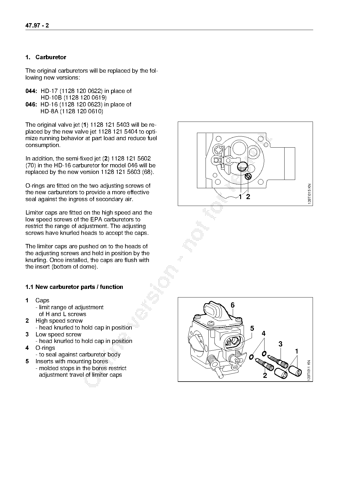
The original valve jet E1F=NNOU=NON=RQMP=will be re-
placed by the new valve jet 1128 121 5404 to opti-
mize running behavior at part load and reduce fuel

consumption.

In addition, the semi-fixed jet E2F=NNOU=NON=RSMO
(70) in the HD-16 carburetor for model 046 will be

replaced by the new version 1128 121 5603 (68).

O-rings are fitted on the two adjusting screws of

                                                                                             139TI015 KN
the new carburetors to provide a more effective
seal against the ingress of secondary air.                            1 2

Limiter caps are fitted on the high speed and the
low speed screws of the EPA carburetors to
restrict the range of adjustment. The adjusting
screws have knurled heads to accept the caps.

The limiter caps are pushed on to the heads of
the adjusting screws and held in position by the
knurling. Once installed, the caps are flush with
the insert (bottom of dome).

1.1=New carburetor parts / function

1===`~ps
    - limit range of adjustment                                   6

      of H and L screws
2===eigh speed screw

    - head knurled to hold cap in position                                  5
3===iow speed screw                                                             4
    - head knurled to hold cap in position
4===lJrings
                                                                                    3

    - to seal against carburetor body
                                                                                        1
5===fnserts with mounting bores
                                                                                            139TI011 KN

    - molded stops in the bores restrict

      adjustment travel of limiter caps                                         2
Page 3 of 11
Text of page 3 — search, copy, screen readers
47.97 - 3

1.2 Service note

The following replacement carburetors should be
used for older machines (without EPA equipment):

044:=eaJNR=ENNOU=NOM=MSORF=in place of
     HD-10B (1128 120 0619)
046:=eaJNQ=ENNOU=NOM=MSOQF=in place of
     HD-8A (1128 120 0610)

With the exception of the limiter caps and adjusting
screws, these carburetors are technically the same
as versions HD-16 and HD-17.

If the limiter caps are removed from
EPA-approved machines in the course of a
repair, new caps have to be fitted after

completing the repair and adjusting the
carburetor as specified.

1.3=Standard setting

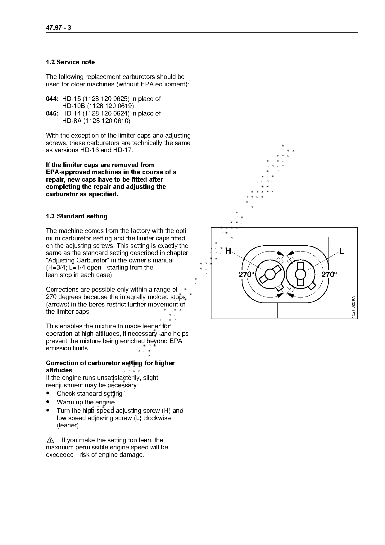
The machine comes from the factory with the opti-
mum carburetor setting and the limiter caps fitted
on the adjusting screws. This setting is exactly the
same as the standard setting described in chapter       H                        L
"Adjusting Carburetor" in the owner’s manual

(H=3/4; L=1/4 open - starting from the
lean stop in each case).                                    270°          270°
Corrections are possible only within a range of

270 degrees because the integrally molded stops

                                                                                     132TI022 KN
(arrows) in the bores restrict further movement of

the limiter caps.

This enables the mixture to made leaner for
operation at high altitudes, if necessary, and helps

prevent the mixture being enriched beyond EPA
emission limits.

Correction of carburetor setting for higher
DOWLWXGHV
If the engine runs unsatisfactorily, slight

readjustment may be necessary:
• Check standard setting
• Warm up the engine

• Turn the high speed adjusting screw (H) and
     low speed adjusting screw (L) clockwise
     (leaner)

>  =ff you make the setting too lean, the
maximum permissible engine speed will be
exceeded - risk of engine damage.
Page 4 of 11
Text of page 4 — search, copy, screen readers
47.97 - 4

1.4=Repair / servicing / basic setting

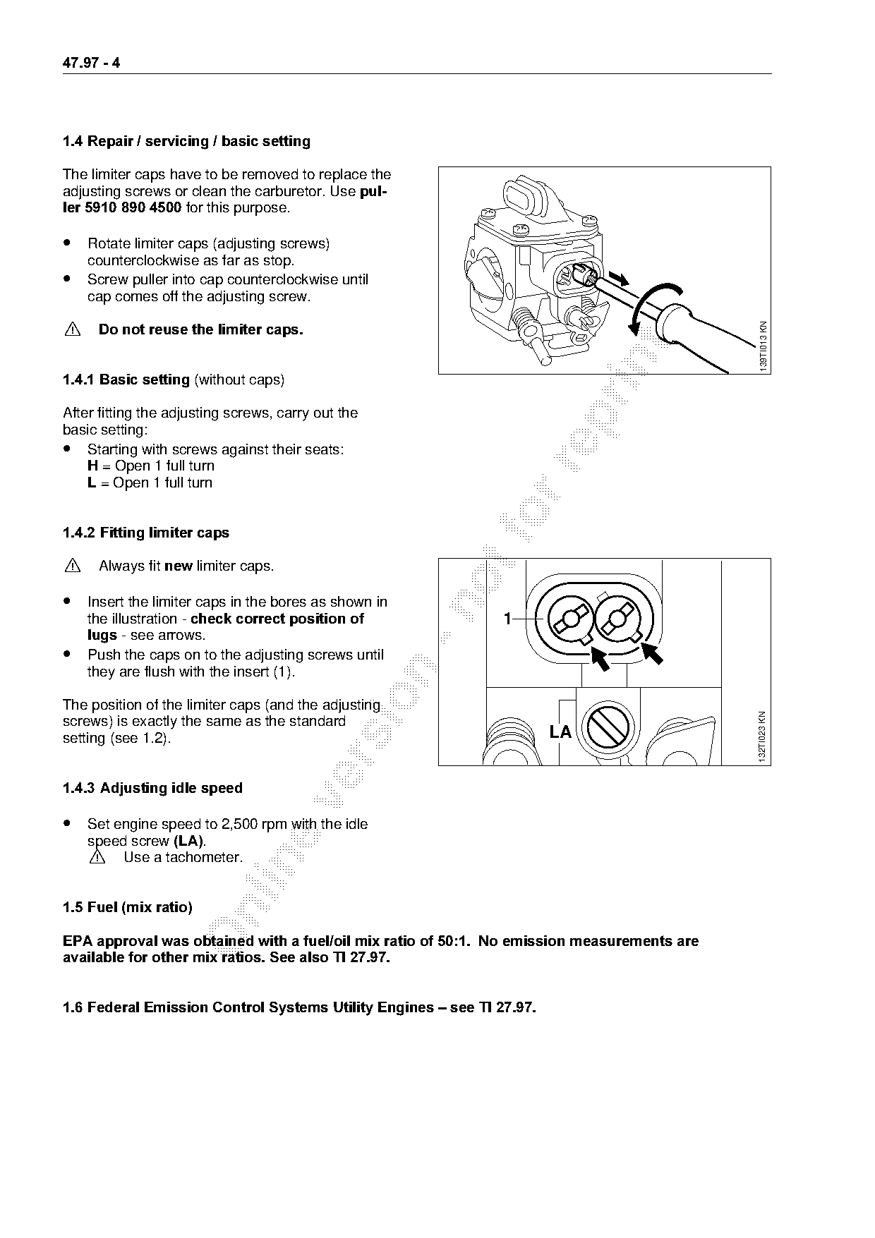
The limiter caps have to be removed to replace the
adjusting screws or clean the carburetor. Use pul-
ler 5910 890 4500=for this purpose.

• Rotate limiter caps (adjusting screws)
    counterclockwise as far as stop.
• Screw puller into cap counterclockwise until
    cap comes off the adjusting screw.

                                                                                               139TI013 KN
>    Do not reuse the limiter caps.

1.4.1 Basic setting Ewithout caps)

After fitting the adjusting screws, carry out the

basic setting:
• Starting with screws against their seats:
    + = Open 1 full turn

    L Z=lpen 1 full turn

1.4.2=Fitting limiter caps
>  =^lw~ys=fit=new=limiter=c~psK

• Insert the limiter caps in the bores as shown in

====the=illustr~tion=J=check correct position of===============N
    OXJV - see arrows.
•   Push the caps on to the adjusting screws until

    they are flush with the insert (1).

The position of the limiter caps (and the adjusting

                                                                                              132TI023 KN
screws) is exactly the same as the standard
setting (see 1.2).                                                     LA

1.4.3=Adjusting idle speed

• Set engine speed to 2,500 rpm with the idle
    speed screw /$ .
    >  =rse a tachometer.

1.5=Fuel =mix ratio

EPA approval was obtained with a fuel/oil mix ratio of 50:1.  No emission measurements are
available for other mix ratios. See also TI 27.97.

1.6=Federal Emission Control Systems Utility Engines ± see TI 27.97.
Page 5 of 11
Text of page 5 — search, copy, screen readers
47.97 - 5

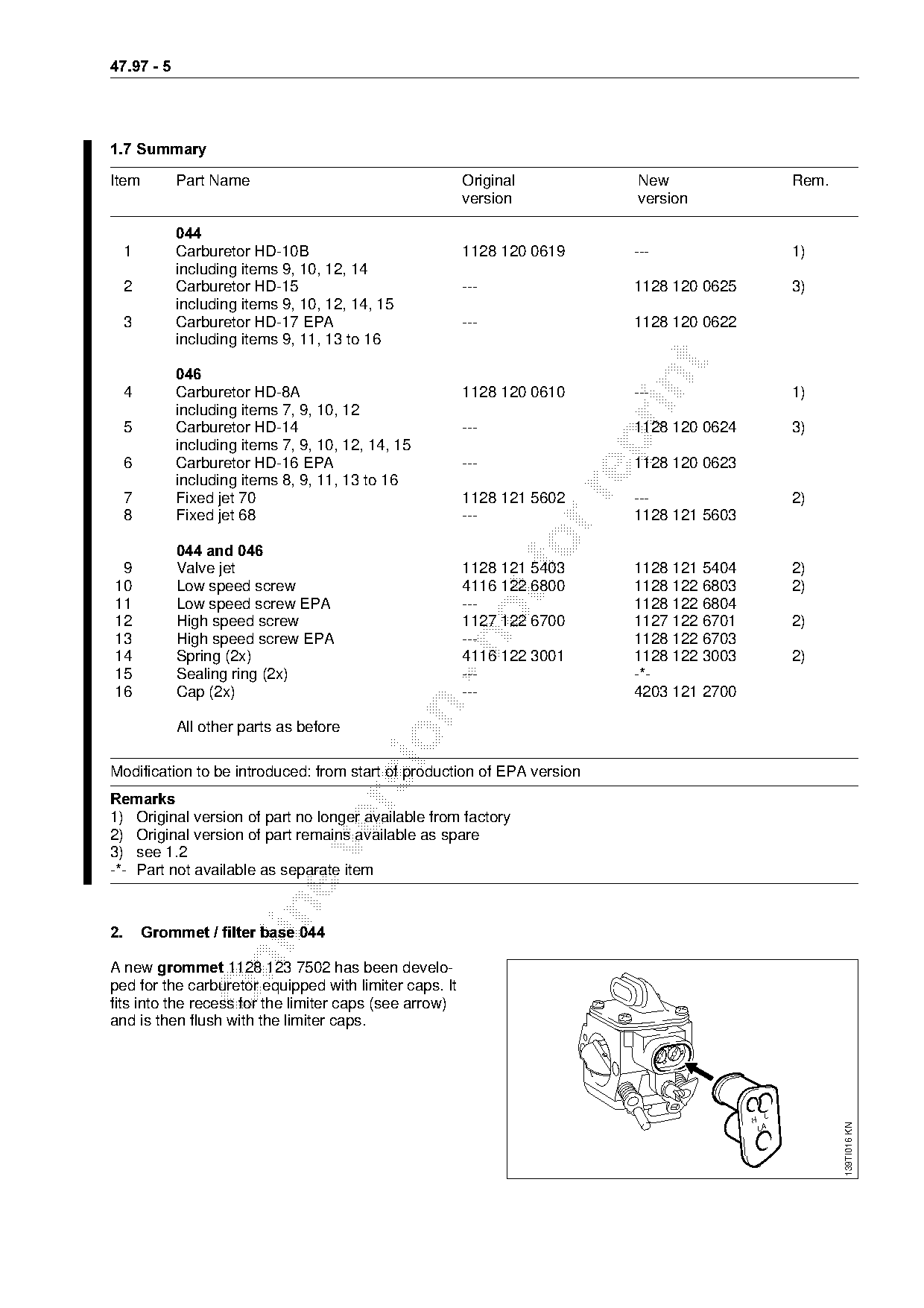
1.7=Summary

Item        Part Name                                   Original         New                      Rem.
                                                        version          version

            044
  1         Carburetor HD-10B                           1128 120 0619    ---                      1)
            including items 9, 10, 12, 14
  2         Carburetor HD-15                            ---              1128 120 0625            3)
            including items 9, 10, 12, 14, 15
  3         Carburetor HD-17 EPA                        ---              1128 120 0622
            including items 9, 11, 13 to 16

            046

  4         Carburetor HD-8A                            1128 120 0610    ---                      1)
            including items 7, 9, 10, 12
  5         Carburetor HD-14                            ---              1128 120 0624            3)

            including items 7, 9, 10, 12, 14, 15
  6         Carburetor HD-16 EPA                        ---              1128 120 0623
            including items 8, 9, 11, 13 to 16

  7         Fixed jet 70                                1128 121 5602    ---                      2)
  8         Fixed jet 68                                ---              1128 121 5603

 9
============044 and 046
            Valve jet
                                                        1128 121 5403    1128 121 5404            2)
10          Low speed screw                             4116 122 6800    1128 122 6803            2)
11          Low speed screw EPA                         ---              1128 122 6804
12          High speed screw                            1127 122 6700    1127 122 6701            2)
13          High speed screw EPA                        ---              1128 122 6703

14          Spring (2x)                                 4116 122 3001    1128 122 3003            2)
15          Sealing ring (2x)                           ---              -*-
16          Cap (2x)                                    ---              4203 121 2700

            All other parts as before

Modification to be introduced: from start of production of EPA version
5HPDUNV

1) Original version of part no longer available from factory
2) Original version of part remains available as spare

3) see 1.2
-*- Part not available as separate item

2.= Grommet / filter base 044

A new JURPPHW 1128 123 7502 has been develo-
ped for the carburetor equipped with limiter caps. It
fits into the recess for the limiter caps (see arrow)
and is then flush with the limiter caps.

                                                                                         H
                                                                                                         139TI016 KN

                                                                                             LA
Page 6 of 11
Text of page 6 — search, copy, screen readers
47.97 - 6

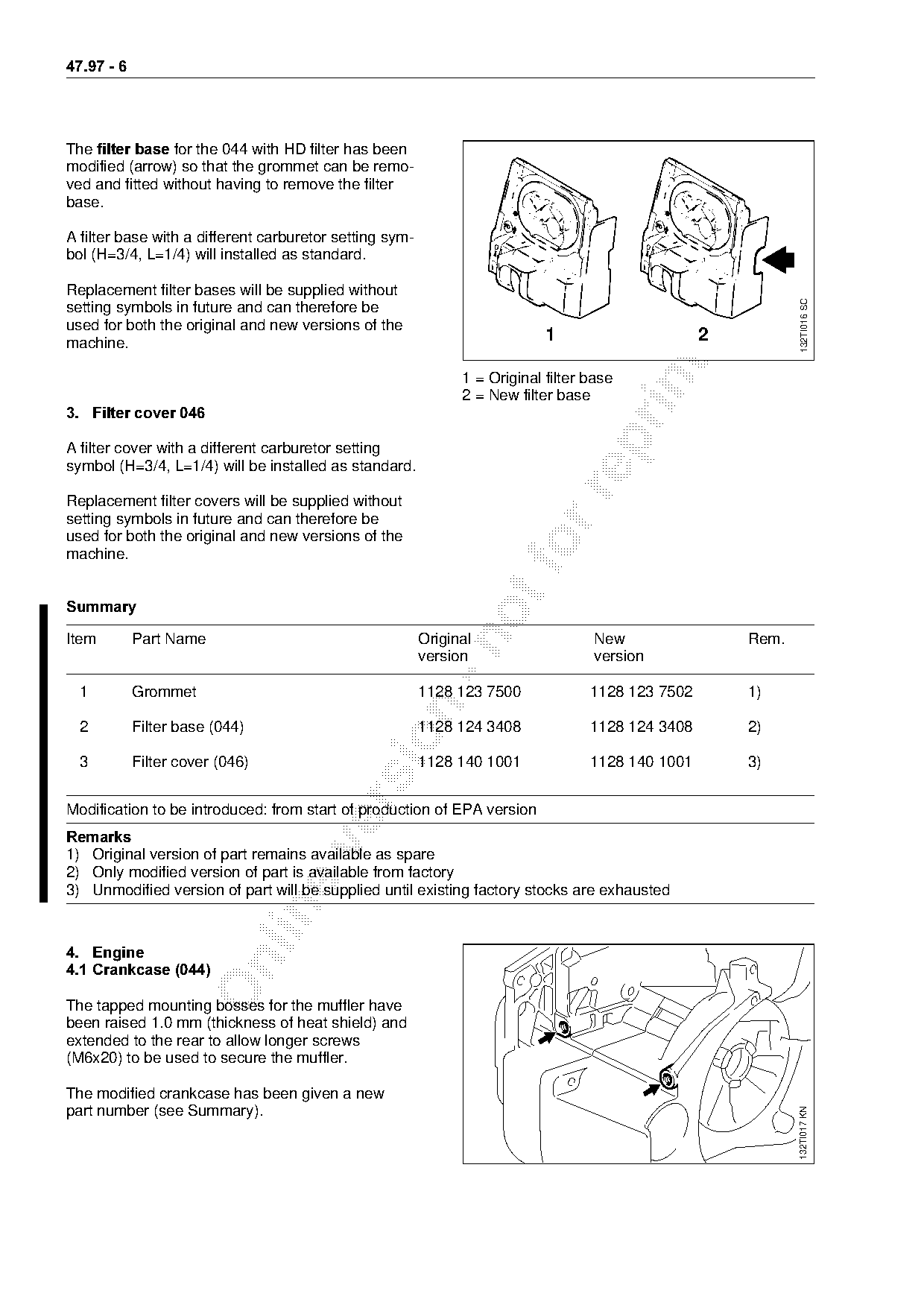
The filter base=for the 044 with HD filter has been
modified (arrow) so that the grommet can be remo-
ved and fitted without having to remove the filter
base.

A filter base with a different carburetor setting sym-
bol (H=3/4, L=1/4) will installed as standard.

Replacement filter bases will be supplied without

                                                                                                               132TI016 SC
setting symbols in future and can therefore be
used for both the original and new versions of the
machine.                                                                    1                      2

                                                               1 = Original filter base

                                                               2 = New filter base
3. =Filter cover 046

A filter cover with a different carburetor setting
symbol (H=3/4, L=1/4) will be installed as standard.

Replacement filter covers will be supplied without
setting symbols in future and can therefore be
used for both the original and new versions of the
machine.                                                               fo
6XPPDU\

Item        Part Name                                    Original                   New                Rem.

                                                         version                    version

  1         Grommet                                      1128 123 7500             1128 123 7502       1)

  2         Filter base (044)                            1128 124 3408             1128 124 3408       2)

  3         Filter cover (046)                           1128 140 1001             1128 140 1001       3)

Modification to be introduced: from start of production of EPA version
5HPDUNV

1) Original version of part remains available as spare
2) Only modified version of part is available from factory
3) Unmodified version of part will be supplied until existing factory stocks are exhausted

4.=Engine

4.1=Crankcase =044

The tapped mounting bosses for the muffler have
been raised 1.0 mm (thickness of heat shield) and
extended to the rear to allow longer screws
(M6x20) to be used to secure the muffler.

The modified crankcase has been given a new
part number (see Summary).
                                                                                                              132TI017 KN
Page 7 of 11
Text of page 7 — search, copy, screen readers
47.97 - 7

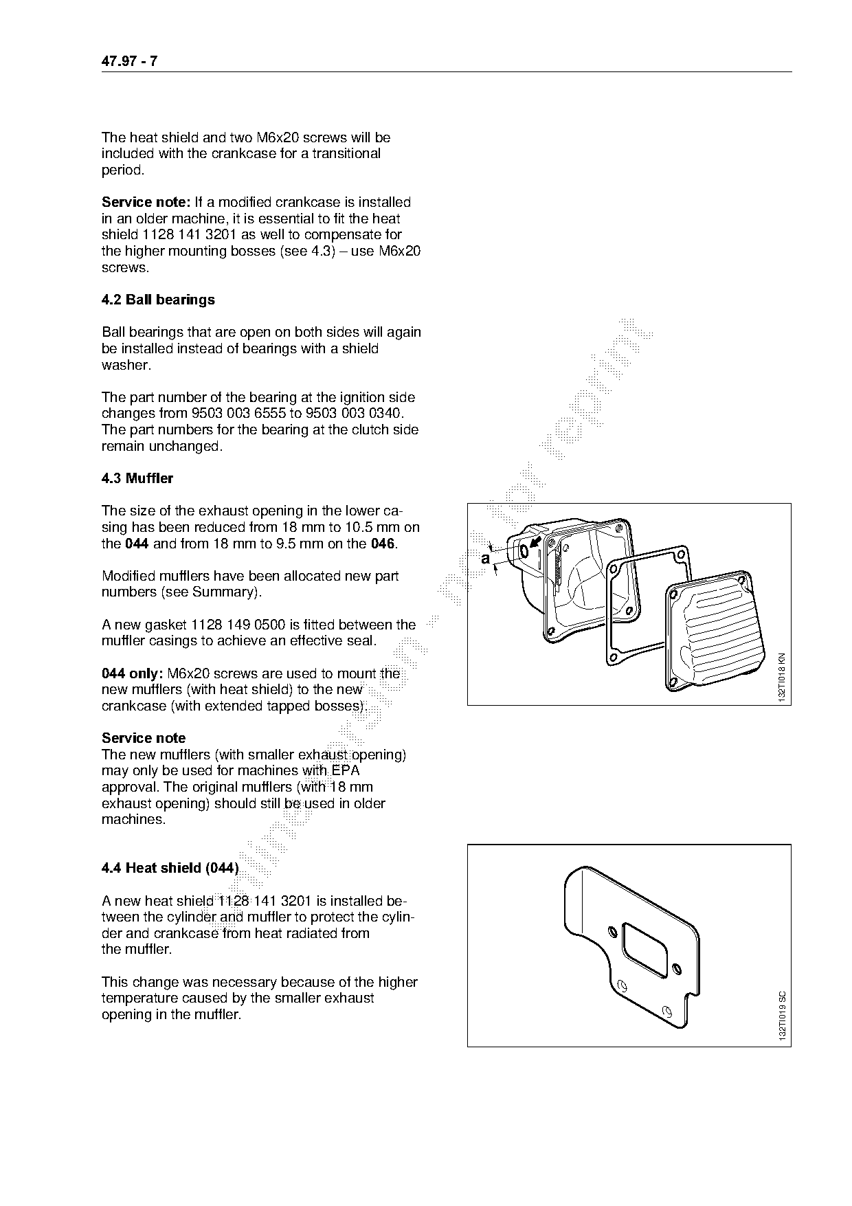
The heat shield and two M6x20 screws will be
included with the crankcase for a transitional
period.

Service note:=ff a modified crankcase is installed
in an older machine, it is essential to fit the heat
shield 1128 141 3201 as well to compensate for
the higher mounting bosses (see 4.3) – use M6x20
screws.

4.2=Ball bearings

Ball bearings that are open on both sides will again

be installed instead of bearings with a shield

washer.

The part number of the bearing at the ignition side

changes from 9503 003 6555 to 9503 003 0340.
The part numbers for the bearing at the clutch side
remain unchanged.

4.3=Muffler

The size of the exhaust opening in the lower ca-
sing has been reduced from 18 mm to 10.5 mm on
the 044=~nd from 18 mm to 9.5 mm on the 046.
                                                        a
Modified mufflers have been allocated new part

numbers (see Summary).

A new gasket 1128 149 0500 is fitted between the
muffler casings to achieve an effective seal.

                                                                     132TI018 KN
044 only:=jSx20 screws are used to mount the

new mufflers (with heat shield) to the new
crankcase (with extended tapped bosses).

Service note

The new mufflers (with smaller exhaust opening)
may only be used for machines with EPA

approval. The original mufflers (with 18 mm
exhaust opening) should still be used in older
machines.

4.4=Heat shield =044

A new heat shield 1128 141 3201 is installed be-
tween the cylinder and muffler to protect the cylin-
der and crankcase from heat radiated from
the muffler.

This change was necessary because of the higher
                                                                     132TI019 SC

temperature caused by the smaller exhaust
opening in the muffler.
Page 8 of 11
Text of page 8 — search, copy, screen readers
47.97 - 8

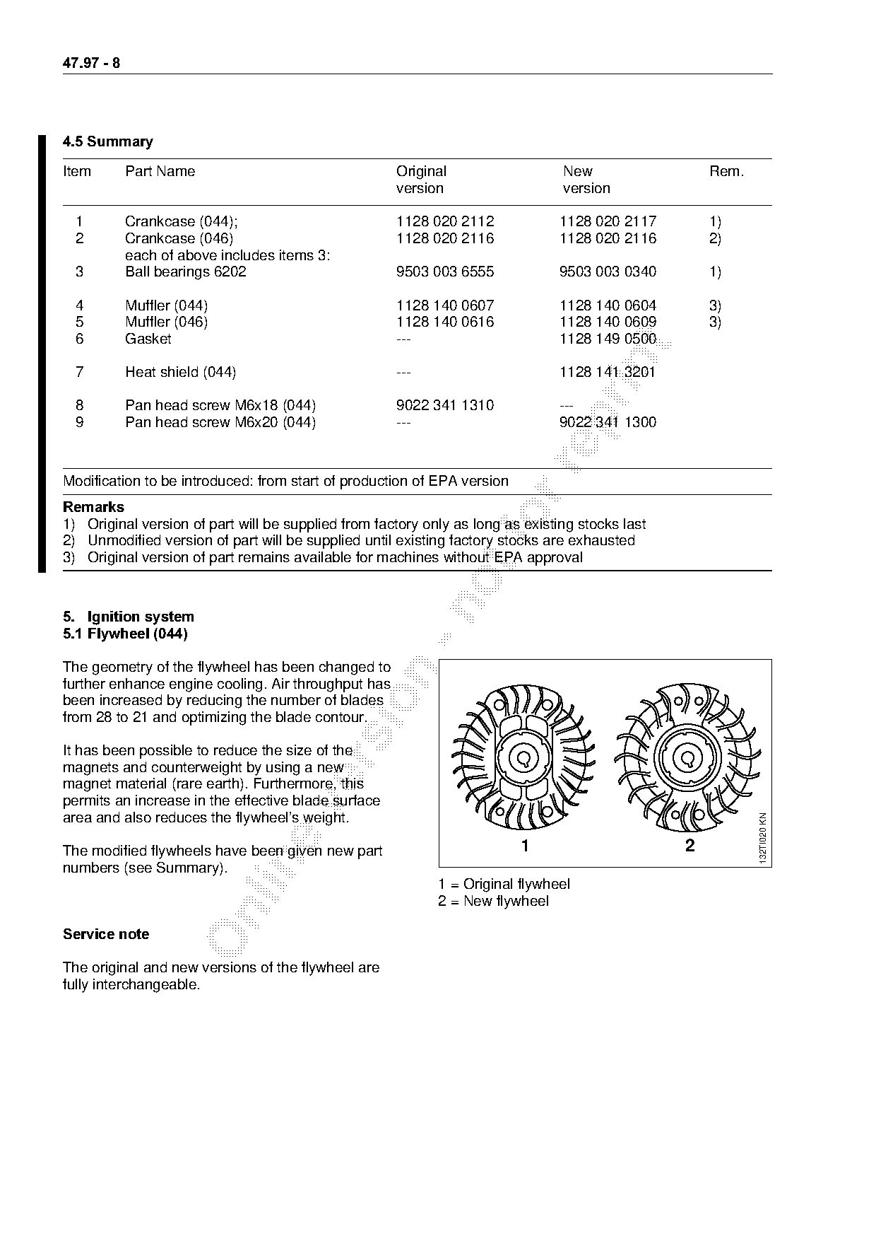
4.5 Summary

Item        Part Name                                Original                   New                  Rem.
                                                     version                    version

  1         Crankcase (044);                         1128 020 2112              1128 020 2117        1)
  2         Crankcase (046)                          1128 020 2116              1128 020 2116        2)
            each of above includes items 3:
  3         Ball bearings 6202                       9503 003 6555              9503 003 0340        1)

  4         Muffler (044)                            1128 140 0607              1128 140 0604        3)
  5         Muffler (046)                            1128 140 0616              1128 140 0609        3)
  6         Gasket                                   ---                        1128 149 0500

  7         Heat shield (044)                        ---                        1128 141 3201

  8         Pan head screw M6x18 (044)               9022 341 1310              ---

  9         Pan head screw M6x20 (044)               ---                        9022 341 1300

Modification to be introduced: from start of production of EPA version
5HPDUNV
1) Original version of part will be supplied from factory only as long as existing stocks last
2) Unmodified version of part will be supplied until existing factory stocks are exhausted
3) Original version of part remains available for machines without EPA approval

5.=Ignition system
5.1=Flywheel =044

The geometry of the flywheel has been changed to

further enhance engine cooling. Air throughput has

been increased by reducing the number of blades
from 28 to 21 and optimizing the blade contour.

It has been possible to reduce the size of the

magnets and counterweight by using a new
magnet material (rare earth). Furthermore, this
permits an increase in the effective blade surface

area and also reduces the flywheel’s weight.
                                                                                                            132TI020 KN

The modified flywheels have been given new part                          1                       2

numbers (see Summary).
                                                            1 = Original flywheel
                                                            2 = New flywheel

Service note

The original and new versions of the flywheel are
fully interchangeable.
Page 9 of 11
Text of page 9 — search, copy, screen readers
47.97 -

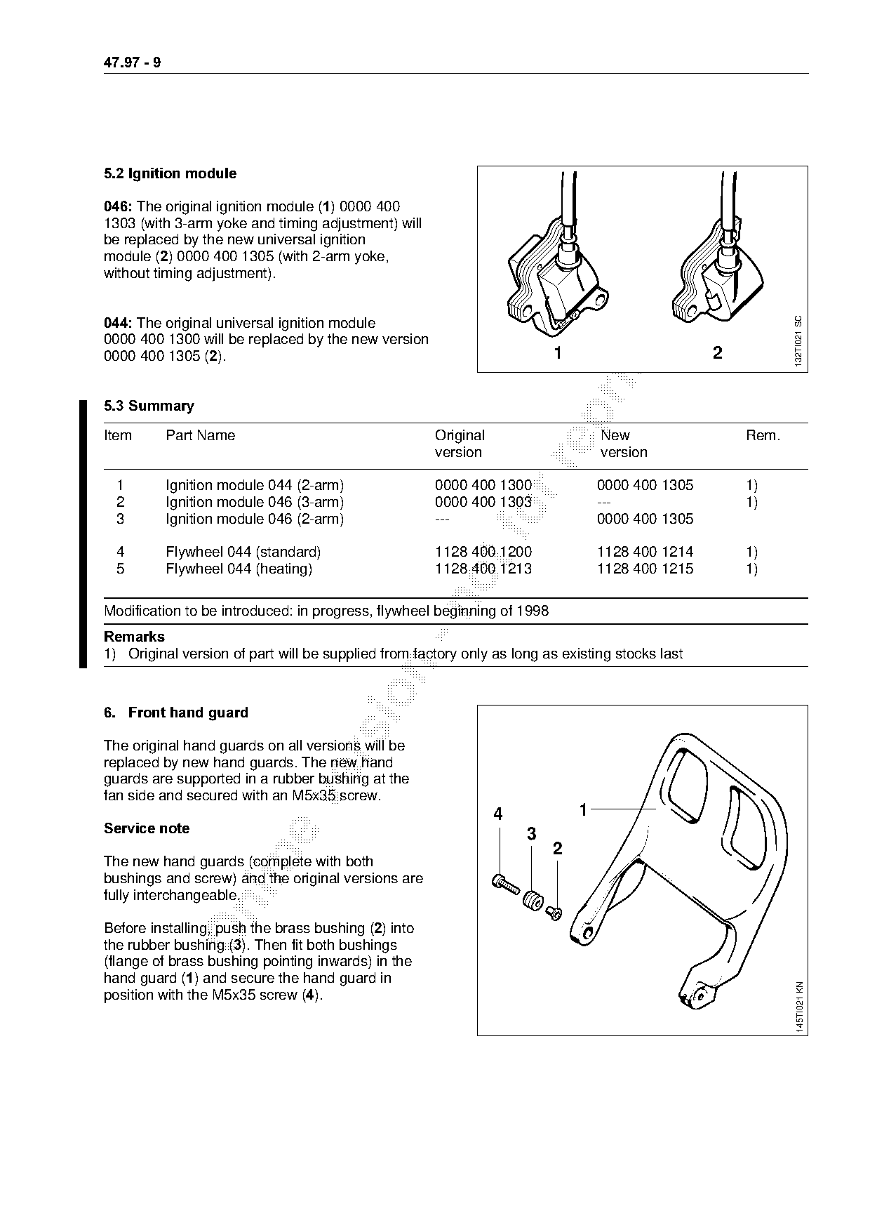
5.2=Ignition module

046:=qhe original ignition module E1F=MMMM=QMM
1303 (with 3-arm yoke and timing adjustment) will
be replaced by the new universal ignition
module E2F=MMMM=QMM=NPMR=Ewith 2-arm yoke,
without timing adjustment).

044:=qhe original universal ignition module

                                                                                                            132TI021 SC
0000 400 1300 will be replaced by the new version

MMMM=QMM=NPMR=E2FK=======================================================N=======================O

5.3=Summary

Item        Part Name                                Original                    New                 Rem.
                                                     version                     version

  1         Ignition module 044 (2-arm)              0000 400 1300               0000 400 1305       1)
  2         Ignition module 046 (3-arm)              0000 400 1303               ---                 1)
  3         Ignition module 046 (2-arm)              ---     fo                  0000 400 1305

  4         Flywheel 044 (standard)                  1128 400 1200               1128 400 1214       1)
  5         Flywheel 044 (heating)                   1128 400 1213               1128 400 1215       1)

Modification to be introduced: in progress, flywheel beginning of 1998
5HPDUNV
1) Original version of part will be supplied from factory only as long as existing stocks last

6.=Front hand guard

The original hand guards on all versions will be

replaced by new hand guards. The new hand
guards are supported in a rubber bushing at the
fan side and secured with an M5x35 screw.

                                                                4            1
Service note========================================================P
                                                                         2

The new hand guards (complete with both
bushings and screw) and the original versions are
fully interchangeable.

Before installing, push the brass bushing E2F=into
the rubber bushing E3FK=qhen fit both bushings
(flange of brass bushing pointing inwards) in the
hand guard E1F=~nd secure the hand guard in
                                                                                                              145TI021 KN

position with the M5x35 screw E4F.
Page 10 of 11
Text of page 10 — search, copy, screen readers
47.97 - 10

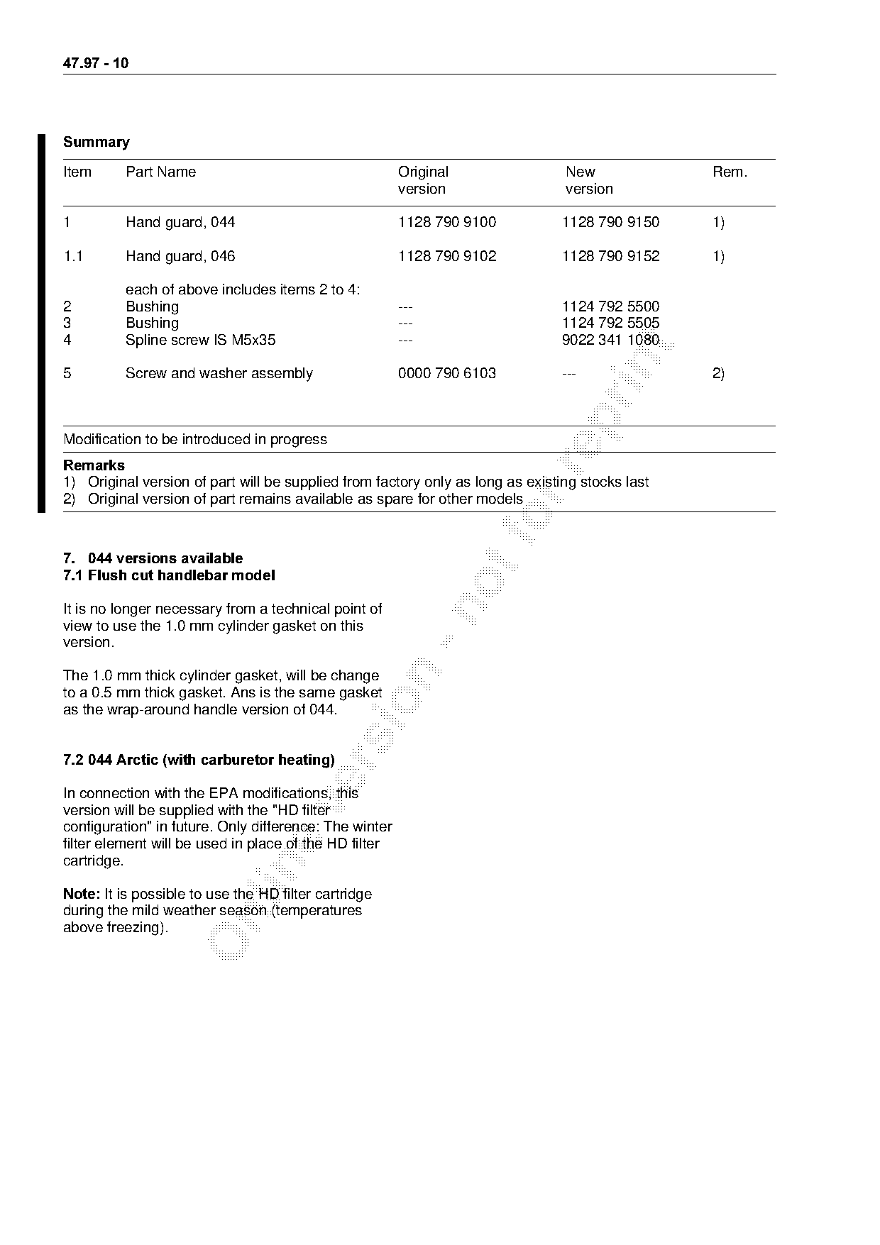
6XPPDU\

Item      Part Name                                     Original                New              Rem.
                                                        version                 version

1         Hand guard, 044                               1128 790 9100           1128 790 9150    1)

1.1       Hand guard, 046                               1128 790 9102           1128 790 9152    1)

          each of above includes items 2 to 4:
2         Bushing                                       ---                     1124 792 5500
3         Bushing                                       ---                     1124 792 5505
4         Spline screw IS M5x35                         ---                     9022 341 1080

5         Screw and washer assembly                     0000 790 6103           ---              2)

Modification to be introduced in progress
5HPDUNV

1) Original version of part will be supplied from factory only as long as existing stocks last
2) Original version of part remains available as spare for other models
7.=044 versions available
7.1=Flush cut handlebar model

It is no longer necessary from a technical point of

view to use the 1.0 mm cylinder gasket on this
version.

The 1.0 mm thick cylinder gasket, will be change
to a 0.5 mm thick gasket. Ans is the same gasket

as the wrap-around handle version of 044.

7.2=044 Arctic =with carburetor heating

In connection with the EPA modifications, this

version will be supplied with the "HD filter
configuration" in future. Only difference: The winter
filter element will be used in place of the HD filter
cartridge.

Note: ft is possible to use the HD filter cartridge
during the mild weather season (temperatures

above freezing).
Page 11 of 11
Text of page 11 — search, copy, screen readers
47.97 - 11
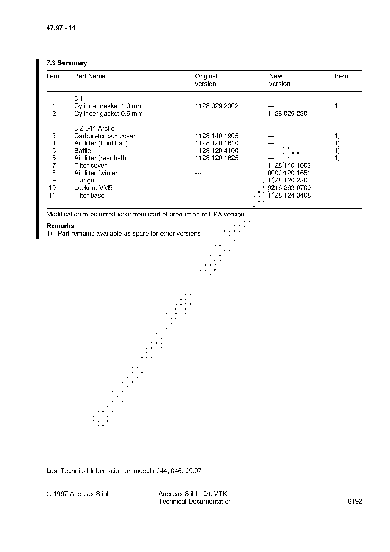
7.3=Summary
Item Part Name Original New Rem.
version version
6.1
1 Cylinder gasket 1.0 mm 1128 029 2302 --- 1)
2 Cylinder gasket 0.5 mm --- 1128 029 2301
6.2 044 Arctic
3 Carburetor box cover 1128 140 1905 --- 1)
4 Air filter (front half) 1128 120 1610 --- 1)
5 Baffle 1128 120 4100 --- 1)
6 Air filter (rear half) 1128 120 1625 --- 1)
7 Filter cover --- 1128 140 1003
8 Air filter (winter) --- 0000 120 1651
9 Flange --- 1128 120 2201
10 Locknut VM5 --- 9216 263 0700
11 Filter base --- 1128 124 3408
Modification to be introduced: from start of production of EPA version
5HPDUNV
1) Part remains available as spare for other versions fo
Last Technical Information on models 044, 046: 09.97
1997 Andreas Stihl Andreas Stihl - D1/MTK
Technical Documentation 6192 Most of these PDFs embed fonts with a shifted character map, so the text above was recovered rather than copied — read it as a faithful but imperfect transcription, and treat the page image above each block as the authority where the two disagree — the figures exist only there, because they are vector drawings that text extraction cannot keep.