Technical Information · issue 51 of 1997
Carburetor (fixed-jet); fan housing
Model 019 T Chainsaws - Series 1132
Part changes (1)
| Was | Becomes | What the bulletin says |
|---|---|---|
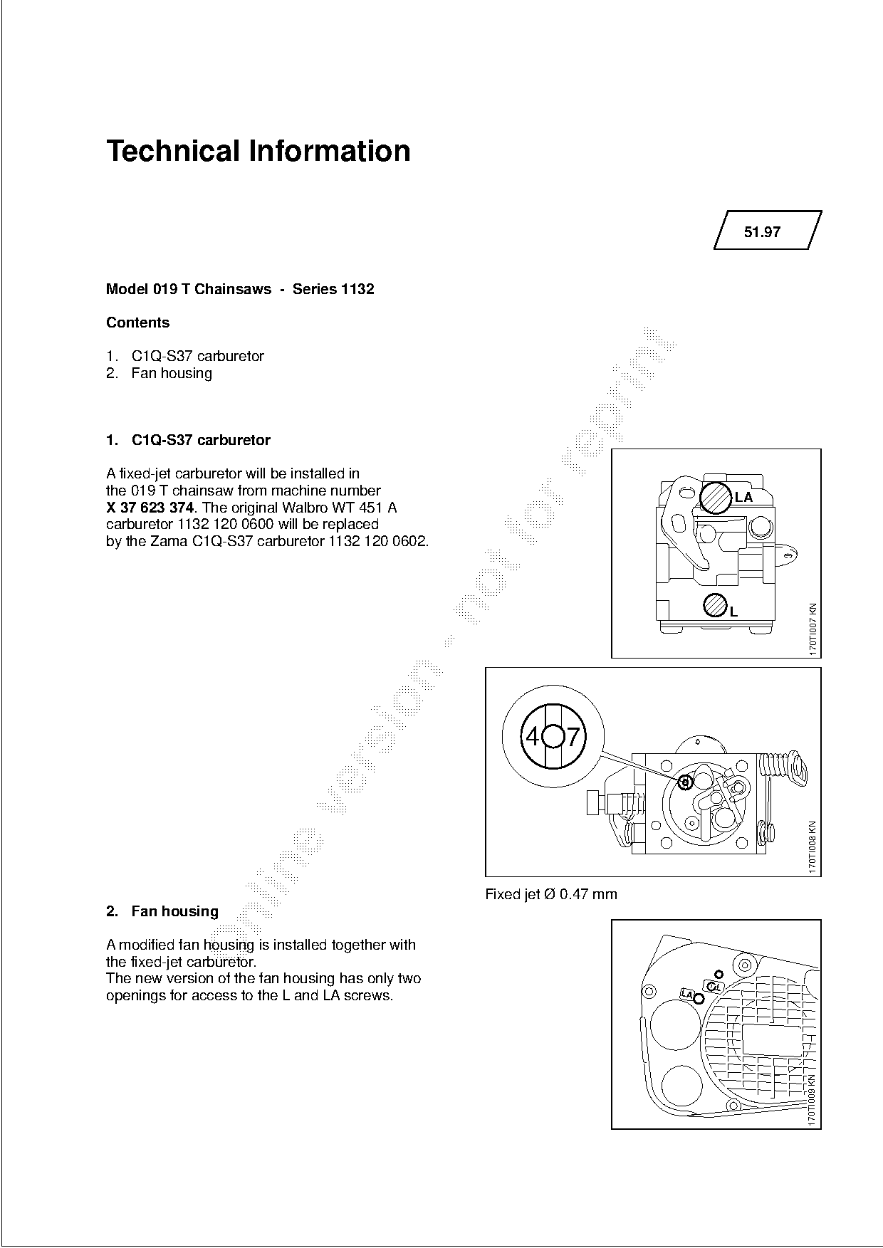
| 1132 120 0600 | 1132 120 0602 | The original Walbro WT 451 A carburetor 1132 120 0600 will be replaced by the Zama C1Q-S37 carburetor 1132 120 0602. |
Full text
Page 1 of 2
Text of page 1 — search, copy, screen readers
Technical Information

                                                                                         51.97

Model 019 T Chainsaws - Series 1132

Contents

1. C1Q-S37 carburetor

2. Fan housing

1. C1Q-S37 carburetor

A fixed-jet carburetor will be installed in
the 019 T chainsaw from machine number                                               LA
X 37 623 374. The original Walbro WT 451 A
carburetor 1132 120 0600 will be replaced
by the Zama C1Q-S37 carburetor 1132 120 0602.

                                                                                                  170TI007 KN

                                                         4 7

                                                                                                  170TI008 KN

                                                    Fixed jet Ø 0.47 mm
2. Fan housing

A modified fan housing is installed together with
the fixed-jet carburetor.
The new version of the fan housing has only two                                1 L
openings for access to the L and LA screws.                               LA
                                                                                                 170TI009 KN
Page 2 of 2
Text of page 2 — search, copy, screen readers
51.97 - 2
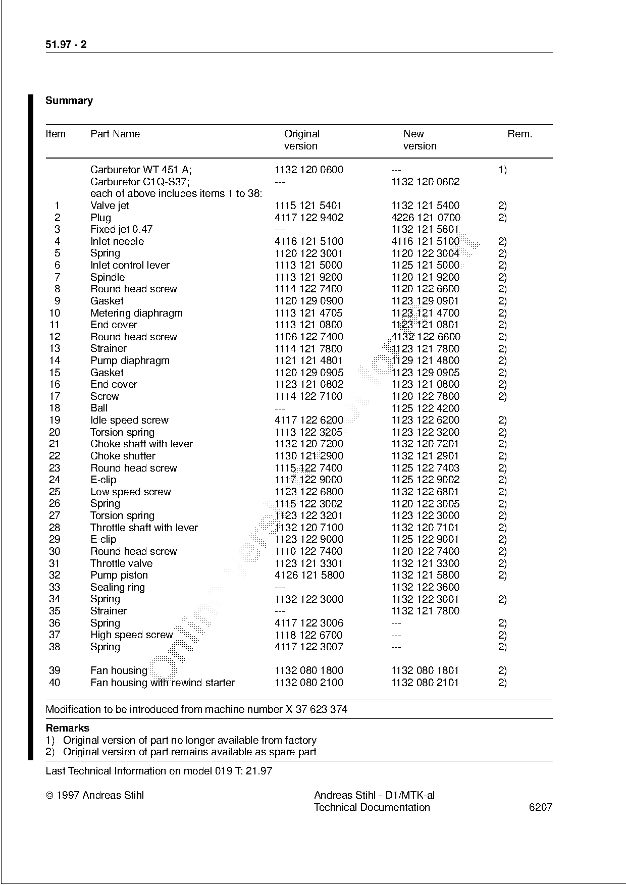
Summary
Item Part Name Original New Rem.
version version
Carburetor WT 451 A; 1132 120 0600 --- 1)
Carburetor C1Q-S37; --- 1132 120 0602
each of above includes items 1 to 38:
1 Valve jet 1115 121 5401 1132 121 5400 2)
2 Plug 4117 122 9402 4226 121 0700 2)
3 Fixed jet 0.47 --- 1132 121 5601
4 Inlet needle 4116 121 5100 4116 121 5100 2)
5 Spring 1120 122 3001 1120 122 3004 2)
6 Inlet control lever 1113 121 5000 1125 121 5000 2)
7 Spindle 1113 121 9200 1120 121 9200 2)
8 Round head screw 1114 122 7400 1120 122 6600 2)
9 Gasket 1120 129 0900 1123 129 0901 2)
10 Metering diaphragm 1113 121 4705 1123 121 4700 2)
11 End cover 1113 121 0800 1123 121 0801 2)
12 Round head screw 1106 122 7400 4132 122 6600 2)
13 Strainer 1114 121 7800 1123 121 7800 2)
14 Pump diaphragm 1121 121 4801 1129 121 4800 2)
15
16
Gasket
End cover
1120 129 0905
1123 121 0802
fo 1123 129 0905
1123 121 0800
2)
2)
17 Screw 1114 122 7100 1120 122 7800 2)
18 Ball --- 1125 122 4200
19 Idle speed screw 4117 122 6200 1123 122 6200 2)
20 Torsion spring 1113 122 3205
1123 122 3200 2)
21 Choke shaft with lever 1132 120 7200 1132 120 7201 2)
22 Choke shutter 1130 121 2900 1132 121 2901 2)
23 Round head screw 1115 122 7400 1125 122 7403 2)
24 E-clip 1117 122 9000 1125 122 9002 2)
25 Low speed screw 1123 122 6800 1132 122 6801 2)
26 Spring 1115 122 3002 1120 122 3005 2)
27 Torsion spring 1123 122 3201 1123 122 3000 2)
28 Throttle shaft with lever 1132 120 7100 1132 120 7101 2)
29 E-clip 1123 122 9000 1125 122 9001 2)
30 Round head screw 1110 122 7400 1120 122 7400 2)
31 Throttle valve 1123 121 3301 1132 121 3300 2)
32 Pump piston 4126 121 5800 1132 121 5800 2)
33 Sealing ring --- 1132 122 3600
34 Spring 1132 122 3000 1132 122 3001 2)
35 Strainer --- 1132 121 7800
36 Spring 4117 122 3006 --- 2)
37 High speed screw 1118 122 6700 --- 2)
38 Spring 4117 122 3007 --- 2)
39 Fan housing 1132 080 1800 1132 080 1801 2)
40 Fan housing with rewind starter 1132 080 2100 1132 080 2101 2)
Modification to be introduced from machine number X 37 623 374
Remarks
1) Original version of part no longer available from factory
2) Original version of part remains available as spare part
Last Technical Information on model 019 T: 21.97
1997 Andreas Stihl Andreas Stihl - D1/MTK-al
Technical Documentation 6207 Most of these PDFs embed fonts with a shifted character map, so the text above was recovered rather than copied — read it as a faithful but imperfect transcription, and treat the page image above each block as the authority where the two disagree — the figures exist only there, because they are vector drawings that text extraction cannot keep.