Technical Information · issue 2 of 1998
066: Carburetor; grommet; cylinder with piston; fi
Model 066 Chainsaws - Series 1122
IssueTI 2/1998
Engine family 1122
Part changes (1)
| Was | Becomes | What the bulletin says |
|---|---|---|
| 1122 120 0616 | 1122 120 0618 | The original WJ-65 carburetor 1122 120 0616 will be replaced by the WJ-69 carburetor 1122 120 0618. |
Full text
Page 1 of 6
Text of page 1 — search, copy, screen readers
Technical Information

                                                                                                   02.98

Model 066 Chainsaws - Series 1122

Contents

1.    Carburetor

2.    Grommet
3.    Cylinder with piston
4.    Filter cover

5.    Muffler/gasket

Compliance with EPA regulations (see TI 27.97) is achieved with the modifications described
below. The factory applies the label shown below to all machines that conform to the
latest standard.
                     Andreas Stihl IMPORTANT ENGINE INFORMATION
       ENGINE FAMILY: A8XS.     R ; Type:    ; DISPL.:   CC;M.D.:
       THIS ENGINE CONFORMS TO U.S. EPA PHASE 1 EMISSION REGULATIONS

                                                                                 000TI013 KN

       FOR ULGE´s. REFER TO OWNER´S MANUAL FOR MAINTENANCE
       SPECIFICATIONS AND ADJUSTMENT.                    967 34

1.      Carburetor

The original WJ-65 carburetor 1122 120 0616
will be replaced by the WJ-69 carburetor
1122 120 0618. Limiter caps are fitted on the high

speed and the low speed screws of the new carbu-
retor to restrict the range of adjustment.

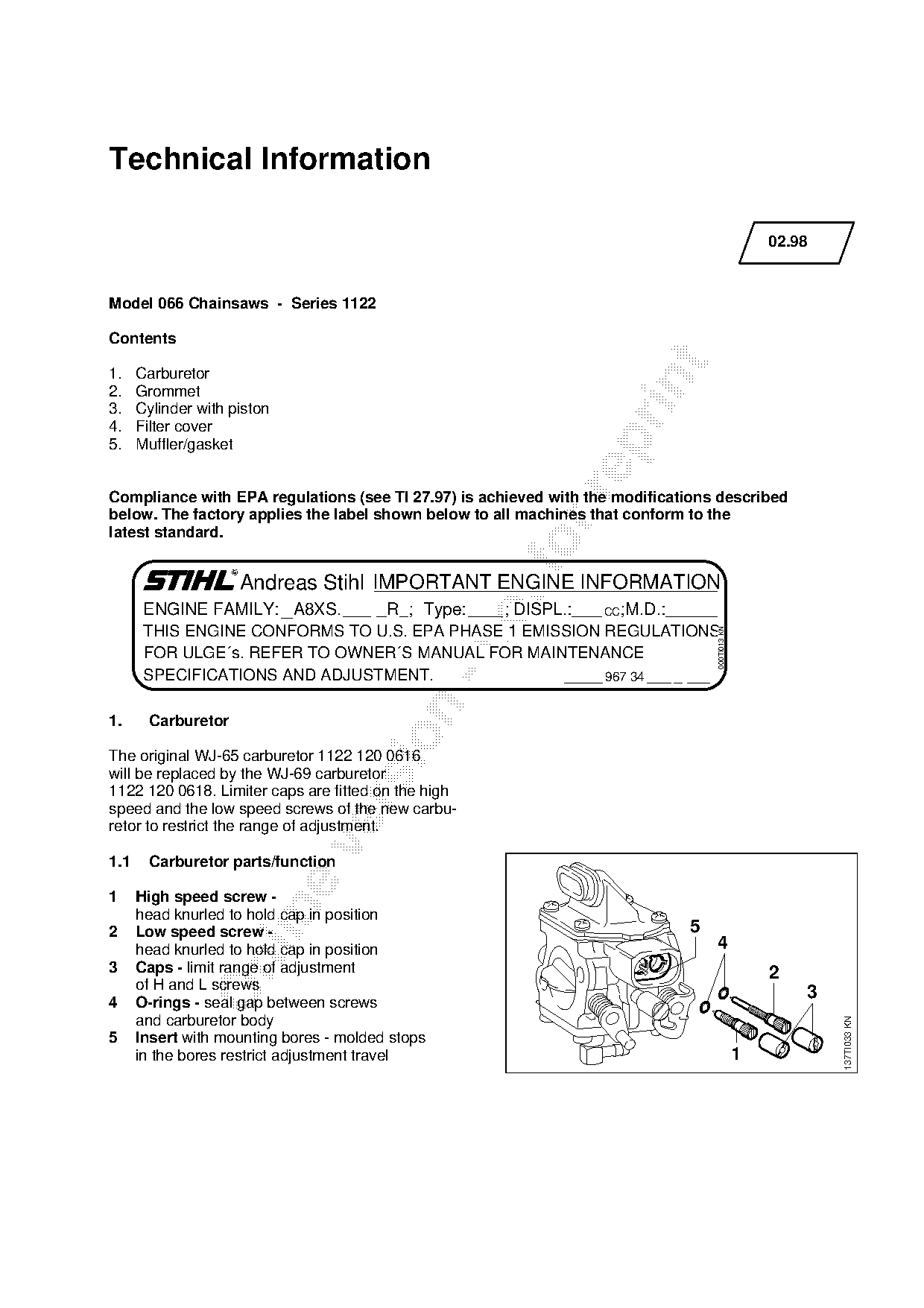
1.1     Carburetor parts/function

1     High speed screw -

      head knurled to hold cap in position
2     Low speed screw -                                                      5
      head knurled to hold cap in position                                       4

3     Caps - limit range of adjustment                                                             2
      of H and L screws
                                                                                                       3
4     O-rings - seal gap between screws
      and carburetor body
                                                                                                           137TI033 KN

5     Insert with mounting bores - molded stops
      in the bores restrict adjustment travel                                                  1
Page 2 of 6
Text of page 2 — search, copy, screen readers
02.98 - 2

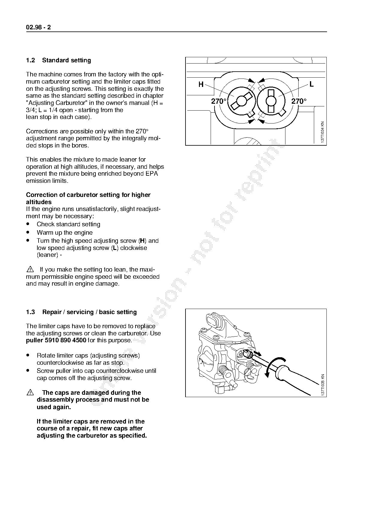
1.2    Standard setting

The machine comes from the factory with the opti-
mum carburetor setting and the limiter caps fitted                                    L
                                                            H
on the adjusting screws. This setting is exactly the
same as the standard setting described in chapter
"Adjusting Carburetor" in the owner’s manual (H =               270°           270°
3/4; L = 1/4 open - starting from the
lean stop in each case).

                                                                                          137TI034 KN
Corrections are possible only within the 270°
adjustment range permitted by the integrally mol-
ded stops in the bores.

This enables the mixture to made leaner for
operation at high altitudes, if necessary, and helps
prevent the mixture being enriched beyond EPA

emission limits.

Correction of carburetor setting for higher

altitudes
If the engine runs unsatisfactorily, slight readjust-
ment may be necessary:
• Check standard setting
• Warm up the engine
• Turn the high speed adjusting screw (H) and
     low speed adjusting screw (L) clockwise
     (leaner) -

>   If you make the setting too lean, the maxi-
mum permissible engine speed will be exceeded
and may result in engine damage.

1.3    Repair / servicing / basic setting

The limiter caps have to be removed to replace
the adjusting screws or clean the carburetor. Use

puller 5910 890 4500 for this purpose.

• Rotate limiter caps (adjusting screws)
      counterclockwise as far as stop.

• Screw puller into cap counterclockwise until
                                                                                          137TI035 KN

      cap comes off the adjusting screw.

>=

        The caps are damaged during the
      disassembly process and must not be
      used again.

      If the limiter caps are removed in the
      course of a repair, fit new caps after
      adjusting the carburetor as specified.
Page 3 of 6
Text of page 3 — search, copy, screen readers
02.98 - 3

1.3.1 Basic setting (without caps)

After fitting the adjusting screws, carry out the ba-
sic setting:

• Starting with screws lightly
      against their seats:
      H =Open 1 full turn
      L =Open 1 full turn

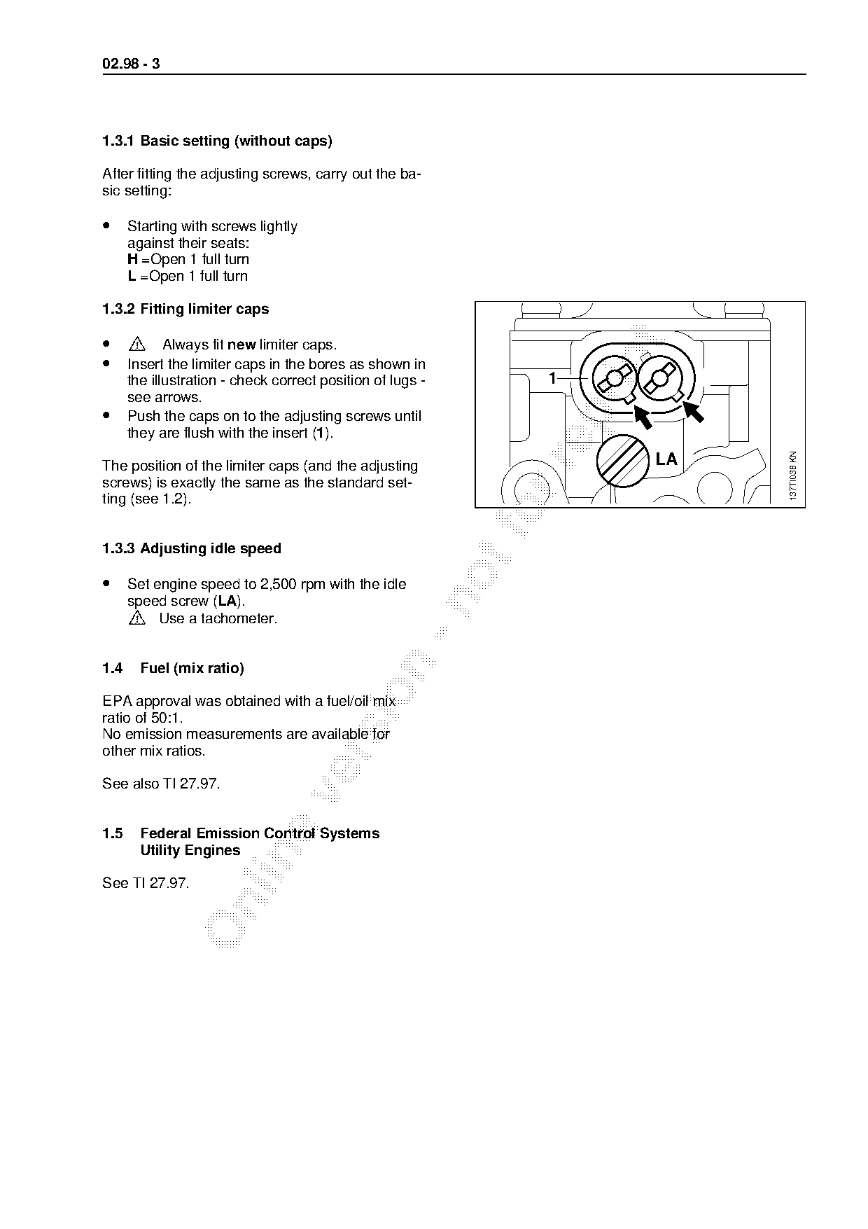
1.3.2 Fitting limiter caps

•     >=

        Always fit new limiter caps.
• Insert the limiter caps in the bores as shown in

      the illustration - check correct position of lugs -         1
      see arrows.
•

      Push the caps on to the adjusting screws until
      they are flush with the insert (1).

                                                                              137TI036 KN
                                                                         LA

The position of the limiter caps (and the adjusting
screws) is exactly the same as the standard set-
ting (see 1.2).
1.3.3 Adjusting idle speed
• Set engine speed to 2,500 rpm with the idle
      >
      speed screw (LA).

          Use a tachometer.

1.4     Fuel (mix ratio)

EPA approval was obtained with a fuel/oil mix
ratio of 50:1.
No emission measurements are available for
other mix ratios.

See also TI 27.97.

1.5     Federal Emission Control Systems
        Utility Engines

See TI 27.97.
Page 4 of 6
Text of page 4 — search, copy, screen readers
02.98 - 4

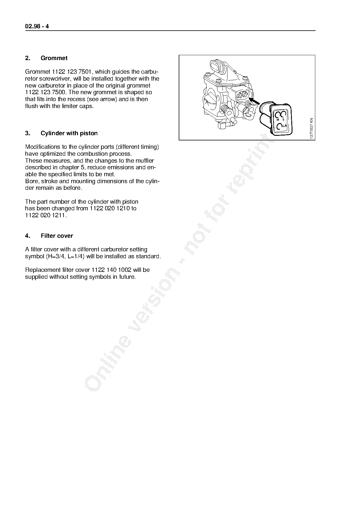
2.    Grommet

Grommet 1122 123 7501, which guides the carbu-
retor screwdriver, will be installed together with the
new carburetor in place of the original grommet
1122 123 7500. The new grommet is shaped so
that fits into the recess (see arrow) and is then
flush with the limiter caps.

                                                                                    137TI037 KN
                                                                           H   L


3.    Cylinder with piston

Modifications to the cylinder ports (different timing)

have optimized the combustion process.
These measures, and the changes to the muffler
described in chapter 5, reduce emissions and en-

able the specified limits to be met.
Bore, stroke and mounting dimensions of the cylin-
der remain as before.

The part number of the cylinder with piston
has been changed from 1122 020 1210 to
1122 020 1211.                                                fo
4.    Filter cover

A filter cover with a different carburetor setting
symbol (H=3/4, L=1/4) will be installed as standard.

Replacement filter cover 1122 140 1002 will be

supplied without setting symbols in future.
Page 5 of 6
Text of page 5 — search, copy, screen readers
02.98 - 5

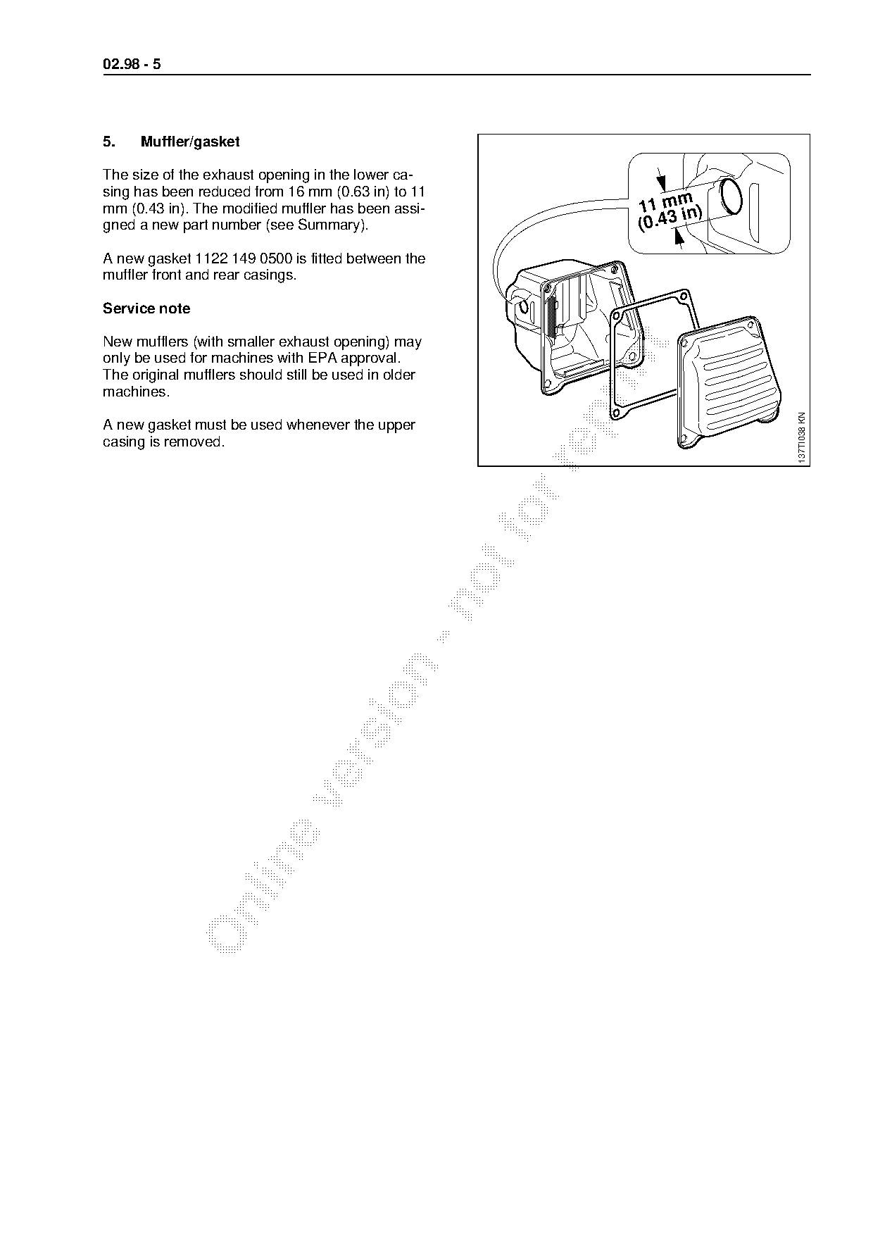
5.    Muffler/gasket

The size of the exhaust opening in the lower ca-
sing has been reduced from 16 mm (0.63 in) to 11
                                                                       m
mm (0.43 in). The modified muffler has been assi-                11 m in)
gned a new part number (see Summary).                            (0.43
A new gasket 1122 149 0500 is fitted between the
muffler front and rear casings.

Service note

New mufflers (with smaller exhaust opening) may

only be used for machines with EPA approval.

The original mufflers should still be used in older
machines.

                                                                            137TI038 KN
A new gasket must be used whenever the upper
casing is removed.
Page 6 of 6
Text of page 6 — search, copy, screen readers
02.98 - 6

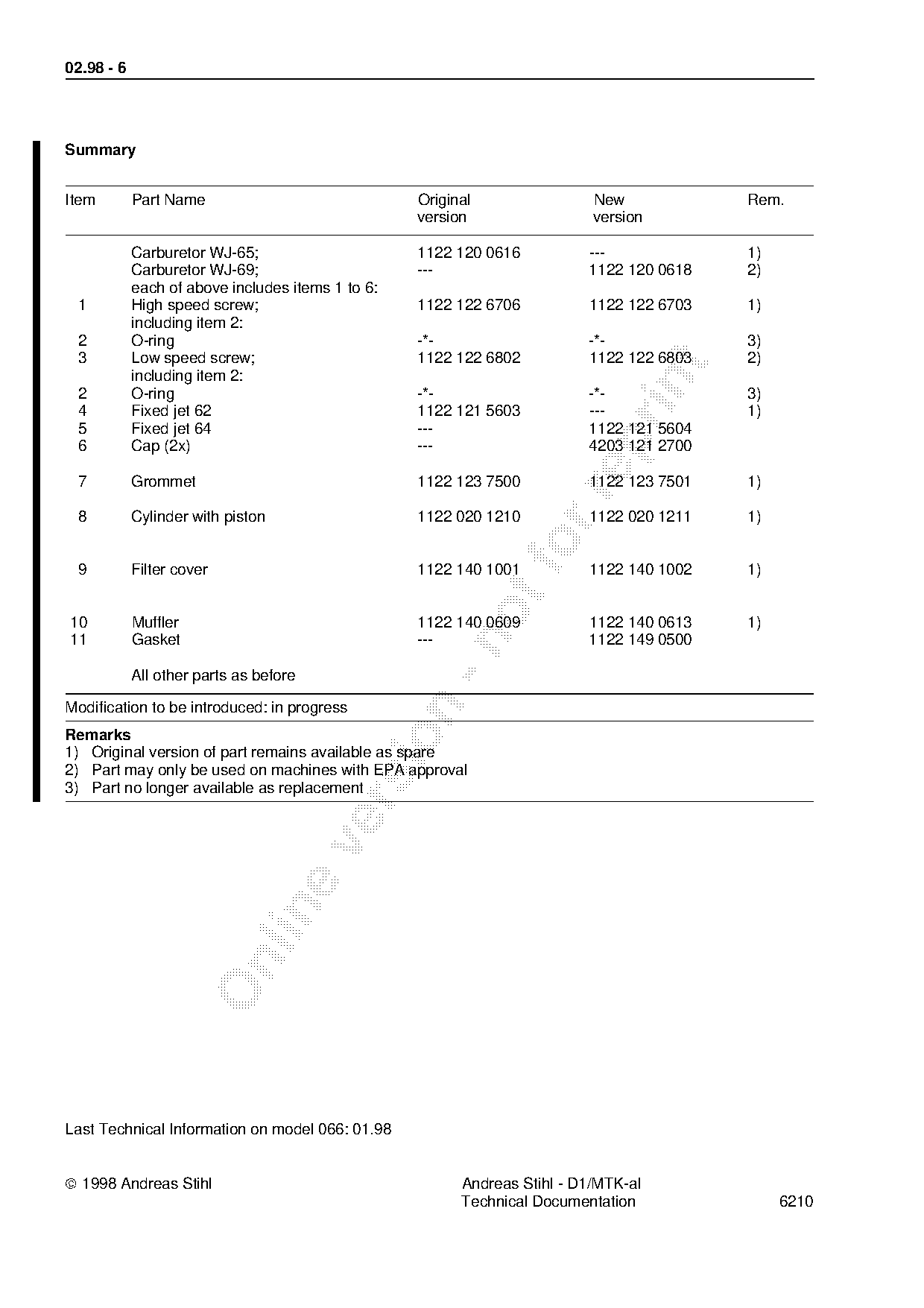
Summary

Item        Part Name                              Original                New            Rem.
                                                   version                 version

            Carburetor WJ-65;                      1122 120 0616          ---             1)
            Carburetor WJ-69;                      ---                    1122 120 0618   2)
            each of above includes items 1 to 6:
 1          High speed screw;                      1122 122 6706          1122 122 6703   1)
            including item 2:
 2          O-ring                                 -*-                    -*-             3)
 3          Low speed screw;                       1122 122 6802          1122 122 6803   2)

            including item 2:

 2          O-ring                                 -*-                    -*-             3)
 4          Fixed jet 62                           1122 121 5603          ---             1)
 5          Fixed jet 64                           ---                    1122 121 5604

 6          Cap (2x)                               ---                    4203 121 2700

 7          Grommet                                1122 123 7500          1122 123 7501   1)

 8          Cylinder with piston                   1122 020 1210          1122 020 1211   1)

 9          Filter cover                           1122 140 1001
                                                                fo        1122 140 1002   1)
10          Muffler                                1122 140 0609          1122 140 0613   1)
11          Gasket                                 ---                    1122 149 0500

            All other parts as before

Modification to be introduced: in progress

Remarks

1) Original version of part remains available as spare
2) Part may only be used on machines with EPA approval
3) Part no longer available as replacement

Last Technical Information on model 066: 01.98

ã 1998 Andreas Stihl                                     Andreas Stihl - D1/MTK-al
                                                         Technical Documentation               6210
Most of these PDFs embed fonts with a shifted character map, so the text above was recovered rather than copied — read it as a faithful but imperfect transcription, and treat the page image above each block as the authority where the two disagree — the figures exist only there, because they are vector drawings that text extraction cannot keep.