Technical Information · issue 5 of 1998
TS 350: Carburetor HL 366; cylinder with piston
IssueTI 5/1998
Part changes (1)
| Was | Becomes | What the bulletin says |
|---|---|---|
| 4201 120 0604 | 4201 120 0608 | Carburetor 4201 120 0604 (type HL 292 G) is replaced by version 4201 120 0608 (type HL 366). |
Full text
Page 1 of 4
Text of page 1 — search, copy, screen readers
Technical Information

                                                                                                     05.98

Cut-off machines STIHL TS 350 – type 4201

Contents

1. Carburetor HL 366

2. Cylinder with piston

Compliance with EPA regulations (see TI 27.97) is achieved with the modifications described below.
The factory applies the label shown below to all machines that conform to the latest standard.

               Andreas Stihl IMPORTANT ENGINE INFORMATION
    ENGINE FAMILY: A8XS.     R ; Type:    ; DISPL.:   CC;M.D.:
    THIS ENGINE CONFORMS TO U.S. EPA PHASE 1 EMISSION REGULATIONS

                                                                           000TI013 KN
    FOR ULGE´s. REFER TO OWNER´S MANUAL FOR MAINTENANCE

    SPECIFICATIONS AND ADJUSTMENT.                    967 34

1. Carburetor HL 366

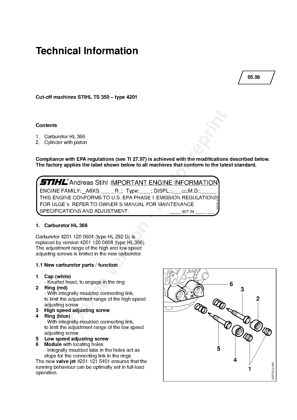
Carburetor 4201 120 0604 (type HL 292 G) is
replaced by version 4201 120 0608 (type HL 366).
The adjustment range of the high and low speed
adjusting screws is limited in the new carburetor.

1.1 New carburetor parts / function

1  Cap (white)
   - Knurled head, to engage in the ring                                                 6
2 Ring (red)                                                                                     3

   - With integrally moulded connecting link,
   to limit the adjustment range of the high speed                                                       2
   adjusting screw

3 High speed adjusting screw
4 Ring (blue)
   - With integrally moulded connecting link,
   to limit the adjustment range of the low speed
   adjusting screw
5 Low speed adjusting screw
6 Module with locating holes
   - Integrally moulded tabs in the holes act as                            5
   stops for the connecting link in the rings
The new valve jet 4201 121 5401 ensures that the                                             4
                                                                                                             330TI012 KN

running behaviour can be optimally set in full-load                                                  1
operation.
Page 2 of 4
Text of page 2 — search, copy, screen readers
05.98 - 2

1.2 Standard setting

The carburetor is set at the factory to provide an
optimum fuel-air mixture under all operating
conditions. It ensures that the machine will run
smoothly, be fuel efficient, operate reliably and
produce low emissions.
                                                                L H         LA
The setting is identical to the standard setting
described in the chapter entitled "Carburetor                           L
                                                                      1/4    H
                                                                            1/4
adjustment" in the Owner’s Manual:
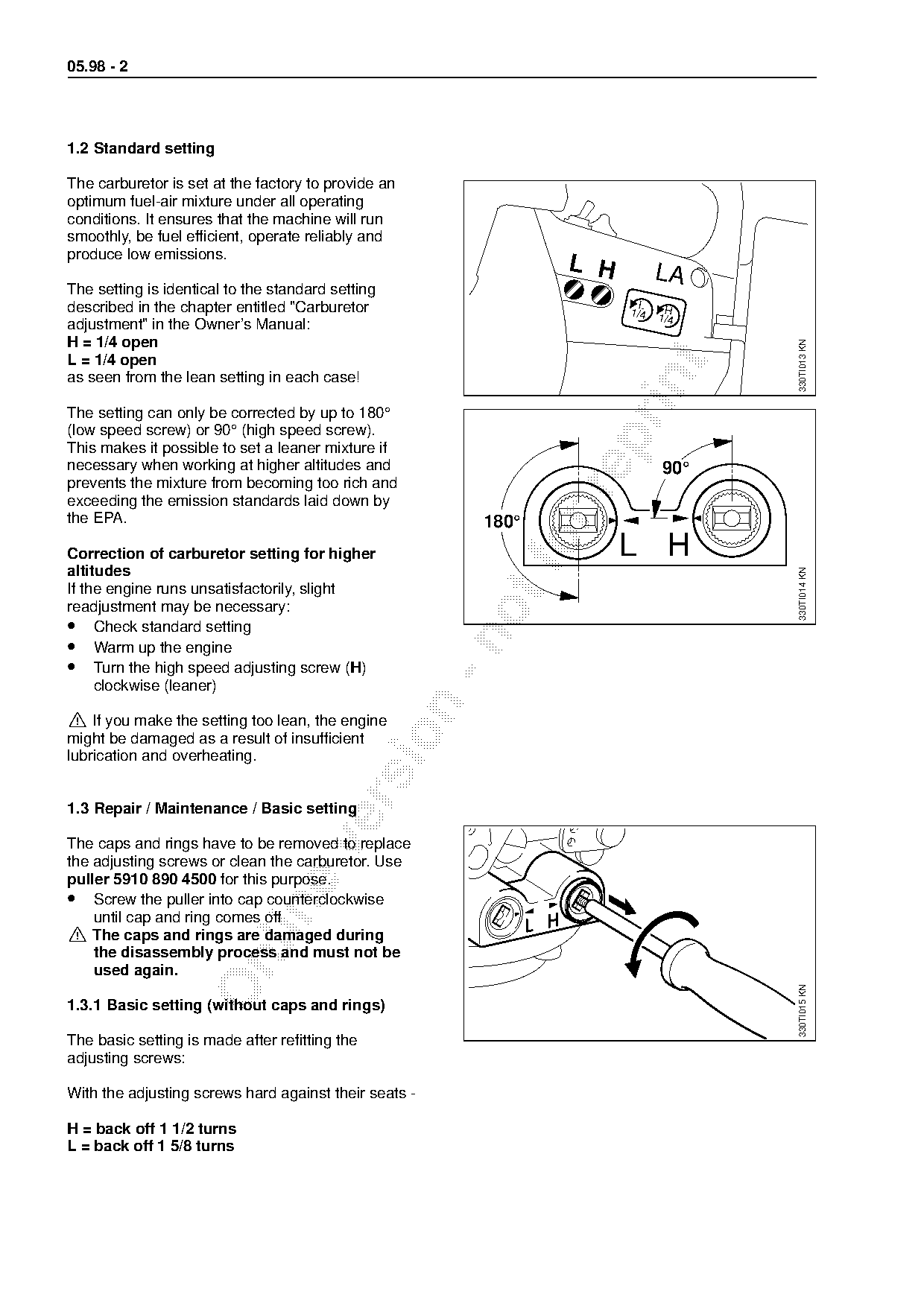
H = 1/4 open

                                                                                  330TI013 KN
L = 1/4 open

as seen from the lean setting in each case!

The setting can only be corrected by up to 180°
(low speed screw) or 90° (high speed screw).

This makes it possible to set a leaner mixture if
necessary when working at higher altitudes and                              90°
prevents the mixture from becoming too rich and

exceeding the emission standards laid down by
the EPA.                                                 180°
Correction of carburetor setting for higher
altitudes
                                                            fo        L H

                                                                                  330TI014 KN
If the engine runs unsatisfactorily, slight
readjustment may be necessary:
• Check standard setting

• Warm up the engine
• Turn the high speed adjusting screw (H)
     clockwise (leaner)

! If you make the setting too lean, the engine

might be damaged as a result of insufficient
lubrication and overheating.

1.3 Repair / Maintenance / Basic setting

The caps and rings have to be removed to replace
the adjusting screws or clean the carburetor. Use
puller 5910 890 4500 for this purpose.
• Screw the puller into cap counterclockwise

    until cap and ring comes off
! The caps and rings are damaged during
    the disassembly process and must not be

    used again.
                                                                                  330TI015 KN

1.3.1 Basic setting (without caps and rings)

The basic setting is made after refitting the
adjusting screws:

With the adjusting screws hard against their seats -

H = back off 1 1/2 turns
L = back off 1 5/8 turns
Page 3 of 4
Text of page 3 — search, copy, screen readers
05.98 - 3

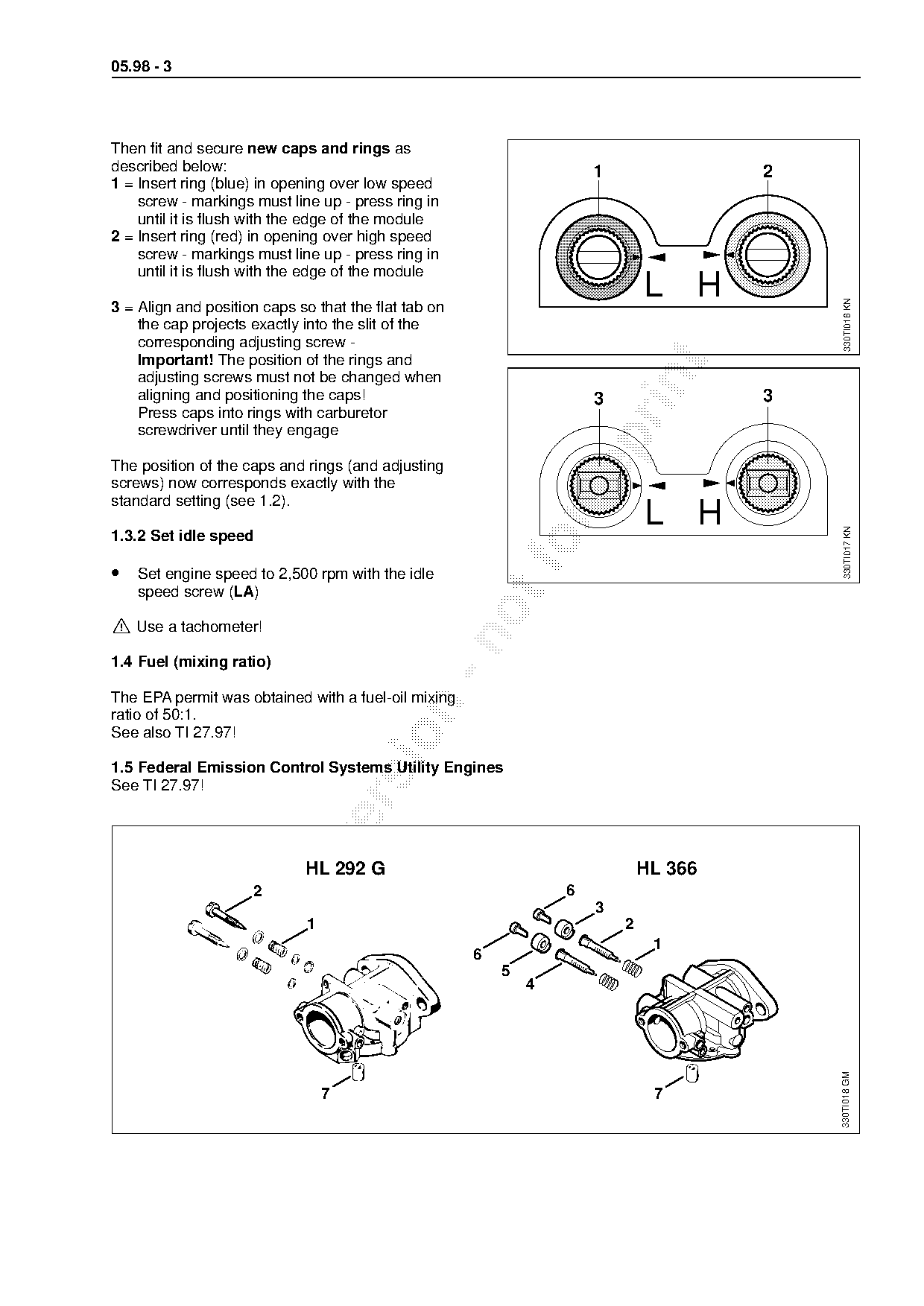
Then fit and secure new caps and rings as
described below:                                                      1                2
1 = Insert ring (blue) in opening over low speed
    screw - markings must line up - press ring in
    until it is flush with the edge of the module
2 = Insert ring (red) in opening over high speed
    screw - markings must line up - press ring in
    until it is flush with the edge of the module
                                                                              L H

                                                                                            330TI016 KN
3 = Align and position caps so that the flat tab on
    the cap projects exactly into the slit of the
    corresponding adjusting screw -
    Important! The position of the rings and

    adjusting screws must not be changed when

    aligning and positioning the caps!                                3                3
    Press caps into rings with carburetor
    screwdriver until they engage

The position of the caps and rings (and adjusting
screws) now corresponds exactly with the

standard setting (see 1.2).
                                                                              L H

                                                                                            330TI017 KN
1.3.2 Set idle speed

• Set engine speed to 2,500 rpm with the idle
    speed screw (LA)

! Use a tachometer!

1.4 Fuel (mixing ratio)

The EPA permit was obtained with a fuel-oil mixing

ratio of 50:1.
See also TI 27.97!

1.5 Federal Emission Control Systems Utility Engines
See TI 27.97!

                             HL 292 G                                         HL 366
                     2                                            6

                                                                      3
                             1                                            2
                                                                               1
                                                      6

                                                          5
                                                              4
                                                                                           330TI018 GM

                                 7                                             7
Page 4 of 4
Text of page 4 — search, copy, screen readers
05.98 - 4
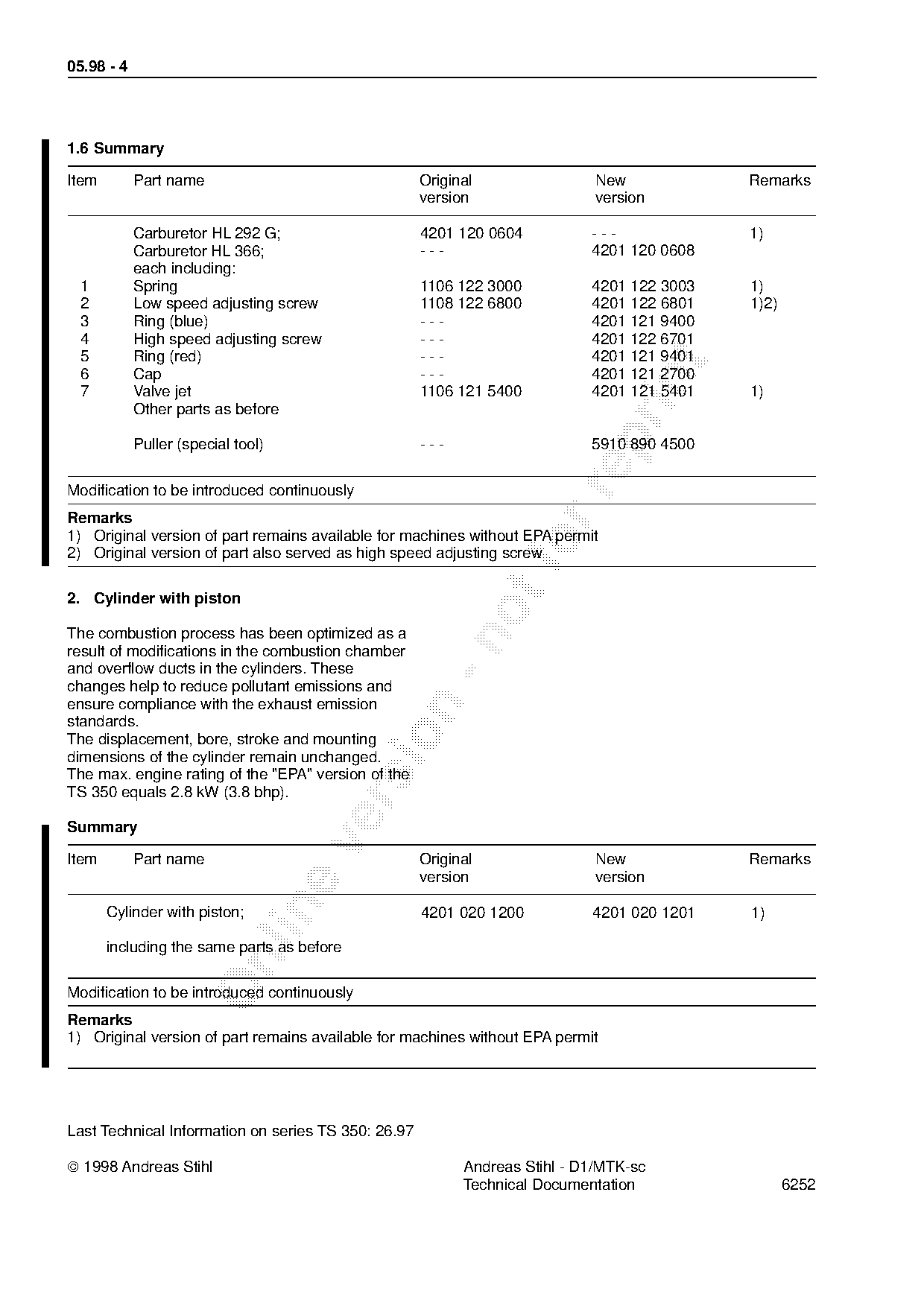
1.6 Summary
Item Part name Original New Remarks
version version
Carburetor HL 292 G; 4201 120 0604 --- 1)
Carburetor HL 366; --- 4201 120 0608
each including:
1 Spring 1106 122 3000 4201 122 3003 1)
2 Low speed adjusting screw 1108 122 6800 4201 122 6801 1)2)
3 Ring (blue) --- 4201 121 9400
4 High speed adjusting screw --- 4201 122 6701
5 Ring (red) --- 4201 121 9401
6 Cap --- 4201 121 2700
7 Valve jet 1106 121 5400 4201 121 5401 1)
Other parts as before
Puller (special tool) --- 5910 890 4500
Modification to be introduced continuously
Remarks
1) Original version of part remains available for machines without EPA permit
2) Original version of part also served as high speed adjusting screw
2. Cylinder with piston
The combustion process has been optimized as a
result of modifications in the combustion chamber
and overflow ducts in the cylinders. These
changes help to reduce pollutant emissions and
ensure compliance with the exhaust emission
standards.
The displacement, bore, stroke and mounting
dimensions of the cylinder remain unchanged.
The max. engine rating of the "EPA" version of the
TS 350 equals 2.8 kW (3.8 bhp).
Summary
Item Part name Original New Remarks
version version
Cylinder with piston; 4201 020 1200 4201 020 1201 1)
including the same parts as before
Modification to be introduced continuously
Remarks
1) Original version of part remains available for machines without EPA permit
Last Technical Information on series TS 350: 26.97
1998 Andreas Stihl Andreas Stihl - D1/MTK-sc
Technical Documentation 6252 Most of these PDFs embed fonts with a shifted character map, so the text above was recovered rather than copied — read it as a faithful but imperfect transcription, and treat the page image above each block as the authority where the two disagree — the figures exist only there, because they are vector drawings that text extraction cannot keep.