Technical Information · issue 14 of 1998
FS 25, FS 65-4: New Brushcutters with 4-Stroke Eng
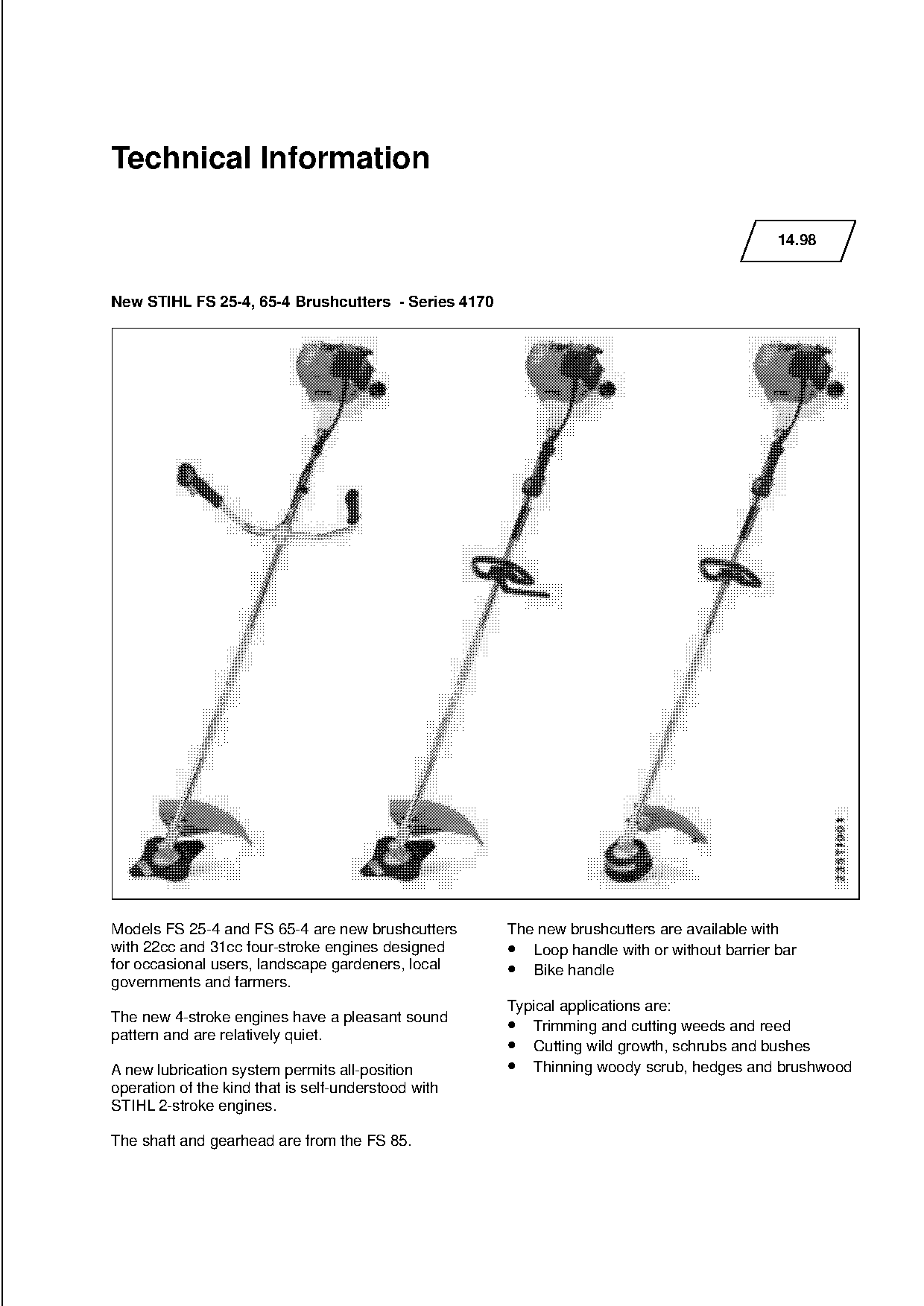
Models FS 25-4 and FS 65-4 are new brushcutters The new brushcutters are available with
IssueTI 14/1998
Full text
Page 1 of 8
Text of page 1 — search, copy, screen readers
Technical Information

                                                                                           14.98

New STIHL FS 25-4, 65-4 Brushcutters - Series 4170

Models FS 25-4 and FS 65-4 are new brushcutters      The new brushcutters are available with
with 22cc and 31cc four-stroke engines designed      • Loop handle with or without barrier bar

for occasional users, landscape gardeners, local     • Bike handle
governments and farmers.
                                                     Typical applications are:
The new 4-stroke engines have a pleasant sound
pattern and are relatively quiet.
                                                     • Trimming and cutting weeds and reed
                                                     • Cutting wild growth, schrubs and bushes
A new lubrication system permits all-position        • Thinning woody scrub, hedges and brushwood
operation of the kind that is self-understood with
STIHL 2-stroke engines.

The shaft and gearhead are from the FS 85.
Page 2 of 8
Text of page 2 — search, copy, screen readers
14.98 - 2

Contents

1. Technical description                               4.   Special accessories for user
2. Specifications                                      5.   Accessories for service
3. Cutting tools                                       6.   Repairs

1. Technical description

1.1 Engine

1.1.1 Weight and size

The weight and overall size of the STIHL single

cylinder 4-stroke engine have been optimized in
the compact design concept.

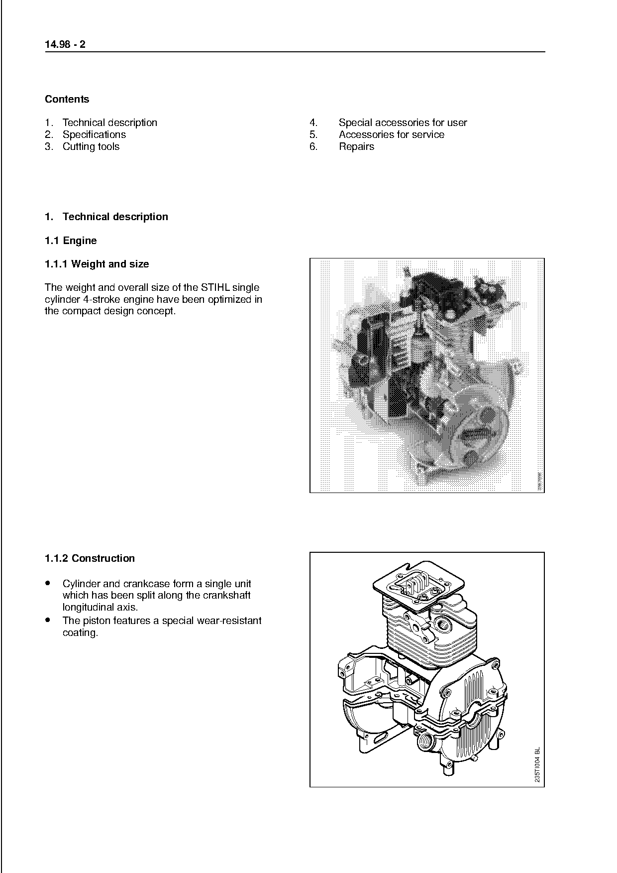
1.1.2 Construction

• Cylinder and crankcase form a single unit
    which has been split along the crankshaft

    longitudinal axis.
•   The piston features a special wear-resistant
    coating.

                                                                                           235TI004 BL
Page 3 of 8
Text of page 3 — search, copy, screen readers
14.98 - 3

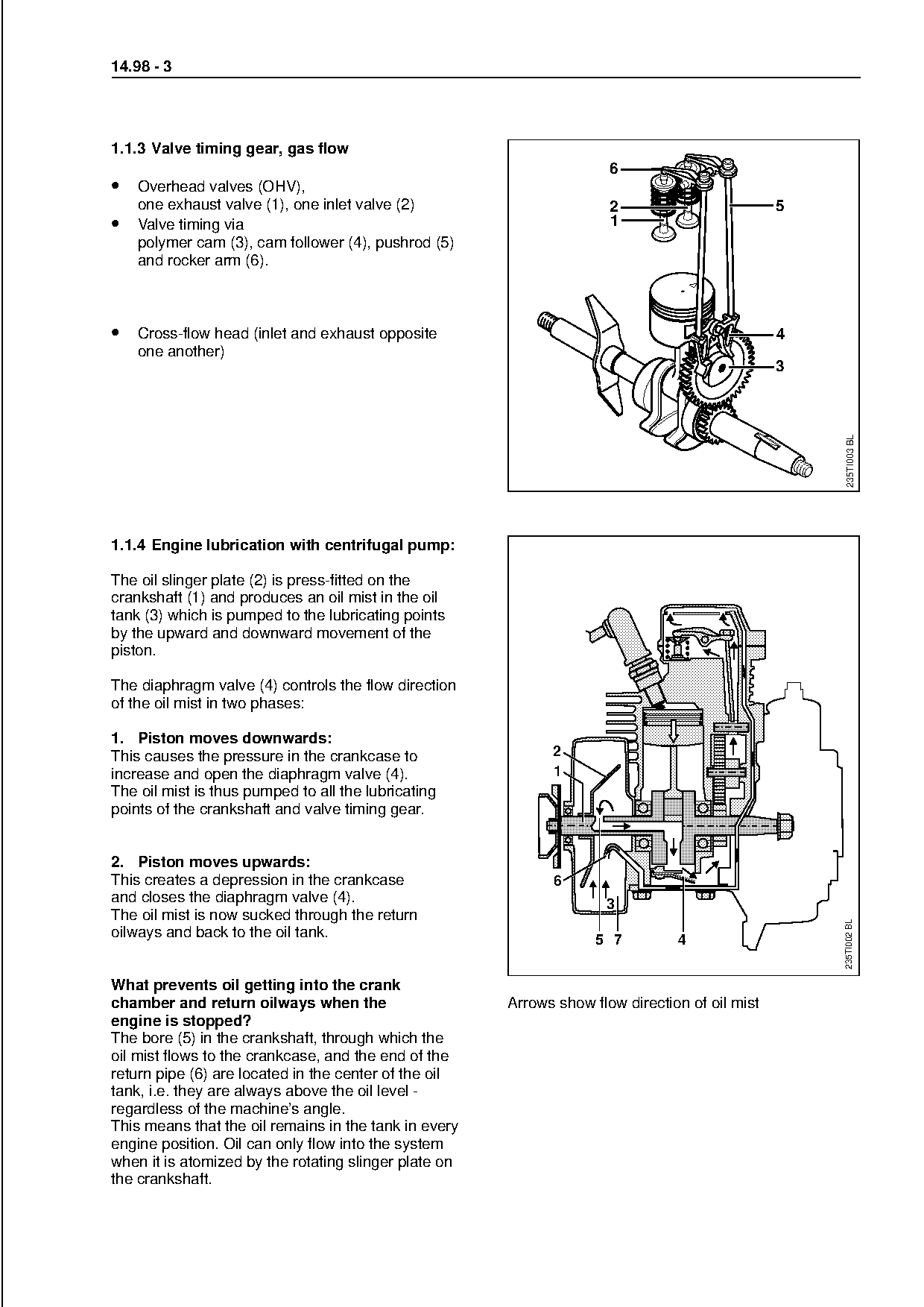
1.1.3 Valve timing gear, gas flow
                                                                      6
• Overhead valves (OHV),
    one exhaust valve (1), one inlet valve (2)                        2                         5
•   Valve timing via                                                  1
    polymer cam (3), cam follower (4), pushrod (5)
    and rocker arm (6).

• Cross-flow head (inlet and exhaust opposite                                                   4
    one another)


                                                                                                     235TI003 BL
1.1.4 Engine lubrication with centrifugal pump:           fo
The oil slinger plate (2) is press-fitted on the
crankshaft (1) and produces an oil mist in the oil
tank (3) which is pumped to the lubricating points
by the upward and downward movement of the

piston.

The diaphragm valve (4) controls the flow direction
of the oil mist in two phases:

1. Piston moves downwards:
This causes the pressure in the crankcase to                 2
increase and open the diaphragm valve (4).                   1
The oil mist is thus pumped to all the lubricating

points of the crankshaft and valve timing gear.

2. Piston moves upwards:
This creates a depression in the crankcase                   6
and closes the diaphragm valve (4).                                  3

The oil mist is now sucked through the return
                                                                                                    235TI002 BL

oilways and back to the oil tank.                                   5 7         4

What prevents oil getting into the crank
chamber and return oilways when the                    Arrows show flow direction of oil mist
engine is stopped?
The bore (5) in the crankshaft, through which the
oil mist flows to the crankcase, and the end of the
return pipe (6) are located in the center of the oil
tank, i.e. they are always above the oil level -
regardless of the machine’s angle.
This means that the oil remains in the tank in every
engine position. Oil can only flow into the system
when it is atomized by the rotating slinger plate on
the crankshaft.
Page 4 of 8
Text of page 4 — search, copy, screen readers
14.98 - 4

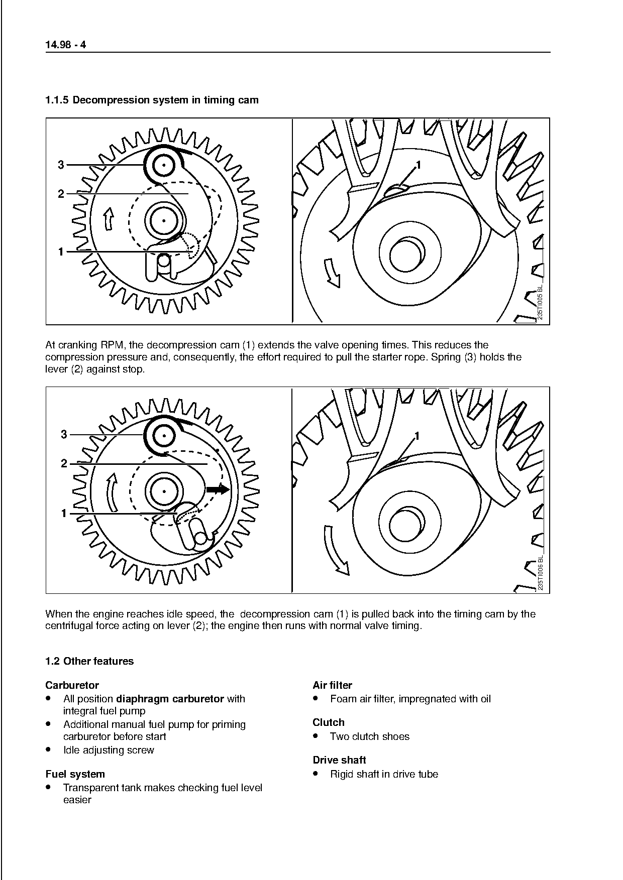
1.1.5 Decompression system in timing cam

  3                                                                               1


                                                                                                             235TI005 BL
At cranking RPM, the decompression cam (1) extends the valve opening times. This reduces the
compression pressure and, consequently, the effort required to pull the starter rope. Spring (3) holds the
lever (2) against stop.                                             fo

   3                                                                              1


                                                                                                             235TI006 BL

When the engine reaches idle speed, the decompression cam (1) is pulled back into the timing cam by the
centrifugal force acting on lever (2); the engine then runs with normal valve timing.

1.2 Other features

Carburetor                                                 Air filter
• All position diaphragm carburetor with                   • Foam air filter, impregnated with oil
   integral fuel pump
• Additional manual fuel pump for priming                  Clutch
   carburetor before start                                 • Two clutch shoes
• Idle adjusting screw
                                                           Drive shaft
Fuel system                                                • Rigid shaft in drive tube
• Transparent tank makes checking fuel level
   easier
Page 5 of 8
Text of page 5 — search, copy, screen readers
14.98 - 5

1.3 Controls
• Multi-function handle with soft, non-slip grip
    surface

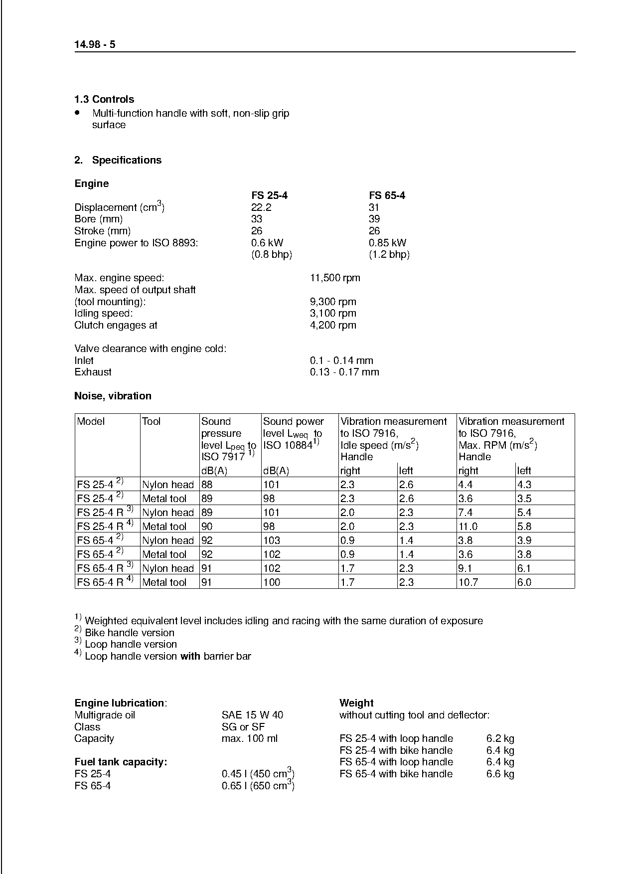
2. Specifications

Engine
                                       FS 25-4                  FS 65-4
Displacement (cm3)                     22.2                     31
Bore (mm)                              33                       39
Stroke (mm)                            26                       26
Engine power to ISO 8893:              0.6 kW                   0.85 kW

                                       (0.8 bhp)                (1.2 bhp)

Max. engine speed:                                 11,500 rpm
Max. speed of output shaft

(tool mounting):                                   9,300 rpm
Idling speed:                                      3,100 rpm
Clutch engages at                                  4,200 rpm

Valve clearance with engine cold:
Inlet                                              0.1 - 0.14 mm
Exhaust                                                    fo
                                                   0.13 - 0.17 mm

Noise, vibration

Model          Tool       Sound         Sound power       Vibration measurement      Vibration measurement

                          pressure      level Lweq to     to ISO 7916,               to ISO 7916,
                          level Lpeq to ISO 108841)       Idle speed (m/s2)          Max. RPM (m/s2)
                          ISO 7917 1)                     Handle                     Handle
                          dB(A)         dB(A)             right        left          right        left

FS 25-4 2)     Nylon head 88            101               2.3          2.6           4.4          4.3

FS 25-4 2)     Metal tool 89            98                2.3          2.6           3.6          3.5
FS 25-4 R 3)   Nylon head 89            101               2.0          2.3           7.4          5.4
FS 25-4 R 4)   Metal tool 90            98                2.0          2.3           11.0         5.8

FS 65-4 2)     Nylon head 92            103               0.9          1.4           3.8          3.9
FS 65-4 2)     Metal tool 92            102               0.9          1.4           3.6          3.8

FS 65-4 R 3)   Nylon head 91            102               1.7          2.3           9.1          6.1
FS 65-4 R 4)   Metal tool 91            100               1.7          2.3           10.7         6.0

1)
   Weighted equivalent level includes idling and racing with the same duration of exposure
2)
   Bike handle version
3)

   Loop handle version
4)
  Loop handle version with barrier bar

Engine lubrication:                                       Weight
Multigrade oil                  SAE 15 W 40               without cutting tool and deflector:
Class                           SG or SF
Capacity                        max. 100 ml               FS 25-4 with loop handle           6.2 kg
                                                          FS 25-4 with bike handle           6.4 kg
Fuel tank capacity:                                       FS 65-4 with loop handle           6.4 kg
FS 25-4                         0.45 l (450 cm3)          FS 65-4 with bike handle           6.6 kg
FS 65-4                         0.65 l (650 cm3)
Page 6 of 8
Text of page 6 — search, copy, screen readers
14.98 - 6

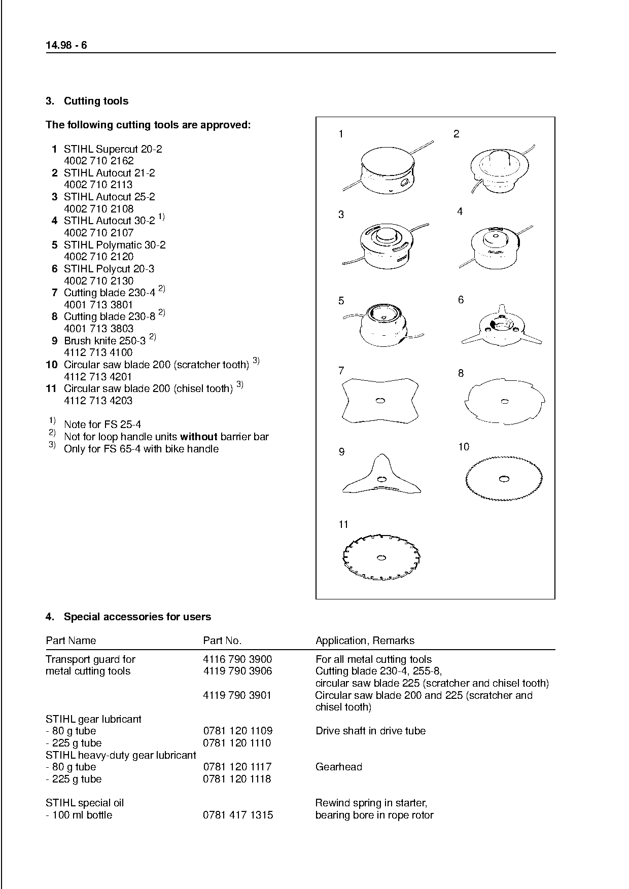
3. Cutting tools

The following cutting tools are approved:
                                                              1                                 2
 1 STIHL Supercut 20-2
   4002 710 2162

                                                                                     681FK003
 2 STIHL Autocut 21-2
   4002 710 2113
 3 STIHL Autocut 25-2
   4002 710 2108                                                                                4
                                                              3
 4 STIHL Autocut 30-2 1)
   4002 710 2107
 5 STIHL Polymatic 30-2

                                                                                                        681FK007
   4002 710 2120

 6 STIHL Polycut 20-3
   4002 710 2130
 7 Cutting blade 230-4 2)

   4001 713 3801                                              5                                 6
 8 Cutting blade 230-8 2)
   4001 713 3803

 9 Brush knife 250-3 2)
   4112 713 4100
10 Circular saw blade 200 (scratcher tooth) 3)
   4112 713 4201
11 Circular saw blade 200 (chisel tooth) 3)
                                                              7    fo                           8

   4112 713 4203
1)
     Note for FS 25-4
2)

     Not for loop handle units without barrier bar
3)                                                                                              10
     Only for FS 65-4 with bike handle                        9


4. Special accessories for users

Part Name                          Part No.              Application, Remarks

Transport guard for                4116 790 3900         For all metal cutting tools
metal cutting tools                4119 790 3906         Cutting blade 230-4, 255-8,
                                                         circular saw blade 225 (scratcher and chisel tooth)
                                   4119 790 3901         Circular saw blade 200 and 225 (scratcher and
                                                         chisel tooth)
STIHL gear lubricant
- 80 g tube                     0781 120 1109            Drive shaft in drive tube
- 225 g tube                    0781 120 1110
STIHL heavy-duty gear lubricant
- 80 g tube                     0781 120 1117            Gearhead
- 225 g tube                    0781 120 1118

STIHL special oil                                        Rewind spring in starter,
- 100 ml bottle                    0781 417 1315         bearing bore in rope rotor
Page 7 of 8
Text of page 7 — search, copy, screen readers
14.98 - 7

4.1 Nylon line for cutting heads

Line diameter                      For use with
/ color
2.4 mm / orange                    Supercut 20-2, Autocut 21-2, Autocut 25-2, Autocut 30-2,
                                   Polymatic 30-2, Polycut 20-3
2.7 mm / red                       Polycut 20-3

4.2 Sharpening aids for metal cutting tools

Part Name                          Part No.               Application

Saw set                            4020 893 5000          Circular saw blade 200 and 225 (chisel tooth)

Sharpening template                4020 890 5500          Brush knife

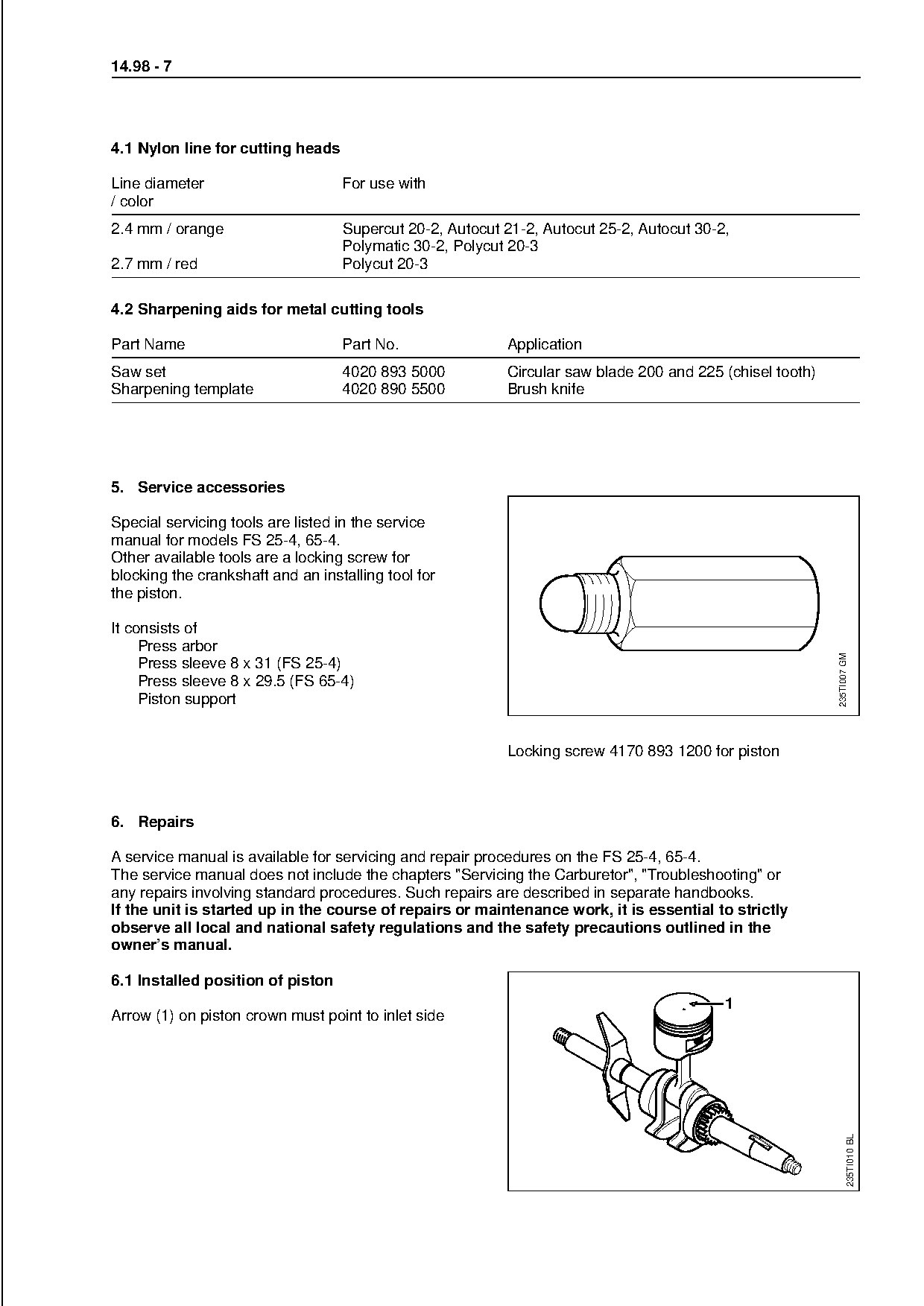
5. Service accessories

Special servicing tools are listed in the service
manual for models FS 25-4, 65-4.
Other available tools are a locking screw for
blocking the crankshaft and an installing tool for
the piston.

It consists of

     Press arbor

                                                                                                          235TI007 GM
     Press sleeve 8 x 31 (FS 25-4)
     Press sleeve 8 x 29.5 (FS 65-4)
     Piston support

                                                          Locking screw 4170 893 1200 for piston

6. Repairs

A service manual is available for servicing and repair procedures on the FS 25-4, 65-4.
The service manual does not include the chapters "Servicing the Carburetor", "Troubleshooting" or
any repairs involving standard procedures. Such repairs are described in separate handbooks.

If the unit is started up in the course of repairs or maintenance work, it is essential to strictly
observe all local and national safety regulations and the safety precautions outlined in the
owner’s manual.

6.1 Installed position of piston
                                                                                          1
Arrow (1) on piston crown must point to inlet side
                                                                                                                    235TI010 BL
Page 8 of 8
Text of page 8 — search, copy, screen readers
14.98 - 8
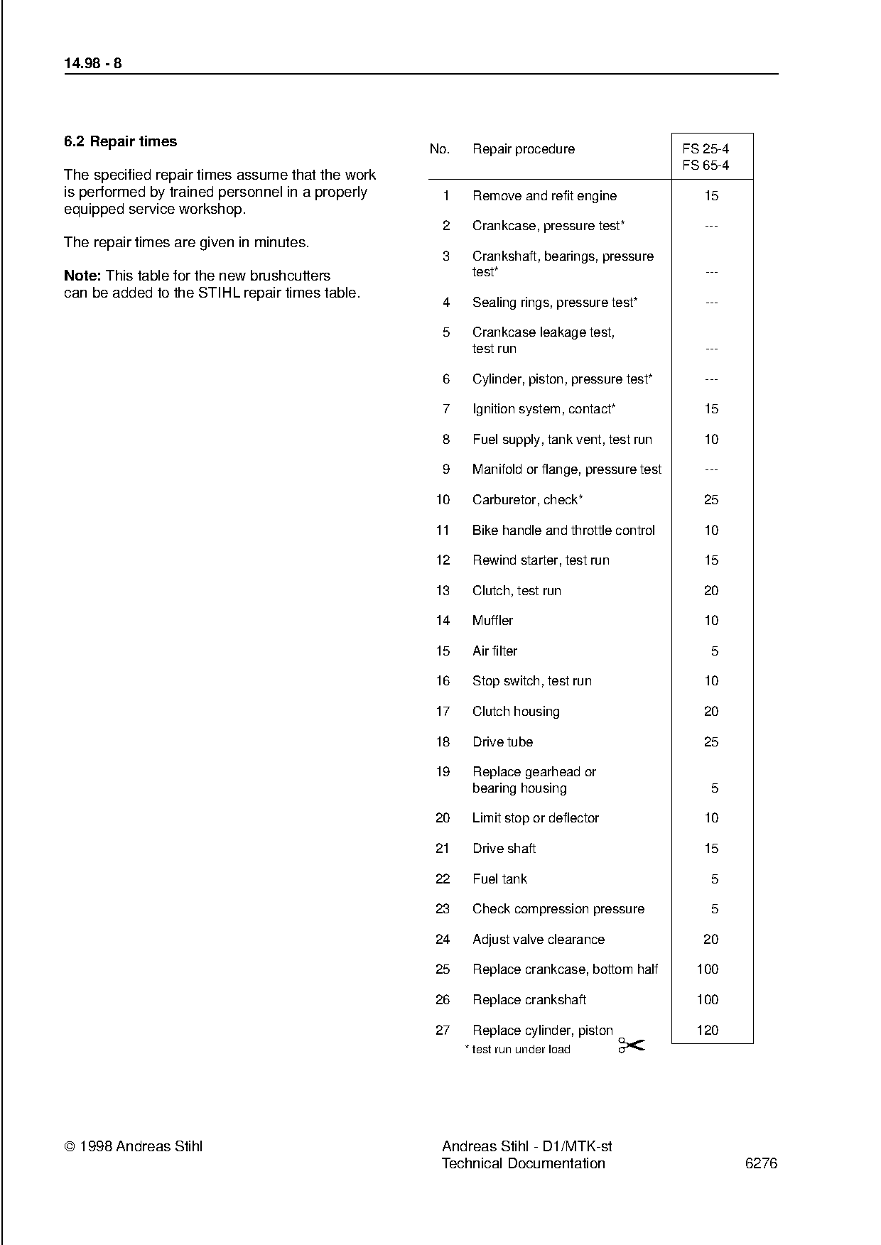
6.2 Repair times
No. Repair procedure FS 25-4
FS 65-4
The specified repair times assume that the work
is performed by trained personnel in a properly 1 Remove and refit engine 15
equipped service workshop.
2 Crankcase, pressure test* ---
The repair times are given in minutes.
3 Crankshaft, bearings, pressure
Note: This table for the new brushcutters test* ---
can be added to the STIHL repair times table.
4 Sealing rings, pressure test* ---
5 Crankcase leakage test,
test run ---
6 Cylinder, piston, pressure test* ---
7 Ignition system, contact* 15
8 Fuel supply, tank vent, test run 10
9 Manifold or flange, pressure test ---
10 Carburetor, check* 25
11 fo
Bike handle and throttle control 10
12 Rewind starter, test run 15
13 Clutch, test run 20
14 Muffler 10
15 Air filter 5
16 Stop switch, test run 10
17 Clutch housing 20
18 Drive tube 25
19 Replace gearhead or
bearing housing 5
20 Limit stop or deflector 10
21 Drive shaft 15
22 Fuel tank 5
23 Check compression pressure 5
24 Adjust valve clearance 20
25 Replace crankcase, bottom half 100
26 Replace crankshaft 100
27 Replace cylinder, piston 120
* test run under load ✂
1998 Andreas Stihl Andreas Stihl - D1/MTK-st
Technical Documentation 6276 Most of these PDFs embed fonts with a shifted character map, so the text above was recovered rather than copied — read it as a faithful but imperfect transcription, and treat the page image above each block as the authority where the two disagree — the figures exist only there, because they are vector drawings that text extraction cannot keep.