Technical Information · issue 20 of 1998
Gearhead; Handle System; Service Notes; Muffler
Model FS 300, FS 350 Clearing Saws - Series 4134
IssueTI 20/1998
Part changes (1)
| Was | Becomes | What the bulletin says |
|---|---|---|
| 0000 997 1302 | 0000 997 1304 | The original helical spring 0000 997 1302, installed between the two moldings of the handlebar clamp, will be replaced by helical spring 0000 997 1304. |
Full text
Page 1 of 4
Text of page 1 — search, copy, screen readers
Technical Information

                                                                                       20.98

Model FS 300, FS 350 Clearing Saws                     - Series 4134
Model FS 400, FS 450 Clearing Saws                     - Series 4128

Contents

1.   Gearhead (gear ratio)
2.   Handle system (helical spring)

3.   Service notes (gearhead mounting, special tool)
4.   Muffler (FS 300, 350)

1. Gearhead

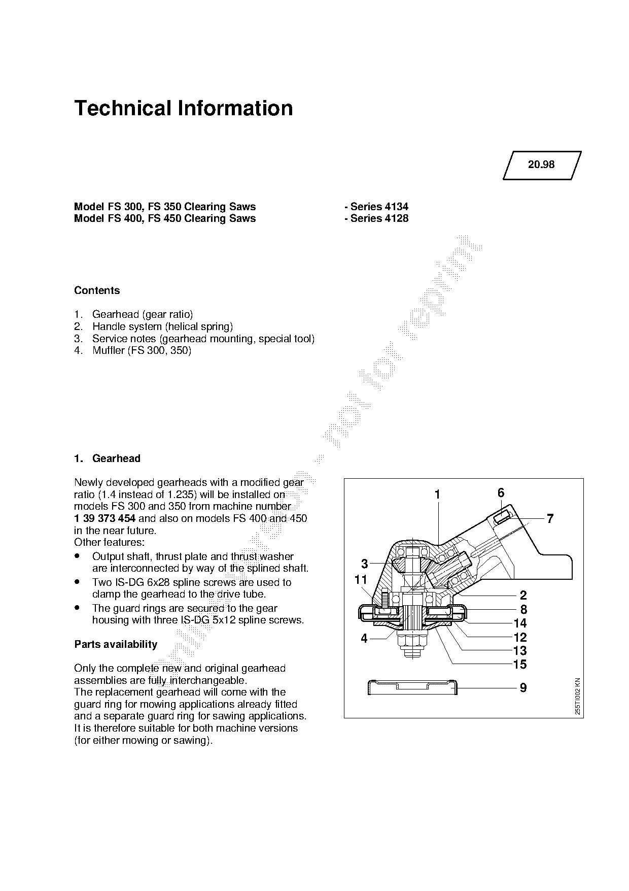
Newly developed gearheads with a modified gear
ratio (1.4 instead of 1.235) will be installed on                      1      6

models FS 300 and 350 from machine number
1 39 373 454 and also on models FS 400 and 450                                            7
in the near future.
Other features:

• Output shaft, thrust plate and thrust washer
     are interconnected by way of the splined shaft.      3

• Two IS-DG 6x28 spline screws are used to               11
     clamp the gearhead to the drive tube.                                         2
• The guard rings are secured to the gear                                          8

     housing with three IS-DG 5x12 spline screws.                                 14
Parts availability                                        4                       12
                                                                                  13

Only the complete new and original gearhead                                       15
assemblies are fully interchangeable.
                                                                                               255TI002 KN

The replacement gearhead will come with the                                       9
guard ring for mowing applications already fitted
and a separate guard ring for sawing applications.
It is therefore suitable for both machine versions
(for either mowing or sawing).
Page 2 of 4
Text of page 2 — search, copy, screen readers
20.98 - 2

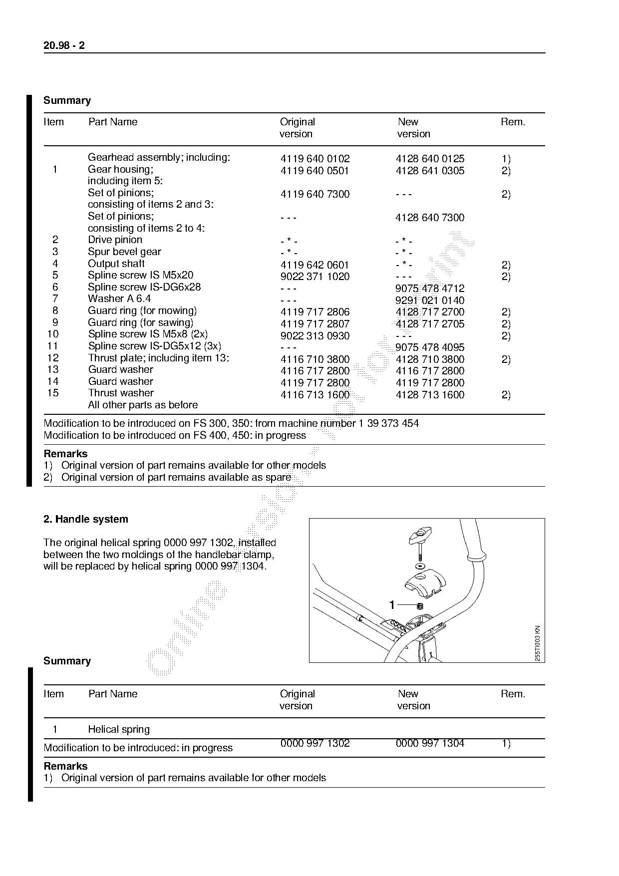
Summary

Item        Part Name                                  Original             New          Rem.
                                                       version              version

            Gearhead assembly; including:              4119 640 0102     4128 640 0125   1)
  1         Gear housing;                              4119 640 0501     4128 641 0305   2)
            including item 5:
            Set of pinions;                            4119 640 7300     ---             2)
            consisting of items 2 and 3:
            Set of pinions;                            ---               4128 640 7300
            consisting of items 2 to 4:
 2          Drive pinion                               -*-               -*-

 3          Spur bevel gear                            -*-               -*-

 4          Output shaft                               4119 642 0601     -*-             2)
 5          Spline screw IS M5x20                      9022 371 1020     ---             2)
 6          Spline screw IS-DG6x28                     ---               9075 478 4712

 7          Washer A 6.4                               ---               9291 021 0140
 8          Guard ring (for mowing)                    4119 717 2806     4128 717 2700   2)
 9          Guard ring (for sawing)                    4119 717 2807     4128 717 2705   2)

10          Spline screw IS M5x8 (2x)                  9022 313 0930     ---             2)
11          Spline screw IS-DG5x12 (3x)                ---               9075 478 4095
12          Thrust plate; including item 13:           4116 710 3800     4128 710 3800   2)
13
14
            Guard washer
            Guard washer
                                                       4116 717 2800
                                                       4119 717 2800
                                                                         4116 717 2800
                                                                         4119 717 2800
15          Thrust washer                              4116 713 1600     4128 713 1600   2)
            All other parts as before
Modification to be introduced on FS 300, 350: from machine number 1 39 373 454

Modification to be introduced on FS 400, 450: in progress
Remarks
1) Original version of part remains available for other models

2) Original version of part remains available as spare

2. Handle system

The original helical spring 0000 997 1302, installed
between the two moldings of the handlebar clamp,

will be replaced by helical spring 0000 997 1304.


                                                                                                255TI003 KN

Summary

Item        Part Name                                  Original             New          Rem.
                                                       version              version

  1         Helical spring
Modification to be introduced: in progress             0000 997 1302     0000 997 1304   1)

Remarks
1) Original version of part remains available for other models
Page 3 of 4
Text of page 3 — search, copy, screen readers
20.98 - 3

3. Service notes

3.1 Gearhead mounting

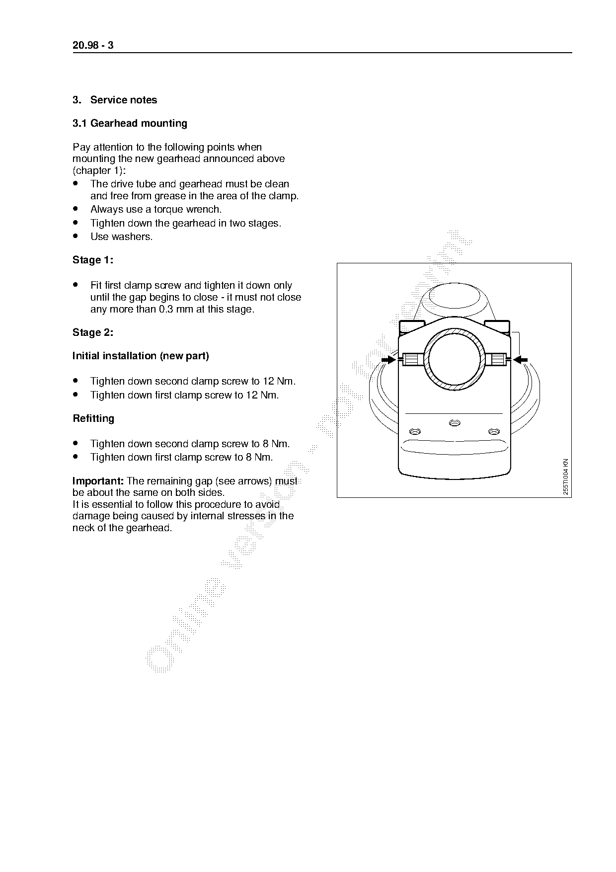
Pay attention to the following points when
mounting the new gearhead announced above
(chapter 1):
• The drive tube and gearhead must be clean
    and free from grease in the area of the clamp.
• Always use a torque wrench.
• Tighten down the gearhead in two stages.
• Use washers.

Stage 1:

• Fit first clamp screw and tighten it down only

    until the gap begins to close - it must not close
    any more than 0.3 mm at this stage.

Stage 2:

Initial installation (new part)

• Tighten down second clamp screw to 12 Nm.
• Tighten down first clamp screw to 12 Nm.

Refitting

• Tighten down second clamp screw to 8 Nm.
• Tighten down first clamp screw to 8 Nm.

                                                                      255TI004 KN

Important: The remaining gap (see arrows) must

be about the same on both sides.
It is essential to follow this procedure to avoid
damage being caused by internal stresses in the
neck of the gearhead.
Page 4 of 4
Text of page 4 — search, copy, screen readers
20.98 - 4

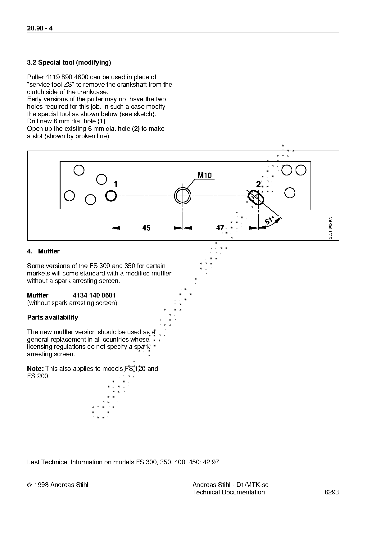
3.2 Special tool (modifying)

Puller 4119 890 4600 can be used in place of
"service tool ZS" to remove the crankshaft from the
clutch side of the crankcase.
Early versions of the puller may not have the two
holes required for this job. In such a case modify
the special tool as shown below (see sketch).
Drill new 6 mm dia. hole (1).
Open up the existing 6 mm dia. hole (2) to make
a slot (shown by broken line).

                                                         M10

                               1                                           2

                                                                                   °

                                                                                        255TI005 KN
                                                                               51
                                        45                     fo
                                                               47
4. Muffler

Some versions of the FS 300 and 350 for certain

markets will come standard with a modified muffler
without a spark arresting screen.

Muffler         4134 140 0601
(without spark arresting screen)

Parts availability

The new muffler version should be used as a

general replacement in all countries whose
licensing regulations do not specify a spark

arresting screen.

Note: This also applies to models FS 120 and
FS 200.

Last Technical Information on models FS 300, 350, 400, 450: 42.97

ã 1998 Andreas Stihl                                   Andreas Stihl - D1/MTK-sc
                                                       Technical Documentation         6293
Most of these PDFs embed fonts with a shifted character map, so the text above was recovered rather than copied — read it as a faithful but imperfect transcription, and treat the page image above each block as the authority where the two disagree — the figures exist only there, because they are vector drawings that text extraction cannot keep.