Technical Information · issue 2 of 1999
FS 45: New Model Brushcutters
Model Tool Sound Sound Vibration- Vibration
IssueTI 2/1999
Full text
Page 1 of 6
Text of page 1 — search, copy, screen readers
Technical Information

                                                                    02.1
New Model FS 45 Brushcutters  -  Series 4140

&RQWHQWV
1. Technical Description
2. Specifications

3. Cutting Tool
4. Special Accessories for Users
5. Service Accessories
6. Repairs

7. Spare Parts
1.

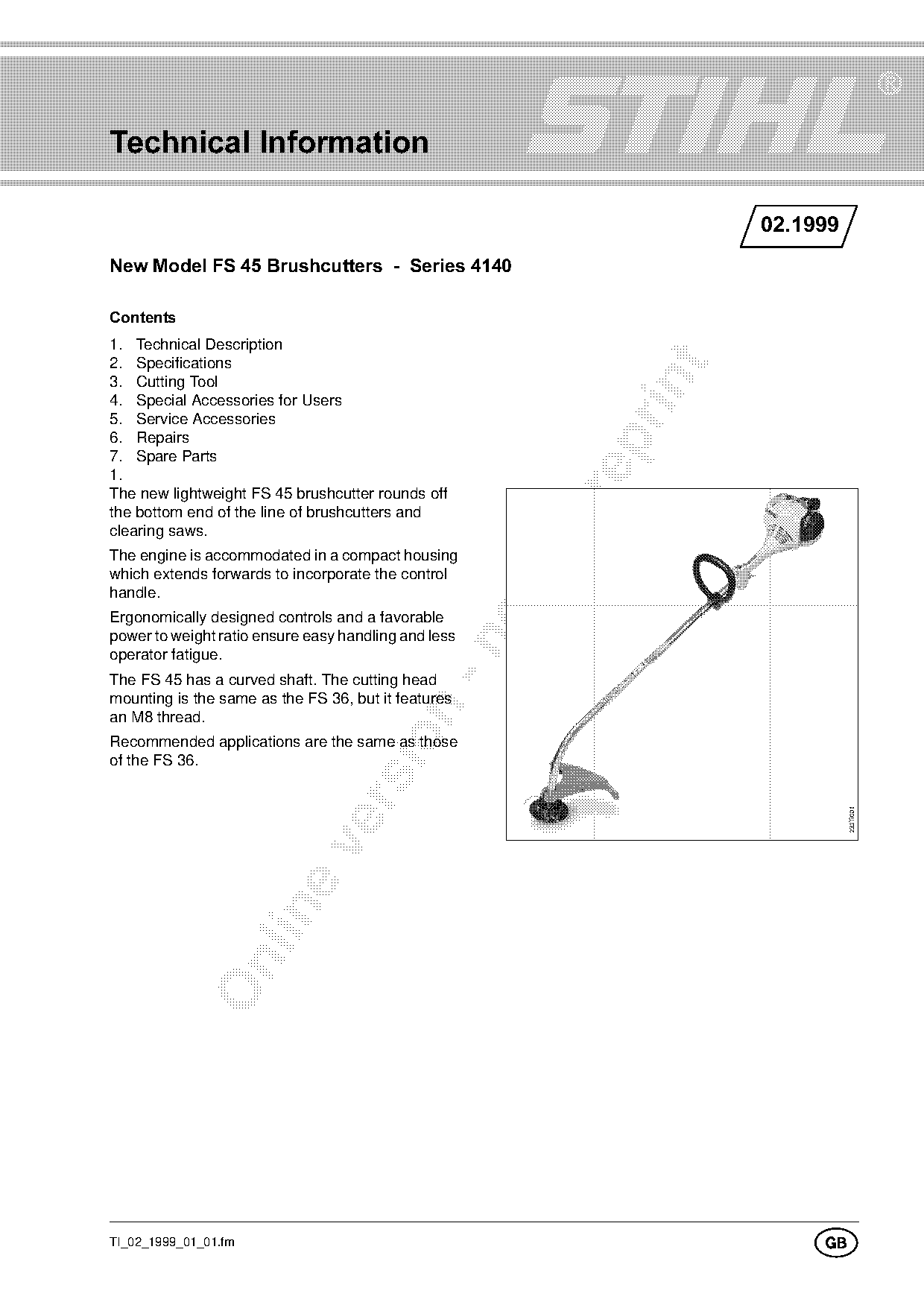
The new lightweight FS 45 brushcutter rounds off
the bottom end of the line of brushcutters and
clearing saws.
The engine is accommodated in a compact housing
which extends forwards to incorporate the control
handle.
Ergonomically designed controls and a favorable
power to weight ratio ensure easy handling and less

operator fatigue.
The FS 45 has a curved shaft. The cutting head
mounting is the same as the FS 36, but it features

an M8 thread.

Recommended applications are the same as those
of the FS 36.

TI_02_1999_01_01.fm
                                                                        *
Page 2 of 6
Text of page 2 — search, copy, screen readers
Page 2=====================================================================Technical Information  02.1

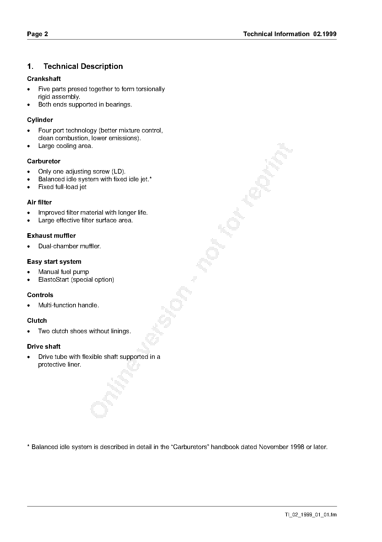
1.=====Technical Description
&UDQNVKDIW
.====cive parts presed together to form torsionally
     rigid assembly.
.====_oth=ends=supported=in=be~ringsK

&\OLQGHU
.====cour port technology (better mixture control,
     clean combustion, lower emissions).
.====i~rge cooling area.

&DUEXUHWRU
.====lnly one adjusting screw (LD).
.====_~lanced idle system with fixed idle jet.*

.====cixed full-load jet

Air filter

.====fmproved filter material with longer life.
.====i~rge effective filter surface area.

Exhaust muffler
.====aual-chamber muffler.

Easy start system

.====j~nual fuel pump
.====blastoStart (special option)

&RQWUROV


     Multi-function handle.

&OXWFK
.====qwo clutch shoes without linings.

Drive shaft

.====arive tube with flexible shaft supported in a
     protective liner.

* Balanced idle system is described in detail in the “Carburetors” handbook dated November 1998 or later.

                                                                                          TI_02_1999_01_01.fm
Page 3 of 6
Text of page 3 — search, copy, screen readers
Technical Information  02.1999=====================================================================Page 3

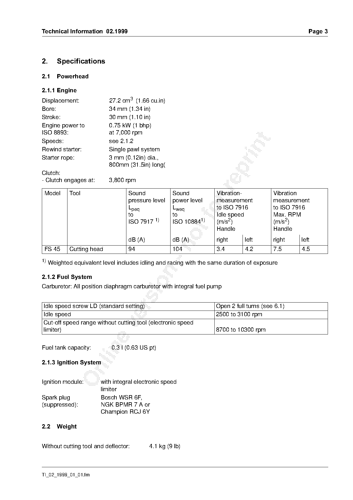
2.====Specifications

2.1===Powerhead

2.1.1=Engine
Displacement:             27.2 cm3 (1.66 cu.in)
Bore:                     34 mm (1.34 in)
Stroke:                   30 mm (1.10 in)
Engine power to           0.75 kW (1 bhp)
ISO 8893:                 at 7,000 rpm

Speeds:                   see 2.1.2

Rewind starter:           Single pawl system
Starter rope:             3 mm (0.12in) dia.,
                          800mm (31.5in) long(

Clutch:
- Clutch engages at:      3,800 rpm

Model      Tool                   Sound             Sound          Vibration-           Vibration
                                  pressure level    power level    measurement          measurement
                                  Lpeq
                                  to
                                                    Lweq
                                                    to
                                                             fo    to ISO 7916
                                                                   Idle speed
                                                                                        to ISO 7916
                                                                                        Max. RPM
                                  ISO 7917 1)       ISO 108841)    (m/s2)               (m/s2)
                                                                   Handle               Handle
                                  dB (A)            dB (A)         right     left       right   left

FS 45     Cutting head            94                104            3.4       4.2        7.5     4.5
1) Weighted equivalent level includes idling and racing with the same duration of exposure

2.1.2=Fuel System

Carburetor: All position diaphragm carburetor with integral fuel pump

Idle speed screw LD (standard setting)                            Open 2 full turns (see 6.1)

Idle speed                                                        2500 to 3100 rpm
Cut-off speed range without cutting tool (electronic speed

limiter)                                                          8700 to 10300 rpm

Fuel tank capacity:        0.3 l (0.63 US pt)

2.1.3=Ignition System

Ignition module:       with integral electronic speed
                       limiter
Spark plug             Bosch WSR 6F,
(suppressed):          NGK BPMR 7 A or
                       Champion RCJ 6Y

2.2===Weight

Without cutting tool and deflector:        4.1 kg (9 lb)

TI_02_1999_01_01.fm
Page 4 of 6
Text of page 4 — search, copy, screen readers
Page 4==========================================================================Technical Information  02.1

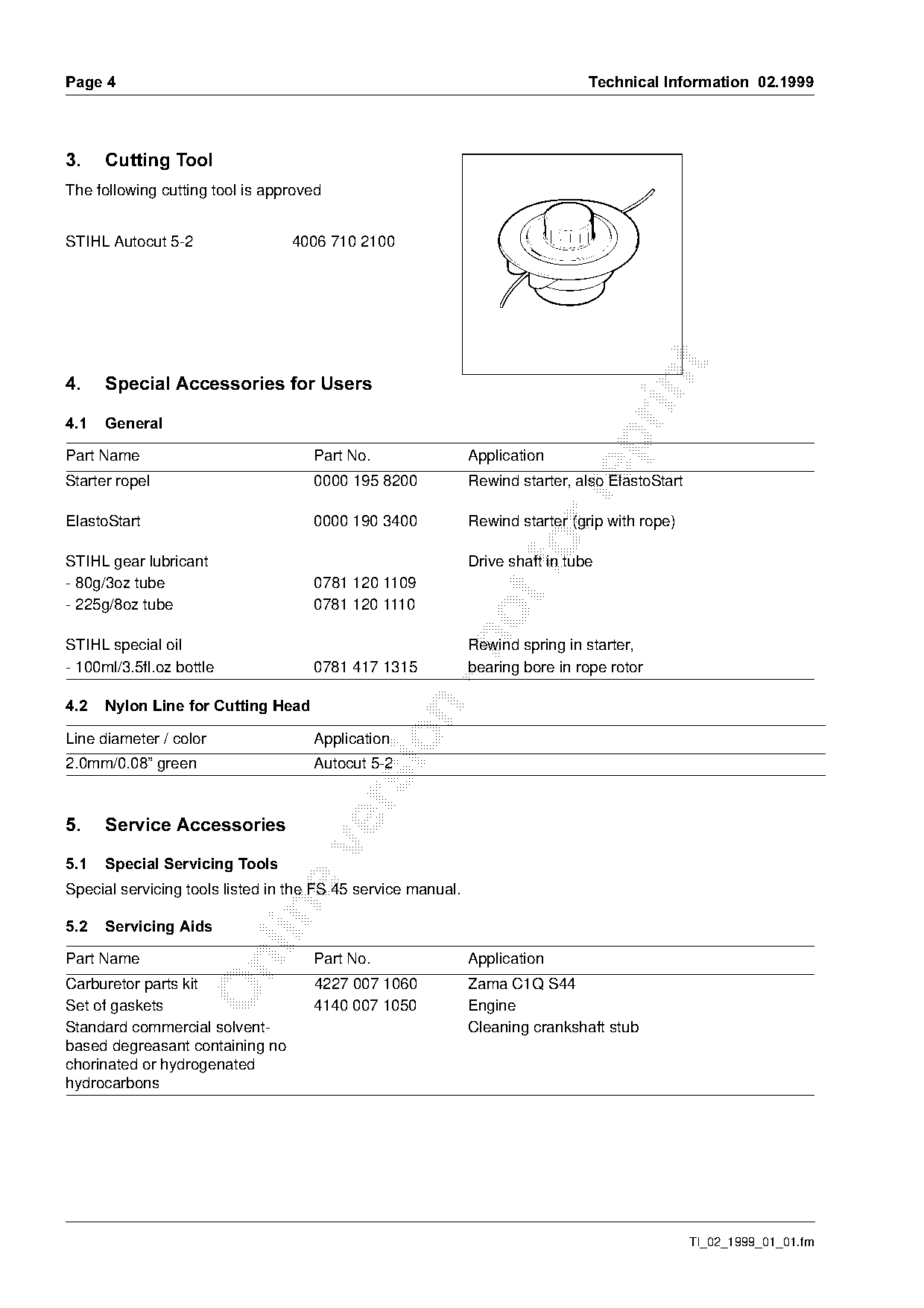
3.====Cutting Tool
The following cutting tool is approved

STIHL Autocut 5-2                4006 710 2100

4.====Special Accessories for Users

4.1===General

Part Name                            Part No.                 Application
Starter ropel                        0000 195 8200            Rewind starter, also ElastoStart

ElastoStart                          0000 190 3400            Rewind starter (grip with rope)

STIHL gear lubricant
                                                              Drive shaft in tube
- 80g/3oz tube                       0781 120 1109
- 225g/8oz tube                      0781 120 1110

STIHL special oil                                             Rewind spring in starter,
- 100ml/3.5fl.oz bottle              0781 417 1315            bearing bore in rope rotor

4.2===Nylon Line for Cutting Head

Line diameter / color                Application
2.0mm/0.08” green                    Autocut 5-2

5.====Service Accessories

5.1===Special Servicing Tools
Special servicing tools listed in the FS 45 service manual.

5.2===Servicing Aids

Part Name                            Part No.                 Application

Carburetor parts kit                 4227 007 1060            Zama C1Q S44
Set of gaskets                       4140 007 1050            Engine
Standard commercial solvent-                                  Cleaning crankshaft stub
based degreasant containing no
chorinated or hydrogenated
hydrocarbons

                                                                                                 TI_02_1999_01_01.fm
Page 5 of 6
Text of page 5 — search, copy, screen readers
Technical Information  02.1999=========================================================================Page 5

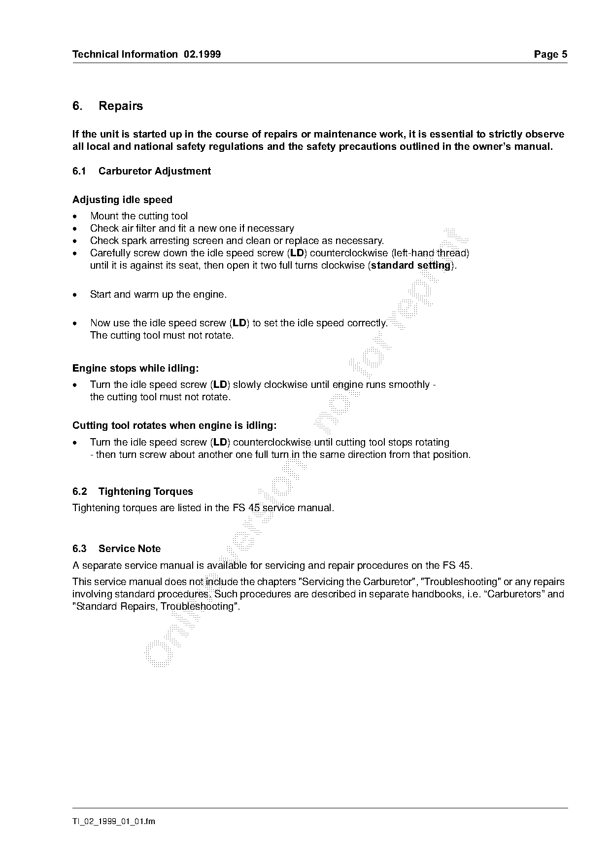
6.=====Repairs

If the unit is started up in the course of repairs or maintenance work, it is essential to strictly observe
all local and national safety regulations and the safety precautions outlined in the owner¶s manual.

6.1====Carburetor Adjustment

Adjusting idle speed
.=====jount the cutting tool
.=====`heck air filter and fit a new one if necessary
.=====`heck spark arresting screen and clean or replace as necessary.


      Carefully screw down the idle speed screw (/') counterclockwise (left-hand thread)
      until it is against its seat, then open it two full turns clockwise Estandard settingF.

.=====ptart and warm up the engine.

.=====kow use the idle speed screw (/') to set the idle speed correctly.

      The cutting tool must not rotate.

Engine stops while idling:=====================================fo
.=====qurn the idle speed screw (/') slowly clockwise until engine runs smoothly -
      the cutting tool must not rotate.

Cutting tool rotates when engine is idling
.=====qurn the idle speed screw (/') counterclockwise until cutting tool stops rotating
      - then turn screw about another one full turn in the same direction from that position.

6.2====Tightening Torques
Tightening torques are listed in the FS 45 service manual.

6.3====Service Note

A separate service manual is available for servicing and repair procedures on the FS 45.
This service manual does not include the chapters "Servicing the Carburetor", "Troubleshooting" or any repairs
involving standard procedures. Such procedures are described in separate handbooks, i.e. “Carburetors” and

"Standard Repairs, Troubleshooting".

TI_02_1999_01_01.fm
Page 6 of 6
Text of page 6 — search, copy, screen readers
Page 6=======================================================================Technical Information  02.1

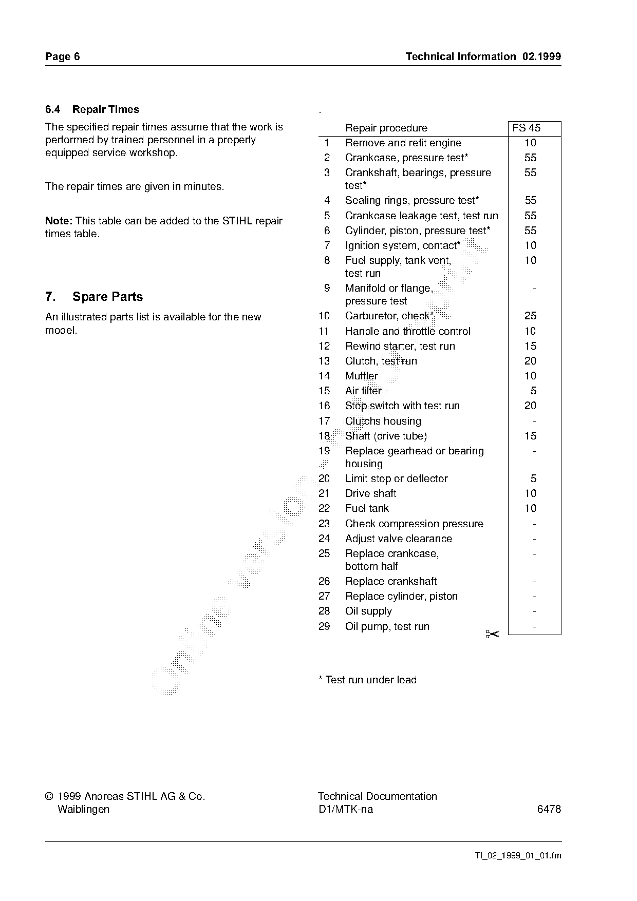
6.4===Repair Times=======================================.
The specified repair times assume that the work is               Repair procedure                   FS 45
performed by trained personnel in a properly                 1   Remove and refit engine              10
equipped service workshop.
                                                             2   Crankcase, pressure test*            55
                                                             3   Crankshaft, bearings, pressure       55
The repair times are given in minutes.                           test*
                                                             4   Sealing rings, pressure test*        55
                                                             5   Crankcase leakage test, test run     55
Note:=qhis table can be added to the STIHL repair
times table.                                                 6   Cylinder, piston, pressure test*     55
                                                             7   Ignition system, contact*            10

                                                             8   Fuel supply, tank vent,              10

                                                                 test run
                                                             9   Manifold or flange,                    -
7.====Spare Parts================================================pressure test

An illustrated parts list is available for the new       10      Carburetor, check*                   25
model.                                                   11      Handle and throttle control          10

                                                         12      Rewind starter, test run             15
                                                         13      Clutch, test run                     20
                                                         14
                                                         15
                                                                 Muffler
                                                                 Air filter
                                                                                                      10
                                                                                                       5
                                                         16      Stop switch with test run            20
                                                         17      Clutchs housing                       -
                                                         18      Shaft (drive tube)                   15

                                                         19      Replace gearhead or bearing           -
                                                                 housing
                                                         20      Limit stop or deflector               5

                                                         21      Drive shaft                          10

                                                         22      Fuel tank                            10
                                                         23      Check compression pressure            -
                                                         24      Adjust valve clearance                -

                                                         25      Replace crankcase,                    -
                                                                 bottom half
                                                         26      Replace crankshaft                     -

                                                         27      Replace cylinder, piston               -
                                                         28      Oil supply                             -

                                                         29      Oil pump, test run                     -
                                                                                              ✂

                                                         * Test run under load

© 1999 Andreas STIHL AG & Co.                            Technical Documentation
  Waiblingen                                             D1/MTK-na                                          6478

                                                                                            TI_02_1999_01_01.fm
Most of these PDFs embed fonts with a shifted character map, so the text above was recovered rather than copied — read it as a faithful but imperfect transcription, and treat the page image above each block as the authority where the two disagree — the figures exist only there, because they are vector drawings that text extraction cannot keep.