Technical Information · issue 5 of 1999
036 QS: Coasting brake
IssueTI 5/1999
Engine family 1125
Full text
Page 1 of 5
Text of page 1 — search, copy, screen readers
Technical Information

                                                                                                05.1999
036 QS Chainsaws - Series 1125

1.      Rear handle brake
        (separate system)

1.1     Method of Operation                             The STIHL Rear handle brake activating
The STIHL 036 QS chainsaw is equipped with an           mechanism is integrated in the throttle trigger
additional chain braking system.                        interlock (rear handle). The saw chain is
As before, the chain brake is activated by the mass     automatically locked in position when the rear
moment of inertia of the front hand guard in certain    handle is released (e.g. when carrying the running
situations if kickback is severe enough and can also    saw).
be activated manually by pushing the front hand         Warning!
guard forward in the direction of the bar nose. In
                                                        To help avoid personal injury or damage during
both these cases the movement of the saw chain is
                                                        cutting it is important to note the characteristics that
stopped within a fraction of a second.
                                                        make the STIHL 036 QS different from chainsaws
In addition to these functions, the new system brings   that do not have such a braking system. Before
the saw chain to a standstill in less than a second     operating the 036 QS for the first time, the user
after the operator lets go of the chainsaw’s rear       should make himself familiar with how the QS
handle. Similarly, the locked saw chain is not          system works. Special attention should be paid to
released until the operator presses down the throttle   the chapters "Chain Brake" and "Starting" in the
trigger interlock lever to operate the throttle.        owner’s manual.

The saw chain can be braked in three different
ways:
Quickstop
.     By the inertia of the front hand guard if the
      kickback force is high enough

.     Manually via the front hand guard

STIHL Rear handle brake
.     Manually via the rear handle - new function

TI_05_1999_30_02.fm
                                                                                                         U
Page 2 of 5
Text of page 2 — search, copy, screen readers
Page 2                                                                                  Technical Information 05.1999

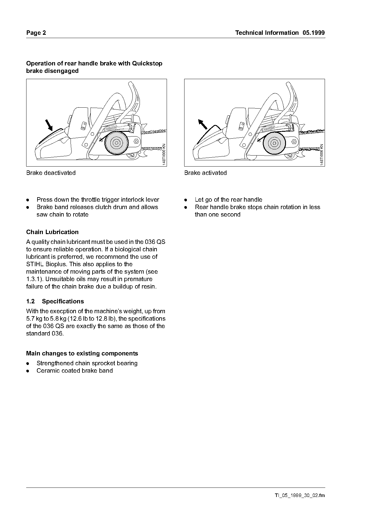
Operation of rear handle brake with Quickstop
brake disengaged

                                                        148TI000 KN

                                                                                                                        148TI006 KN
Brake deactivated                                                     Brake activated

.     Press down the throttle trigger interlock lever                 .   Let go of the rear handle
.     Brake band releases clutch drum and allows                      .   Rear handle brake stops chain rotation in less
      saw chain to rotate                                                 than one second

Chain Lubrication
A quality chain lubricant must be used in the 036 QS
to ensure reliable operation. If a biological chain
lubricant is preferred, we recommend the use of
STIHL Bioplus. This also applies to the
maintenance of moving parts of the system (see
1.3.1). Unsuitable oils may result in premature
failure of the chain brake due a buildup of resin.

1.2     Specifications
With the execption of the machine’s weight, up from
5.7 kg to 5.8 kg (12.6 lb to 12.8 lb), the specifications
of the 036 QS are exactly the same as those of the
standard 036.

Main changes to existing components
.     Strengthened chain sprocket bearing
.     Ceramic coated brake band

                                                                                                       TI_05_1999_30_02.fm
Page 3 of 5
Text of page 3 — search, copy, screen readers
Technical Information 05.1999                                                                         Page 3

1.3    Repairs
If the unit is started up in the course of repairs or
maintenance work it is essential to observe all local
safety regulations and the safety precautions
outlined in the owner’s manual.

1.3.1 Service Notes
Inspections, maintenance reopairs must be
performed by properly trained and authorized

                                                                                                            148TI007 KN
personnel.
Checking function of rear handle brake
(with bar and chain fitted)
.     Activate the throttle to wide open
.     Let go of the rear handle
.     The saw chain must come to a standstill in less
      than one second

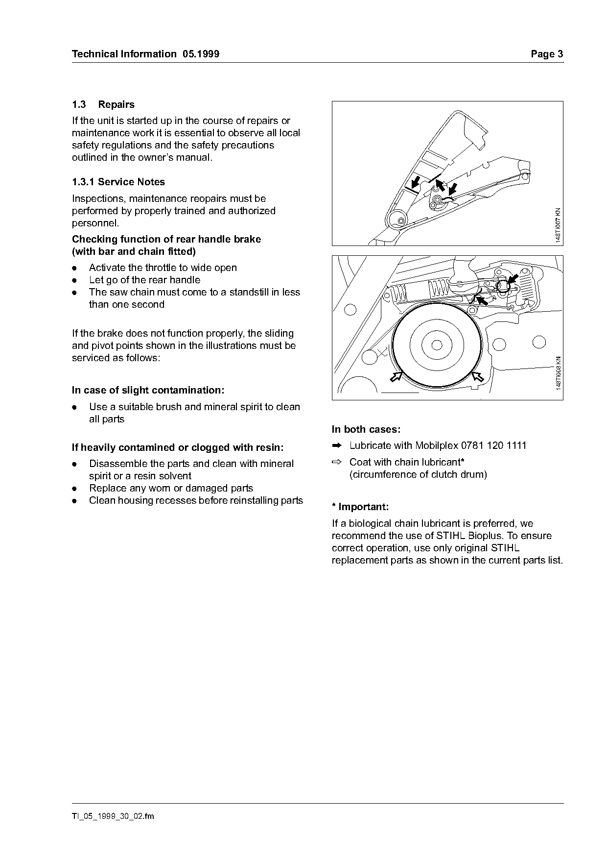
If the brake does not function properly, the sliding
and pivot points shown in the illustrations must be
serviced as follows:

                                                                                                            148TI008 KN
In case of slight contamination:
.     Use a suitable brush and mineral spirit to clean
      all parts
                                                         In both cases:
If heavily contamined or clogged with resin:             P Lubricate with Mobilplex 0781 120 1111
.     Disassemble the parts and clean with mineral       p Coat with chain lubricant*
      spirit or a resin solvent                            (circumference of clutch drum)
.     Replace any worn or damaged parts
.     Clean housing recesses before reinstalling parts
                                                         * Important:
                                                         If a biological chain lubricant is preferred, we
                                                         recommend the use of STIHL Bioplus. To ensure
                                                         correct operation, use only original STIHL
                                                         replacement parts as shown in the current parts list.

TI_05_1999_30_02.fm
Page 4 of 5
Text of page 4 — search, copy, screen readers
Page 4                                                                         Technical Information 05.1999

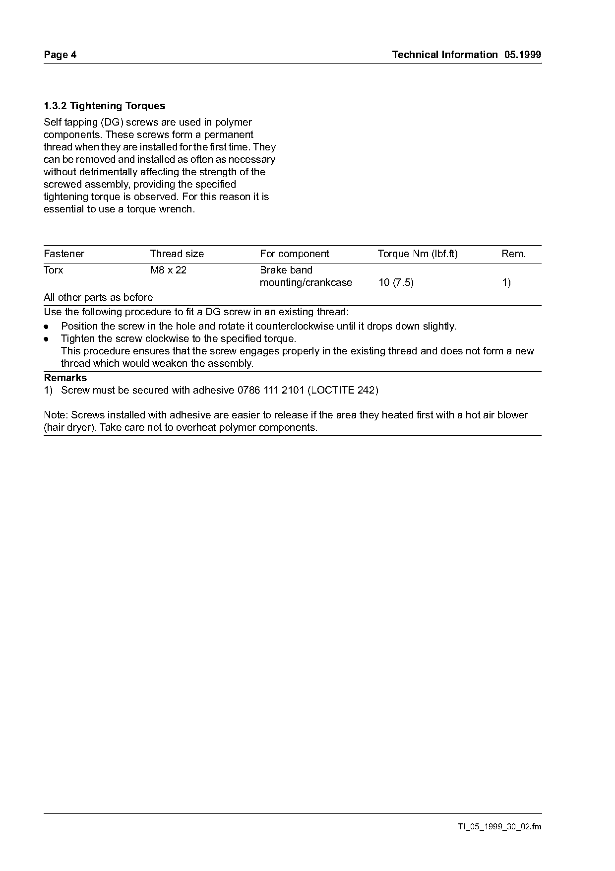
1.3.2 Tightening Torques
Self tapping (DG) screws are used in polymer
components. These screws form a permanent
thread when they are installed for the first time. They
can be removed and installed as often as necessary
without detrimentally affecting the strength of the
screwed assembly, providing the specified
tightening torque is observed. For this reason it is
essential to use a torque wrench.

Fastener                 Thread size               For component            Torque Nm (lbf.ft)            Rem.
Torx                     M8 x 22                   Brake band
                                                   mounting/crankcase      10 (7.5)                 1)
All other parts as before
Use the following procedure to fit a DG screw in an existing thread:
. Position the screw in the hole and rotate it counterclockwise until it drops down slightly.
. Tighten the screw clockwise to the specified torque.
     This procedure ensures that the screw engages properly in the existing thread and does not form a new
     thread which would weaken the assembly.
Remarks
1) Screw must be secured with adhesive 0786 111 2101 (LOCTITE 242)

Note: Screws installed with adhesive are easier to release if the area they heated first with a hot air blower
(hair dryer). Take care not to overheat polymer components.

                                                                                                 TI_05_1999_30_02.fm
Page 5 of 5
Text of page 5 — search, copy, screen readers
Technical Information 05.1999                                                                          Page 5

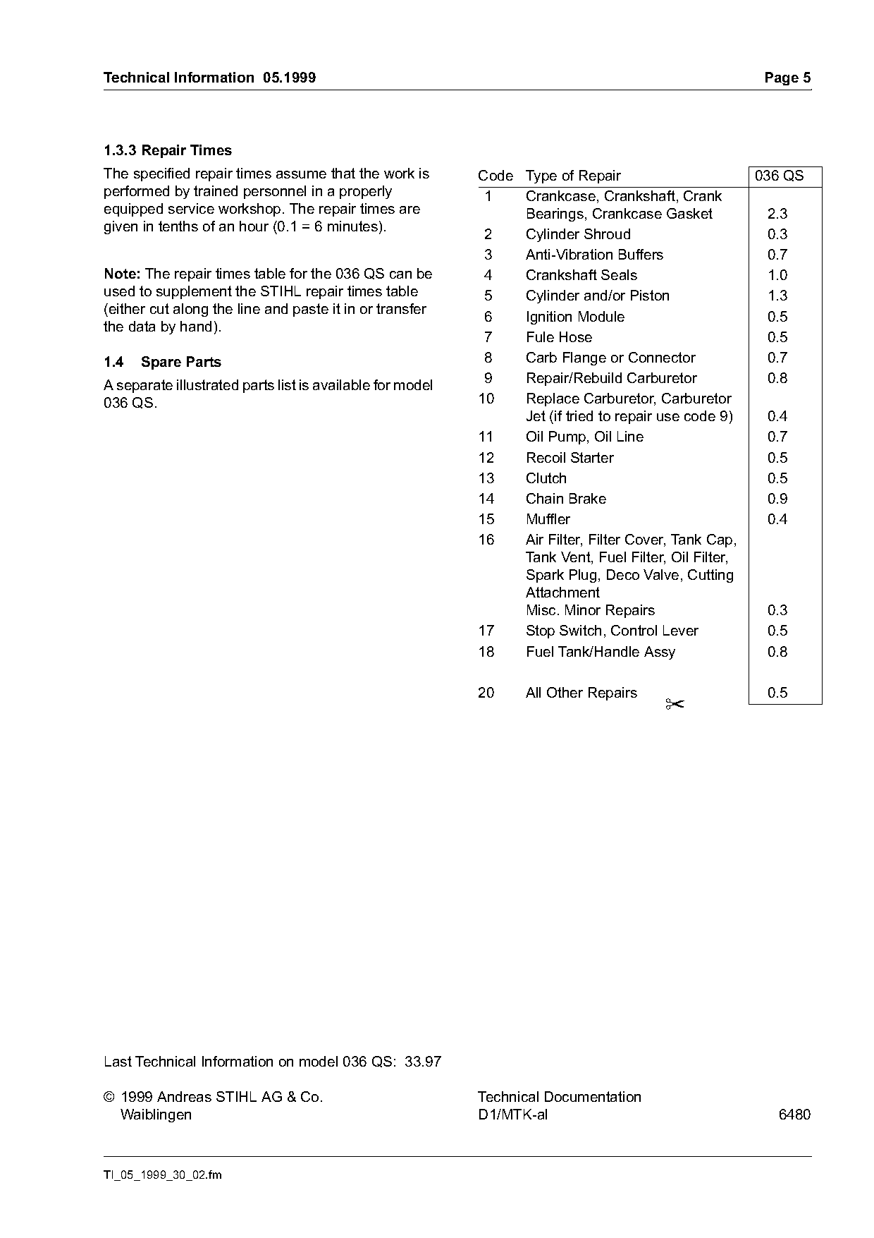
1.3.3 Repair Times
The specified repair times assume that the work is         Code Type of Repair                        036 QS
performed by trained personnel in a properly                1   Crankcase, Crankshaft, Crank
equipped service workshop. The repair times are                 Bearings, Crankcase Gasket             2.3
given in tenths of an hour (0.1 = 6 minutes).
                                                            2   Cylinder Shroud                        0.3
                                                            3   Anti-Vibration Buffers                 0.7
Note: The repair times table for the 036 QS can be          4   Crankshaft Seals                       1.0
used to supplement the STIHL repair times table             5   Cylinder and/or Piston                 1.3
(either cut along the line and paste it in or transfer
                                                            6   Ignition Module                        0.5
the data by hand).
                                                            7   Fule Hose                              0.5
1.4   Spare Parts                                           8   Carb Flange or Connector               0.7
A separate illustrated parts list is available for model    9   Repair/Rebuild Carburetor              0.8
036 QS.                                                    10   Replace Carburetor, Carburetor
                                                                Jet (if tried to repair use code 9)    0.4
                                                           11   Oil Pump, Oil Line                     0.7
                                                           12   Recoil Starter                         0.5
                                                           13   Clutch                                 0.5
                                                           14   Chain Brake                            0.9
                                                           15   Muffler                                0.4
                                                           16   Air Filter, Filter Cover, Tank Cap,
                                                                Tank Vent, Fuel Filter, Oil Filter,
                                                                Spark Plug, Deco Valve, Cutting
                                                                Attachment
                                                                Misc. Minor Repairs                    0.3
                                                           17   Stop Switch, Control Lever             0.5
                                                           18   Fuel Tank/Handle Assy                  0.8

                                                           20     All Other Repairs                    0.5
                                                                                       ✂

Last Technical Information on model 036 QS: 33.97

© 1999 Andreas STIHL AG & Co.                              Technical Documentation
  Waiblingen                                               D1/MTK-al                                    6480

TI_05_1999_30_02.fm
Most of these PDFs embed fonts with a shifted character map, so the text above was recovered rather than copied — read it as a faithful but imperfect transcription, and treat the page image above each block as the authority where the two disagree — the figures exist only there, because they are vector drawings that text extraction cannot keep.