Technical Information · issue 14 of 1999
HT 75, Servicing: Telescopic shaft; Cutting attach
IssueTI 14/1999
Full text
Page 1 of 6
Text of page 1 — search, copy, screen readers
Technical Information

                                                                                                                            14.1999
Servicing Model HT 75 Pole Pruners - Series 4138

This Technical Information bulletin supersedes and replaces TI 03.97.
Inspection and servicing work must be performed by properly trained and authorized personnel.

Contents
1. Telescopic tube
2. Cutting attachment
3. Lubrication

Note: Refer to the illustrated parts               -   Remove the plastic liner and
list for better orientation during the                 retaining ring.
following operations.

1.      Telescopic tube

                                                                                                                                            390RA003 KN
1.1     Drive shaft
                                                                                                                        4
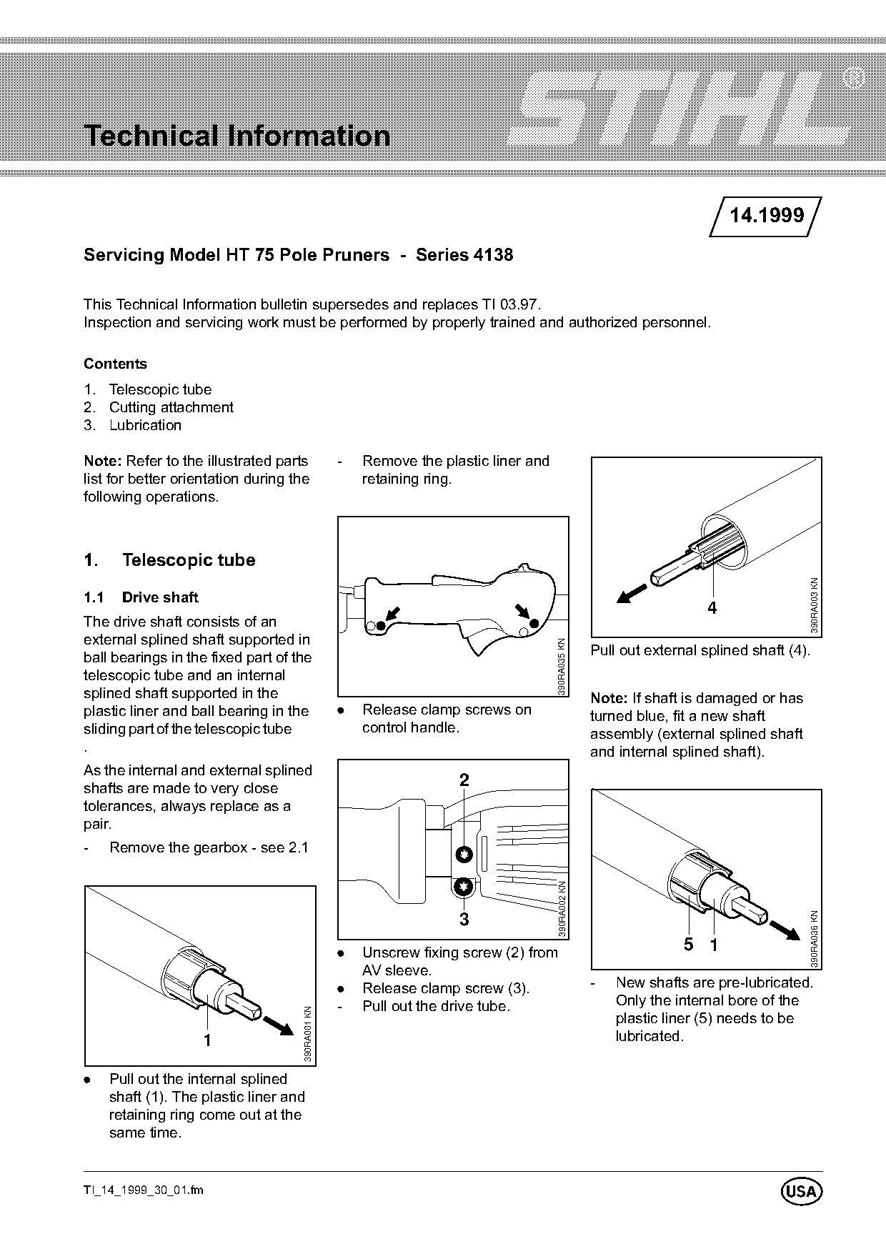
The drive shaft consists of an
external splined shaft supported in
                                                                                      390RA035 KN

ball bearings in the fixed part of the                                                               Pull out external splined shaft (4).
telescopic tube and an internal
splined shaft supported in the                                                                       Note: If shaft is damaged or has
plastic liner and ball bearing in the              .   Release clamp screws on                       turned blue, fit a new shaft
sliding part of the telescopic tube                    control handle.                               assembly (external splined shaft
.                                                                                                    and internal splined shaft).
As the internal and external splined
shafts are made to very close                                        2
tolerances, always replace as a
pair.
-     Remove the gearbox - see 2.1
                                                                                       390RA002 KN

                                                                                                                                        390RA036 KN

                                                                     3
                                                   .   Unscrew fixing screw (2) from                                5 1
                                                       AV sleeve.
                                                   .   Release clamp screw (3).                      -   New shafts are pre-lubricated.
                                                   -   Pull out the drive tube.                          Only the internal bore of the
                                     390RA001 KN

                                                                                                         plastic liner (5) needs to be
                      1                                                                                  lubricated.

.     Pull out the internal splined
      shaft (1). The plastic liner and
      retaining ring come out at the
      same time.

TI_14_1999_30_01.fm
                                                                                                                                   U
Page 2 of 6
Text of page 2 — search, copy, screen readers
Page 2                                                                                                   Technical Information 14.1999

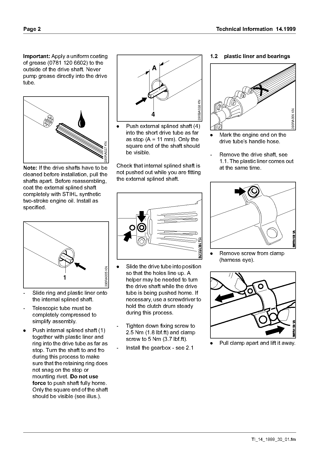
Important: Apply a uniform coating                                                                   1.2     plastic liner and bearings
of grease (0781 120 6602) to the
outside of the drive shaft. Never                                 A
pump grease directly into the drive
tube.

                                                                                       390BA038 KN

                                                                                                                                           390RA006 KN
                                                                  4
                                                   .   Push external splined shaft (4)
                                                       into the short drive tube as far              .     Mark the engine end on the
                                                       as stop (A = 11 mm). Only the                       drive tube’s handle hose.
                                    390RA037 KN

                                                       square end of the shaft should
                                                       be visible.                                   -     Remove the drive shaft, see
                                                                                                           1.1. The plastic liner comes out
Note: If the drive shafts have to be               Check that internal splined shaft is                    at the same time.
cleaned before installation, pull the              not pushed out while you are fitting
shafts apart. Before reassembling,                 the external splined shaft.
coat the external splined shaft
completely with STIHL synthetic
two-stroke engine oil. Install as
specified.

                                                                                                     .     Remove screw from clamp
                                                                                                           (harness eye).
                                                   .   Slide the drive tube into position
                                     390RA005 KN

                                                       so that the holes line up. A
                 1                                     helper may be needed to turn
                                                       the drive shaft while the drive
-   Slide ring and plastic liner onto                  tube is being pushed home. If
    the internal splined shaft.                        necessary, use a screwdriver to
-   Telescopic tube must be                            hold the clutch drum steady
    completely compressed to                           during this process.
    simplify assembly.
                                                   -   Tighten down fixing screw to
.   Push internal splined shaft (1)                    2.5 Nm (1.8 lbf.ft) and clamp
    together with plastic liner and                    screw to 5 Nm (3.7 lbf.ft).
    ring into the drive tube as far as                                                               .     Pull clamp apart and lift it away.
    stop. Turn the shaft to and fro                -   Install the gearbox - see 2.1
    during this process to make
    sure that the retaining ring does
    not snag on the stop or
    mounting rivet. Do not use
    force to push shaft fully home.
    Only the square end of the shaft
    should be visible (see illus.).

                                                                                                                         TI_14_1999_30_01.fm
Page 3 of 6
Text of page 3 — search, copy, screen readers
Technical Information 14.1999                                                                                                               Page 3

            4
                     1                                                       12
                                                                                                                                  A B
                                                                                                                  11
                                                                                                                                      B

                                                                                               390RA042 KN

                                                                                                                                                   390RA045 KN
                                           390RA039 KN
        3
                                                                                  13
                             2
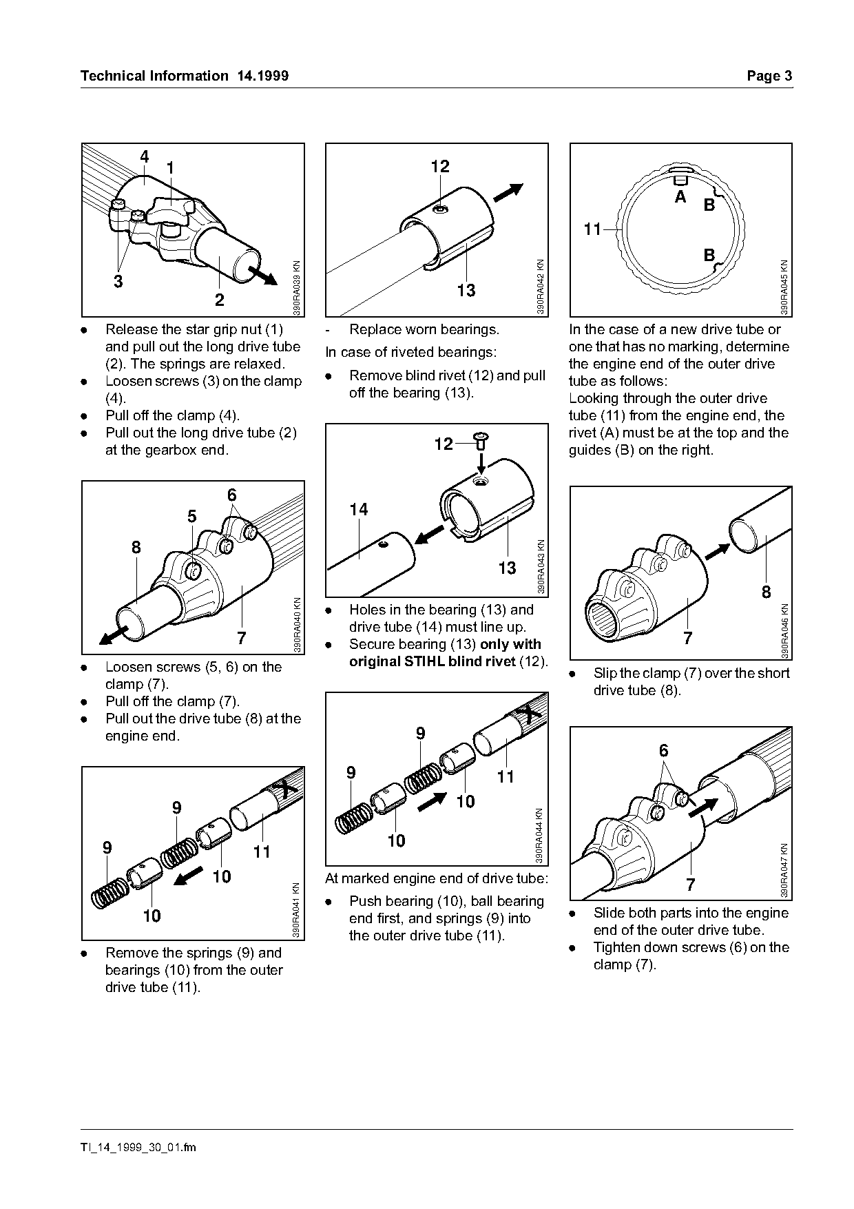
.   Release the star grip nut (1)                         -   Replace worn bearings.                          In the case of a new drive tube or
    and pull out the long drive tube                      In case of riveted bearings:                        one that has no marking, determine
    (2). The springs are relaxed.                                                                             the engine end of the outer drive
.   Loosen screws (3) on the clamp                        .   Remove blind rivet (12) and pull                tube as follows:
    (4).                                                      off the bearing (13).                           Looking through the outer drive
.   Pull off the clamp (4).                                                                                   tube (11) from the engine end, the
.   Pull out the long drive tube (2)                                                                          rivet (A) must be at the top and the
    at the gearbox end.                                                      12                               guides (B) on the right.

                                 6
                         5                                    14
                                                                                                390RA043 KN
            8
                                                                                         13
                                                                                                                                               8
                                            390RA040 KN

                                                          .   Holes in the bearing (13) and

                                                                                                                                                    390RA046 KN
                                                              drive tube (14) must line up.
                                  7                       .   Secure bearing (13) only with                                       7
.   Loosen screws (5, 6) on the                               original STIHL blind rivet (12).
                                                                                                              .    Slip the clamp (7) over the short
    clamp (7).                                                                                                     drive tube (8).
.   Pull off the clamp (7).
.   Pull out the drive tube (8) at the
    engine end.                                                          9
                                                                                                                              6
                                                              9                        11
                     9                                                            10
                                                                                              390RA044 KN

    9                                                               10
                                                                                                                                                   390RA047 KN

                                      11
                             10                           At marked engine end of drive tube:
                                                                                                                                  7
                                           390RA041 KN

                                                          .   Push bearing (10), ball bearing
                10                                            end first, and springs (9) into                 .    Slide both parts into the engine
                                                              the outer drive tube (11).                           end of the outer drive tube.
.   Remove the springs (9) and                                                                                .    Tighten down screws (6) on the
    bearings (10) from the outer                                                                                   clamp (7).
    drive tube (11).

TI_14_1999_30_01.fm
Page 4 of 6
Text of page 4 — search, copy, screen readers
Page 4                                                                                                     Technical Information 14.1999

                                                   2.      Cutting attachment
                     5                             2.1     Gearbox
          8                                        For versions with friction clutch,                                                    6
                                                   also refer to service notes in
                                                   TI 36.98.

                                     390RA048 KN

                                                                                                                                             390RA016 KN
                                                                                                                      5
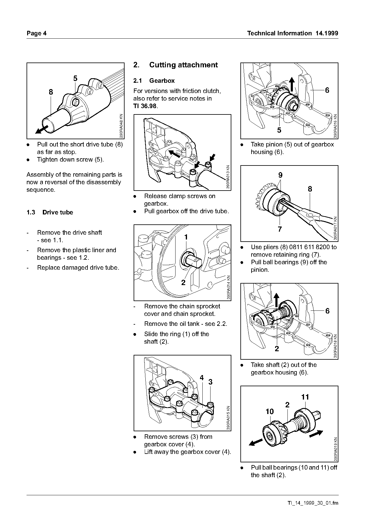
.     Pull out the short drive tube (8)                                                                .    Take pinion (5) out of gearbox
      as far as stop.                                                                                       housing (6).
.     Tighten down screw (5).

                                                                                        390RA013 KN
Assembly of the remaining parts is                                                                                    9
now a reversal of the disassembly
sequence.                                                                                                                         8
                                                   .     Release clamp screws on
                                                         gearbox.
1.3     Drive tube                                 .     Pull gearbox off the drive tube.

                                                                                                                                             390RA017 KN
-     Remove the drive shaft                                                                                          7
      - see 1.1.                                                        1
-     Remove the plastic liner and                                                                     .    Use pliers (8) 0811 611 8200 to
      bearings - see 1.2.                                                                                   remove retaining ring (7).
                                                                                                       .    Pull ball bearings (9) off the
-     Replace damaged drive tube.                                                                           pinion.
                                                                                         390RA014 KN


                                                   -     Remove the chain sprocket
                                                         cover and chain sprocket.                                                       6
                                                   -     Remove the oil tank - see 2.2.
                                                   .     Slide the ring (1) off the                                                          390RA018 KN
                                                         shaft (2).
                                                                                                                      2

                                                                                                       .    Take shaft (2) out of the
                                                                                                            gearbox housing (6).
                                                                               4
                                                                                   3

                                                                                                                               11
                                                                                                                          2
                                                                                        390RA015 KN


                                                   .     Remove screws (3) from
                                                                                                                                             390RA019 KN

                                                         gearbox cover (4).
                                                   .     Lift away the gearbox cover (4).

                                                                                                       .    Pull ball bearings (10 and 11) off
                                                                                                            the shaft (2).

                                                                                                                          TI_14_1999_30_01.fm
Page 5 of 6
Text of page 5 — search, copy, screen readers
Technical Information 14.1999                                                                                                           Page 5

                             11
                                                                                 5
              2                                                                                                                    1
    10
                                                                                      6

                                                                                           390RA023 KN

                                                                                                                                              390RA026 KN
                                      390RA020 KN
                                                                                                                           2

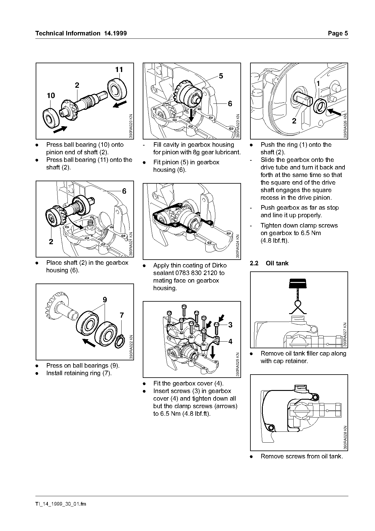
.   Press ball bearing (10) onto                    -   Fill cavity in gearbox housing                   .     Push the ring (1) onto the
    pinion end of shaft (2).                            for pinion with 8g gear lubricant.                     shaft (2).
.   Press ball bearing (11) onto the                .   Fit pinion (5) in gearbox                        -     Slide the gearbox onto the
    shaft (2).                                          housing (6).                                           drive tube and turn it back and
                                                                                                               forth at the same time so that
                                                                                                               the square end of the drive
                                  6                                                                            shaft engages the square
                                                                                                               recess in the drive pinion.
                                                                                                         -     Push gearbox as far as stop
                                                                                                               and line it up properly.
                                                                                                         -     Tighten down clamp screws
                                                                                                               on gearbox to 6.5 Nm
                                      390RA021 KN

                                                                                          390RA024 KN
     2                                                                                                         (4.8 lbf.ft).

.   Place shaft (2) in the gearbox                  .   Apply thin coating of Dirko                      2.2    Oil tank
    housing (6).                                        sealant 0783 830 2120 to
                                                        mating face on gearbox
                                                        housing.
                         9

                                  7
                                                                                      3

                                                                                                                                              390RA027 KN
                                      390RA022 KN

                                                                                      4
                                                                                                         .     Remove oil tank filler cap along
                                                                                          390RA025 KN

                                                                                                               with cap retainer.
.   Press on ball bearings (9).
.   Install retaining ring (7).
                                                    .   Fit the gearbox cover (4).
                                                    .   Insert screws (3) in gearbox
                                                        cover (4) and tighten down all
                                                        but the clamp screws (arrows)
                                                        to 6.5 Nm (4.8 lbf.ft).
                                                                                                                                              390RA028 KN

                                                                                                         .     Remove screws from oil tank.

TI_14_1999_30_01.fm
Page 6 of 6
Text of page 6 — search, copy, screen readers
Page 6                                                                                                         Technical Information 14.1999

                                                                                                          3.     Lubrication
                                                                                                          Further testing has resulted in a
                                                                                                          change in the use of lubricants.
                                                                                                          The following lubricants should be
                                                                                                          used:

                                                                                                          3.1    Gearbox

                                                                                            390RA032 KN
                                           390RA029 KN

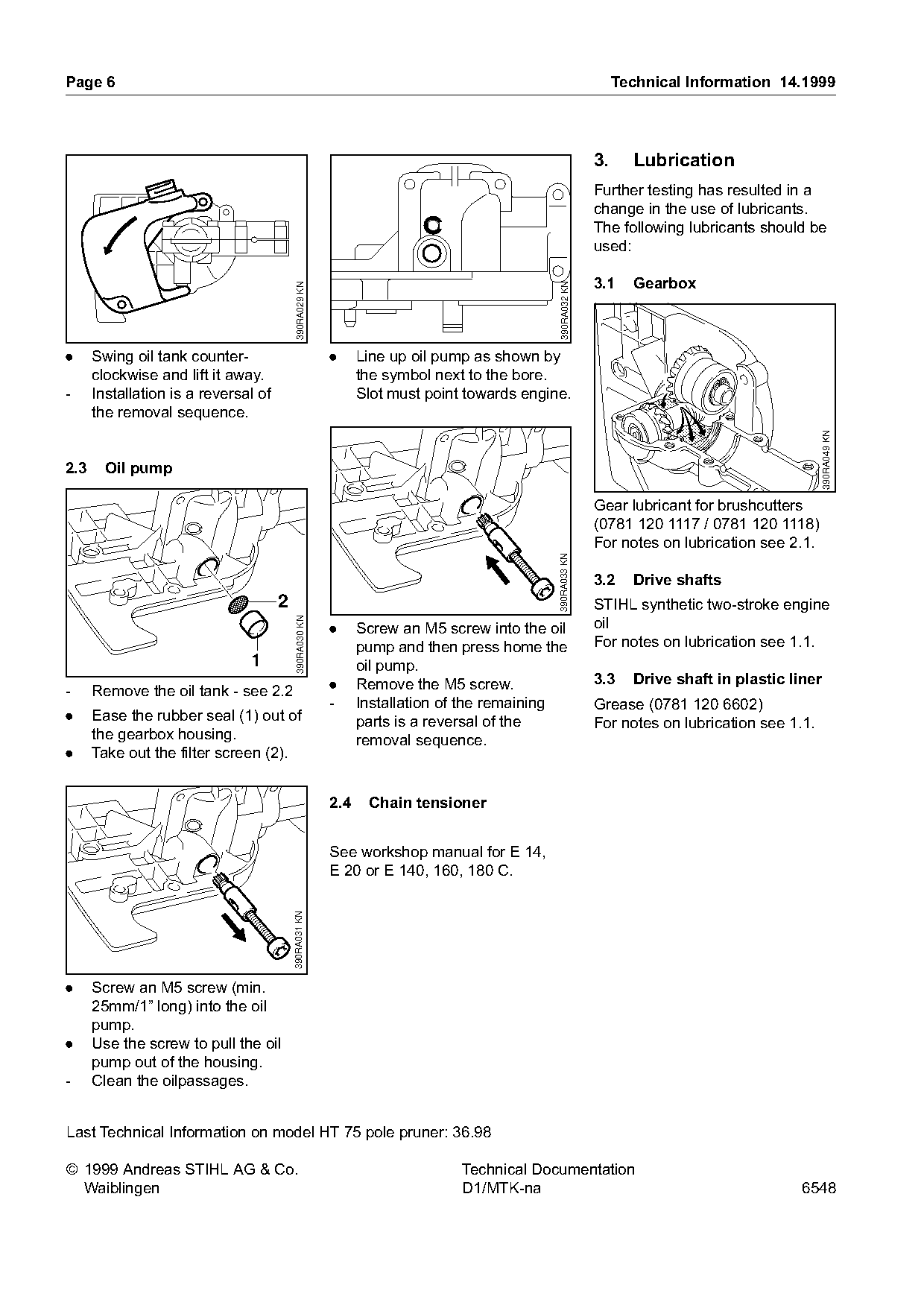
.     Swing oil tank counter-                            .     Line up oil pump as shown by
      clockwise and lift it away.                              the symbol next to the bore.
-     Installation is a reversal of                            Slot must point towards engine.
      the removal sequence.

                                                                                                                                                390RA049 KN
2.3     Oil pump

                                                                                                          Gear lubricant for brushcutters
                                                                                                          (0781 120 1117 / 0781 120 1118)
                                                                                                          For notes on lubrication see 2.1.
                                                                                            390RA033 KN
                                                                                                          3.2    Drive shafts
                                      2                                                                   STIHL synthetic two-stroke engine
                                                                                                          oil
                                           390RA030 KN

                                                         .     Screw an M5 screw into the oil
                                                               pump and then press home the               For notes on lubrication see 1.1.
                               1                               oil pump.
                                                         .     Remove the M5 screw.                       3.3    Drive shaft in plastic liner
-     Remove the oil tank - see 2.2
                                                         -     Installation of the remaining              Grease (0781 120 6602)
.     Ease the rubber seal (1) out of                          parts is a reversal of the                 For notes on lubrication see 1.1.
      the gearbox housing.                                     removal sequence.
.     Take out the filter screen (2).

                                                         2.4    Chain tensioner

                                                         See workshop manual for E 14,
                                                         E 20 or E 140, 160, 180 C.
                                          390RA031 KN

.     Screw an M5 screw (min.
      25mm/1” long) into the oil
      pump.
.     Use the screw to pull the oil
      pump out of the housing.
-     Clean the oilpassages.

Last Technical Information on model HT 75 pole pruner: 36.98

© 1999 Andreas STIHL AG & Co.                                                 Technical Documentation
  Waiblingen                                                                  D1/MTK-na                                                   6548
Most of these PDFs embed fonts with a shifted character map, so the text above was recovered rather than copied — read it as a faithful but imperfect transcription, and treat the page image above each block as the authority where the two disagree — the figures exist only there, because they are vector drawings that text extraction cannot keep.