Technical Information · issue 21 of 1999
FC 75, FH 75, HL 75, 75 K, HT 70, 75, FS 75, 80, 85, FR 85: Uprated Engine
IssueTI 21/1999
Full text
Page 1 of 8
Text of page 1 — search, copy, screen readers
Technical Information

                                                                                                         21.1999
STIHL FH 75                           Power Scythe                                    - Series 4230
STIHL HL 75, 75 K                     Hedge Trimmers                                  - Series 4230
STIHL HT 70, 75                       Pole Pruners                                    - Series 4138
STIHL FC 75                           Power Edger                                     - Series 4137
STIHL FS 75, 80, 85                   Brushcutters                                    - Series 4137

Contents
1. Uprated Engine
   1.1 Filter housing
   1.2 Carburetor
   1.3 Spacer flange
   1.4 Shroud
   1.5 Service notes
   1.6 Summary

1.    Uprated Engine
                                                                   Refer to “1.5 Service notes” when replacing parts
                                                                   and assemblies.
             4

                                                                   1.1   Filter housing
                                          2
                                                                                 5                      5
                              1

                             3
                                                                                                                       392TI021 KN
                                                     392TI000 KN

                                                                                      2                       2

                                                                   Left: Previous version
                                                                   Right: New version
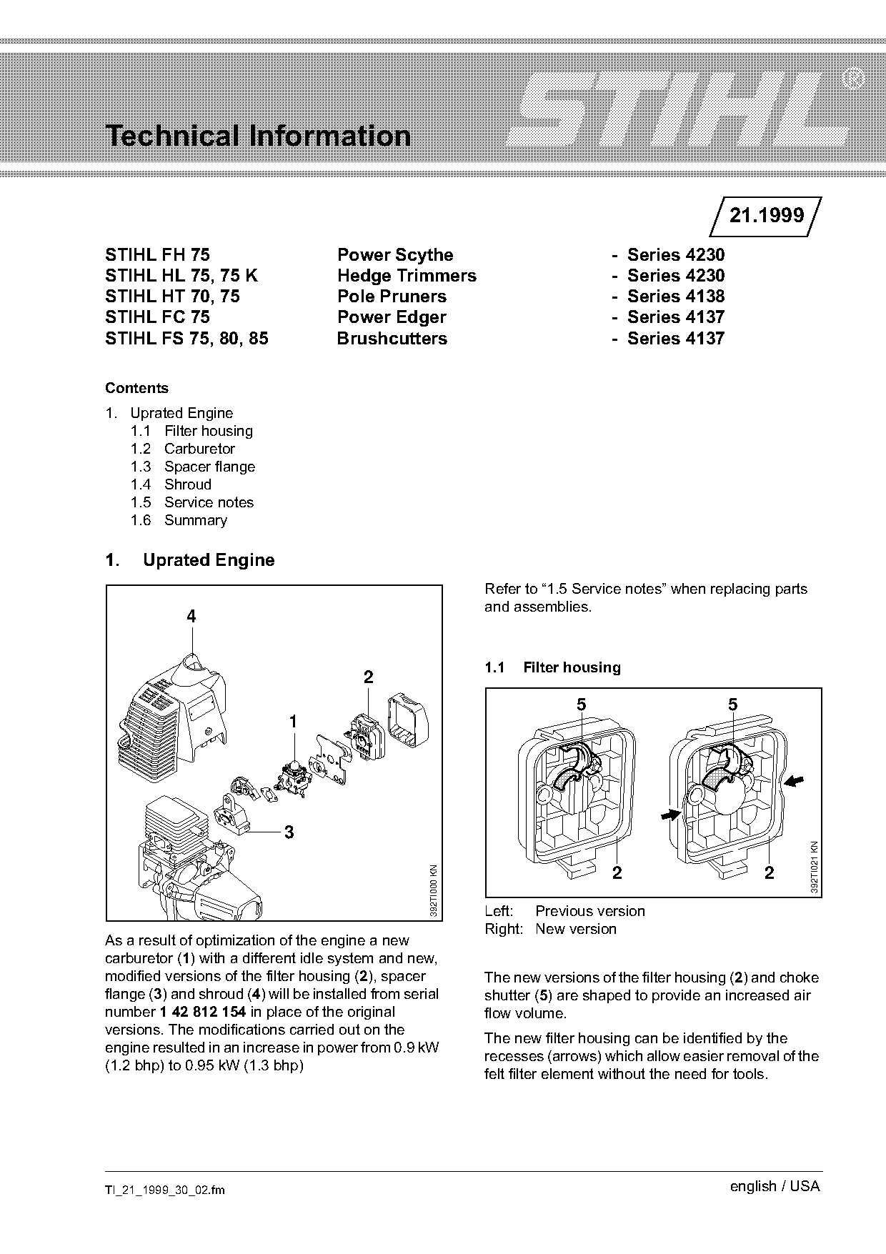
As a result of optimization of the engine a new
carburetor (1) with a different idle system and new,
modified versions of the filter housing (2), spacer                The new versions of the filter housing (2) and choke
flange (3) and shroud (4) will be installed from serial            shutter (5) are shaped to provide an increased air
number 1 42 812 154 in place of the original                       flow volume.
versions. The modifications carried out on the
                                                                   The new filter housing can be identified by the
engine resulted in an increase in power from 0.9 kW
                                                                   recesses (arrows) which allow easier removal of the
(1.2 bhp) to 0.95 kW (1.3 bhp)
                                                                   felt filter element without the need for tools.

TI_21_1999_30_02.fm                                                                                      english / USA
Page 2 of 8
Text of page 2 — search, copy, screen readers
Page 2                                                                                 Technical Information 21.1999

The new choke shutter (5) has a smoother surface                   Outlet valve (new)
structure and is wider than the previous version.

1.2   Carburetor                                                                A                          B            C

                                                                                                                            392TI023 KN
            L                       LD                             Left: C1Q-S41 previous version
                                                                   Right: C1Q-S45 new version
                                                                   A = Valve jet with integral fixed jet
                                                                   B = Outlet valve
                                                     392TI022 KN

          LA                                                       C = Fixed jet

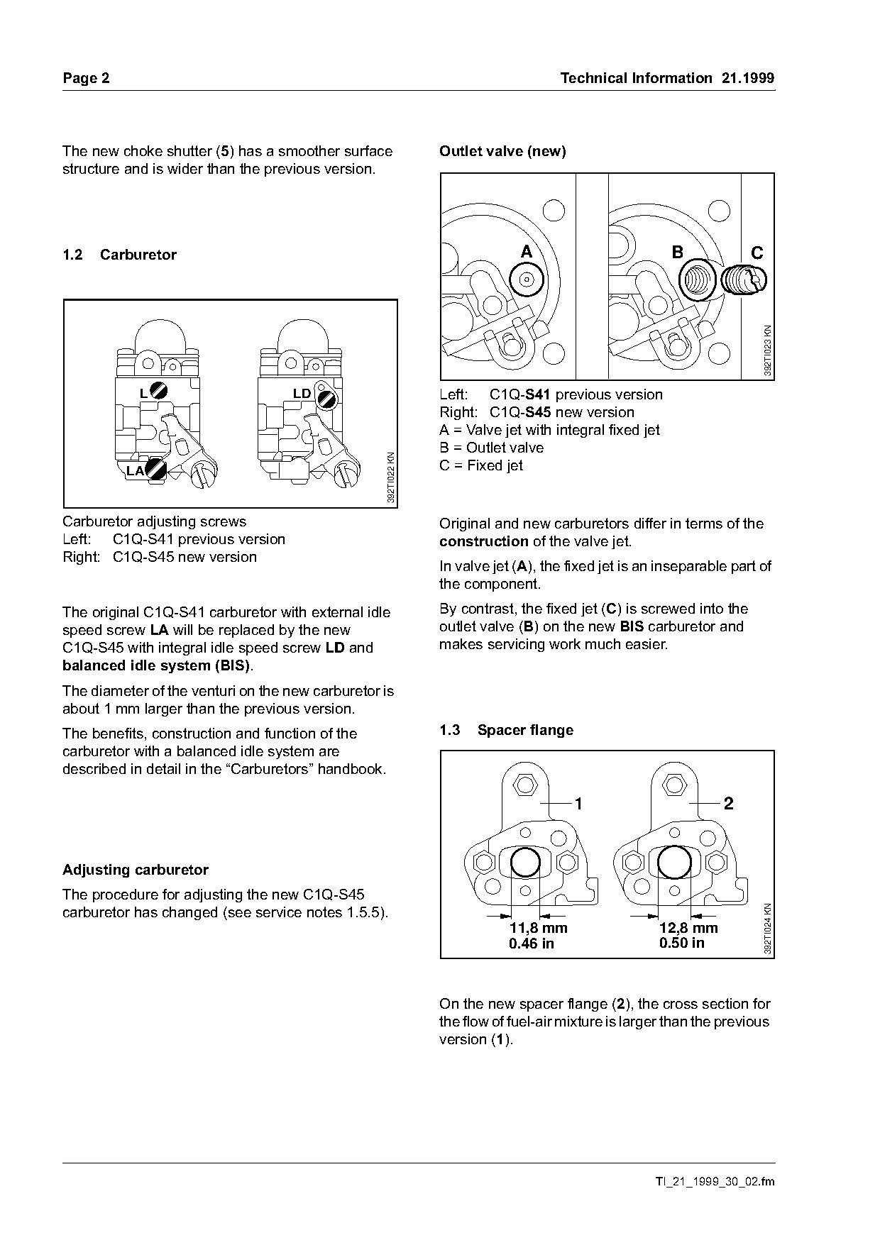
Carburetor adjusting screws                                        Original and new carburetors differ in terms of the
Left: C1Q-S41 previous version                                     construction of the valve jet.
Right: C1Q-S45 new version
                                                                   In valve jet (A), the fixed jet is an inseparable part of
                                                                   the component.
The original C1Q-S41 carburetor with external idle                 By contrast, the fixed jet (C) is screwed into the
speed screw LA will be replaced by the new                         outlet valve (B) on the new BIS carburetor and
C1Q-S45 with integral idle speed screw LD and                      makes servicing work much easier.
balanced idle system (BIS).
The diameter of the venturi on the new carburetor is
about 1 mm larger than the previous version.
The benefits, construction and function of the                     1.3   Spacer flange
carburetor with a balanced idle system are
described in detail in the “Carburetors” handbook.

                                                                                          1                        2

Adjusting carburetor
The procedure for adjusting the new C1Q-S45
                                                                                                                            392TI024 KN

carburetor has changed (see service notes 1.5.5).
                                                                              11,8 mm                   12,8 mm
                                                                              0.46 in                   0.50 in

                                                                   On the new spacer flange (2), the cross section for
                                                                   the flow of fuel-air mixture is larger than the previous
                                                                   version (1).

                                                                                                        TI_21_1999_30_02.fm
Page 3 of 8
Text of page 3 — search, copy, screen readers
Technical Information 21.1999                                                                                   Page 3

1.4   Shroud                                                     1.5   Service notes

                                                                 1.5.1 Original machine versions
                                                                 If either the filter housing, carburetor or spacer
                                                                 flange have to be replaced as separate parts, the
                                                                 replacement parts must be the original versions.

       L                       L                                 The new shroud can be installed on both previous
                                  LD
      LA                        LA                               and new versions.

                                                   392TI025 KN
                                                                 1.5.2 Earlier machine versions
Setting symbols                                                  In addition to the above notes (1.5.1), it is essential
Left: Original shroud                                            to observe the service notes given in TI 41.97 under
Right: New shroud                                                1.3.
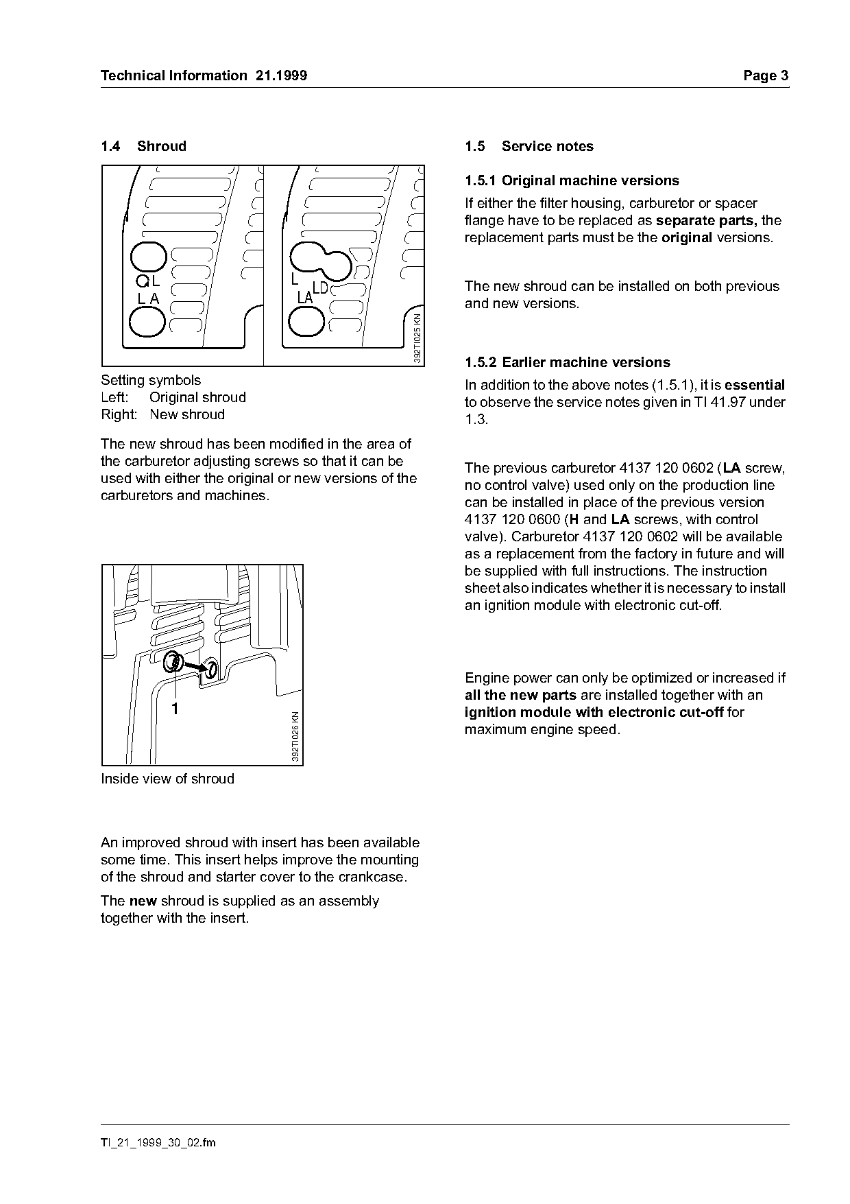
The new shroud has been modified in the area of
the carburetor adjusting screws so that it can be                The previous carburetor 4137 120 0602 (LA screw,
used with either the original or new versions of the             no control valve) used only on the production line
carburetors and machines.                                        can be installed in place of the previous version
                                                                 4137 120 0600 (H and LA screws, with control
                                                                 valve). Carburetor 4137 120 0602 will be available
                                                                 as a replacement from the factory in future and will
                                                                 be supplied with full instructions. The instruction
                                                                 sheet also indicates whether it is necessary to install
                                                                 an ignition module with electronic cut-off.

                                                                 Engine power can only be optimized or increased if
                                                                 all the new parts are installed together with an
           1                                                     ignition module with electronic cut-off for
                               392TI026 KN

                                                                 maximum engine speed.

Inside view of shroud

An improved shroud with insert has been available
some time. This insert helps improve the mounting
of the shroud and starter cover to the crankcase.
The new shroud is supplied as an assembly
together with the insert.

TI_21_1999_30_02.fm
Page 4 of 8
Text of page 4 — search, copy, screen readers
Page 4                                                                                       Technical Information 21.1999

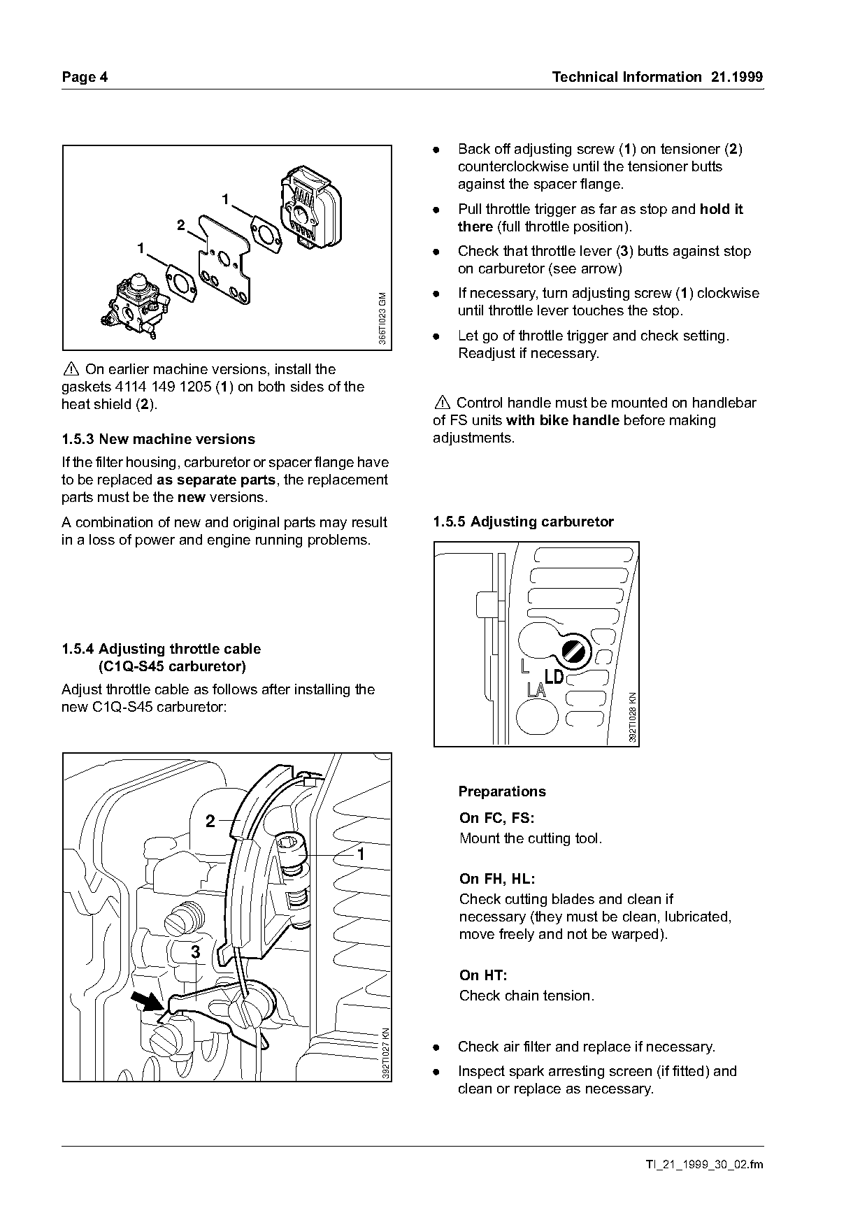
                                                                          .   Back off adjusting screw (1) on tensioner (2)
                                                                              counterclockwise until the tensioner butts
                                                                              against the spacer flange.
                               1
                                                                          .   Pull throttle trigger as far as stop and hold it
                   2                                                          there (full throttle position).
            1                                                             .   Check that throttle lever (3) butts against stop
                                                                              on carburetor (see arrow)
                                                                          .   If necessary, turn adjusting screw (1) clockwise

                                                        366TI023 GM
                                                                              until throttle lever touches the stop.
                                                                          .   Let go of throttle trigger and check setting.
                                                                              Readjust if necessary.
! On earlier machine versions, install the
gaskets 4114 149 1205 (1) on both sides of the
heat shield (2).                                                          ! Control handle must be mounted on handlebar
                                                                          of FS units with bike handle before making
1.5.3 New machine versions                                                adjustments.
If the filter housing, carburetor or spacer flange have
to be replaced as separate parts, the replacement
parts must be the new versions.
A combination of new and original parts may result                        1.5.5 Adjusting carburetor
in a loss of power and engine running problems.

1.5.4 Adjusting throttle cable
      (C1Q-S45 carburetor)
                                                                                            LD
Adjust throttle cable as follows after installing the
                                                                                                          392TI028 KN

new C1Q-S45 carburetor:

                                                                              Preparations

                           2                                                  On FC, FS:
                                                                              Mount the cutting tool.
                                                 1
                                                                              On FH, HL:
                                                                              Check cutting blades and clean if
                                                                              necessary (they must be clean, lubricated,
                                                                              move freely and not be warped).
                       3
                                                                              On HT:
                                                                              Check chain tension.
                                                            392TI027 KN

                                                                          .   Check air filter and replace if necessary.
                                                                          .   Inspect spark arresting screen (if fitted) and
                                                                              clean or replace as necessary.

                                                                                                                        TI_21_1999_30_02.fm
Page 5 of 8
Text of page 5 — search, copy, screen readers
Technical Information 21.1999                                                                          Page 5

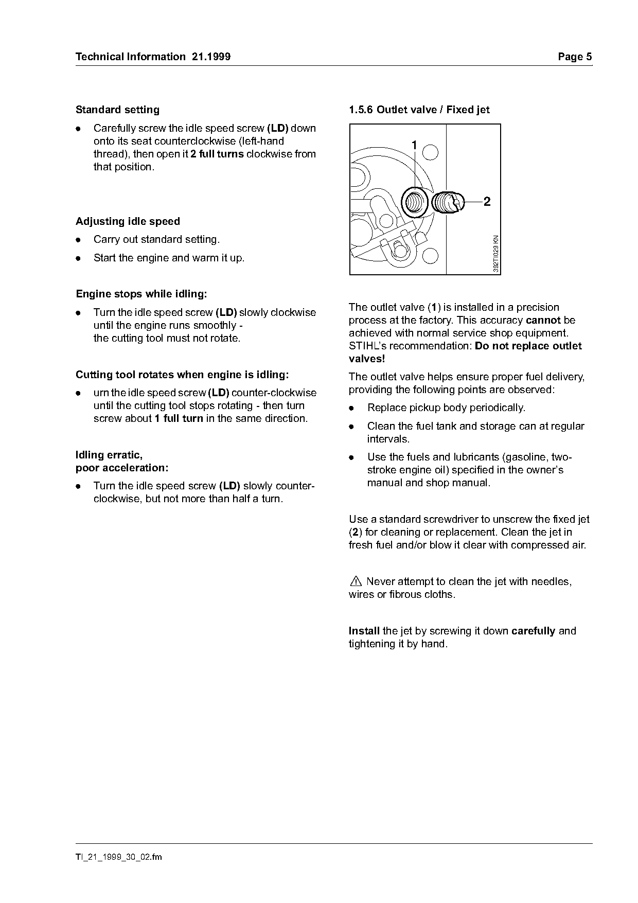
Standard setting                                        1.5.6 Outlet valve / Fixed jet
.   Carefully screw the idle speed screw (LD) down
    onto its seat counterclockwise (left-hand                        1
    thread), then open it 2 full turns clockwise from
    that position.

                                                                                     2
Adjusting idle speed
.   Carry out standard setting.

                                                                                         392TI029 KN
.   Start the engine and warm it up.

Engine stops while idling:
.   Turn the idle speed screw (LD) slowly clockwise     The outlet valve (1) is installed in a precision
    until the engine runs smoothly -                    process at the factory. This accuracy cannot be
    the cutting tool must not rotate.                   achieved with normal service shop equipment.
                                                        STIHL’s recommendation: Do not replace outlet
                                                        valves!
Cutting tool rotates when engine is idling:             The outlet valve helps ensure proper fuel delivery,
.   urn the idle speed screw (LD) counter-clockwise     providing the following points are observed:
    until the cutting tool stops rotating - then turn   .   Replace pickup body periodically.
    screw about 1 full turn in the same direction.
                                                        .   Clean the fuel tank and storage can at regular
                                                            intervals.
Idling erratic,                                         .   Use the fuels and lubricants (gasoline, two-
poor acceleration:                                          stroke engine oil) specified in the owner’s
.   Turn the idle speed screw (LD) slowly counter-          manual and shop manual.
    clockwise, but not more than half a turn.
                                                        Use a standard screwdriver to unscrew the fixed jet
                                                        (2) for cleaning or replacement. Clean the jet in
                                                        fresh fuel and/or blow it clear with compressed air.

                                                        ! Never attempt to clean the jet with needles,
                                                        wires or fibrous cloths.

                                                        Install the jet by screwing it down carefully and
                                                        tightening it by hand.

TI_21_1999_30_02.fm
Page 6 of 8
Text of page 6 — search, copy, screen readers
Page 6                                                                   Technical Information 21.1999

1.5.7 Filter housing / Choke shutter
Only combinations of the original or new versions of
the parts may be installed together. Do not mix
original parts with the new versions.

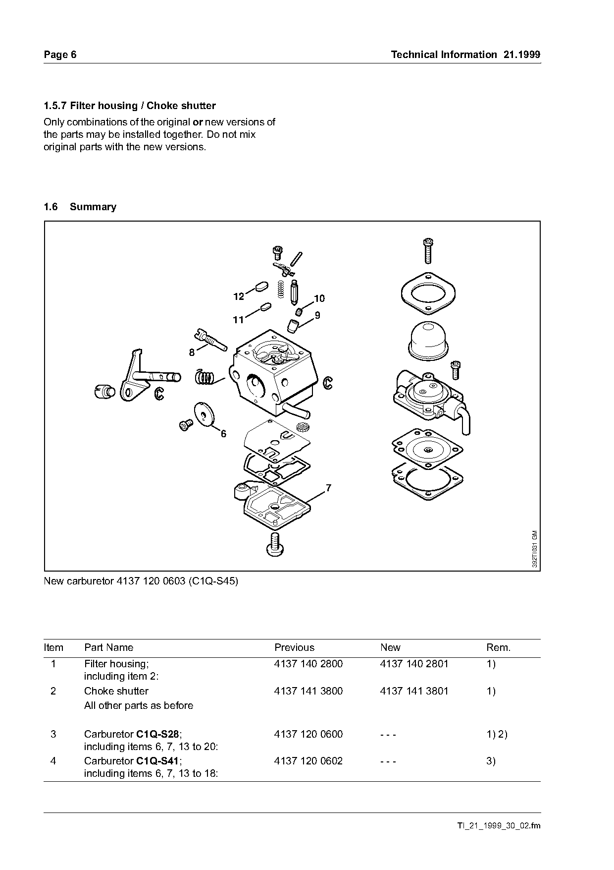
1.6    Summary

                                               12          10

                                               11              9


                                                                                                        392TI031 GM

New carburetor 4137 120 0603 (C1Q-S45)

Item     Part Name                                  Previous           New                   Rem.
 1       Filter housing;                            4137 140 2800      4137 140 2801         1)
         including item 2:
 2       Choke shutter                              4137 141 3800      4137 141 3801         1)
         All other parts as before

 3       Carburetor C1Q-S28;                        4137 120 0600      ---                   1) 2)
         including items 6, 7, 13 to 20:
 4       Carburetor C1Q-S41;                        4137 120 0602      ---                   3)
         including items 6, 7, 13 to 18:

                                                                                       TI_21_1999_30_02.fm
Page 7 of 8
Text of page 7 — search, copy, screen readers
Technical Information 21.1999                                                                        Page 7

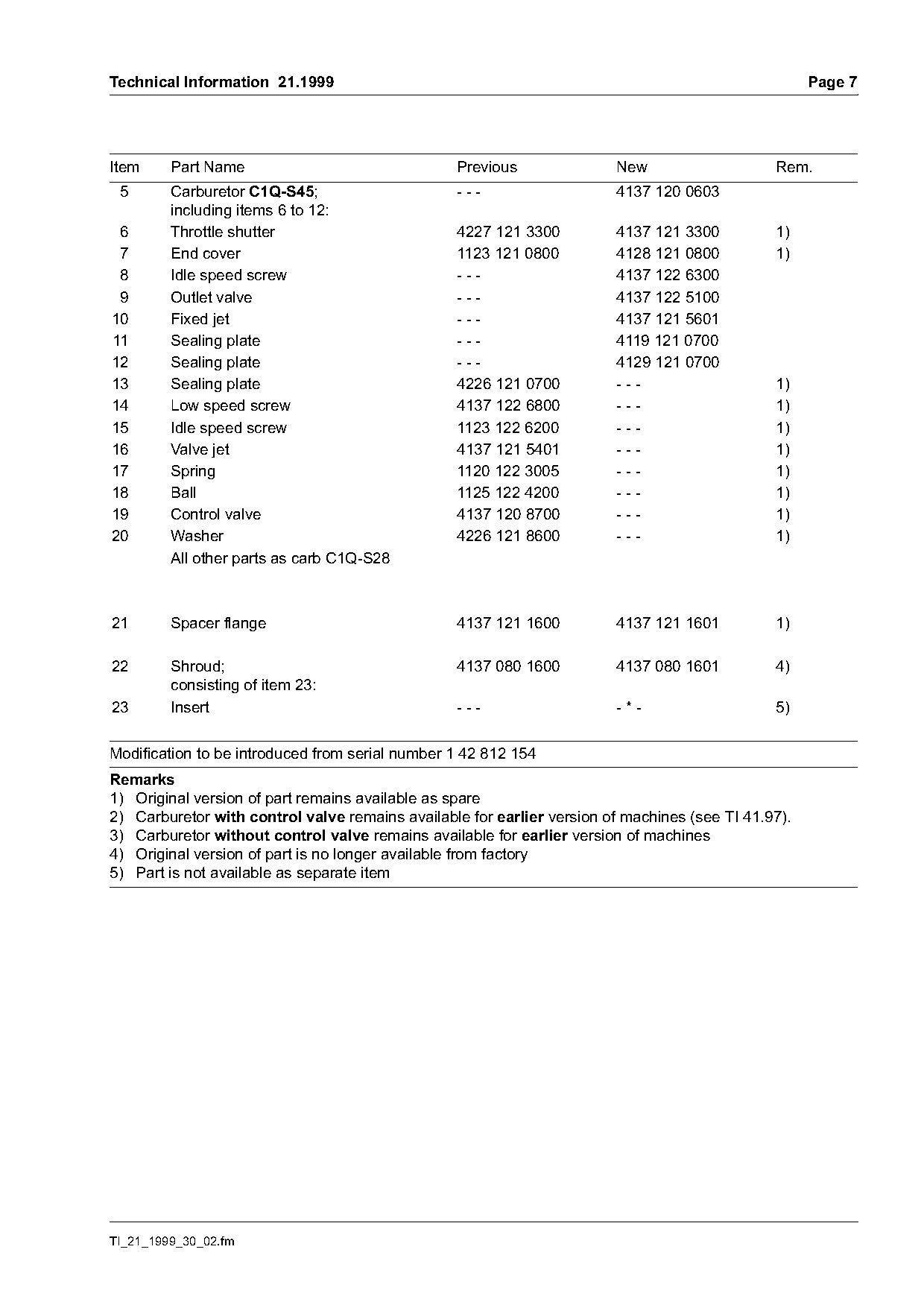
Item     Part Name                               Previous               New                    Rem.
 5       Carburetor C1Q-S45;                     ---                    4137 120 0603
         including items 6 to 12:
 6       Throttle shutter                        4227 121 3300          4137 121 3300          1)
 7       End cover                               1123 121 0800          4128 121 0800          1)
 8       Idle speed screw                        ---                    4137 122 6300
 9       Outlet valve                            ---                    4137 122 5100
10       Fixed jet                               ---                    4137 121 5601
11       Sealing plate                           ---                    4119 121 0700
12       Sealing plate                           ---                    4129 121 0700
13       Sealing plate                           4226 121 0700          ---                    1)
14       Low speed screw                         4137 122 6800          ---                    1)
15       Idle speed screw                        1123 122 6200          ---                    1)
16       Valve jet                               4137 121 5401          ---                    1)
17       Spring                                  1120 122 3005          ---                    1)
18       Ball                                    1125 122 4200          ---                    1)
19       Control valve                           4137 120 8700          ---                    1)
20       Washer                                  4226 121 8600          ---                    1)
         All other parts as carb C1Q-S28

21       Spacer flange                           4137 121 1600          4137 121 1601          1)

22       Shroud;                                 4137 080 1600          4137 080 1601          4)
         consisting of item 23:
23       Insert                                  ---                    -*-                    5)

Modification to be introduced from serial number 1 42 812 154
Remarks
1) Original version of part remains available as spare
2) Carburetor with control valve remains available for earlier version of machines (see TI 41.97).
3) Carburetor without control valve remains available for earlier version of machines
4) Original version of part is no longer available from factory
5) Part is not available as separate item

TI_21_1999_30_02.fm
Page 8 of 8
Text of page 8 — search, copy, screen readers
Page 8                                           Technical Information 21.1999

Last Technical Information on   STIHL FH 75:                             47.98
                                STIHL HL 75, 75 K:                       44.98
                                STIHL HT 70:                             35.98
                                STIHL HT 75:                           14.1999
                                STIHL FC 75:                             41.97
                                STIHL FS 75, 80, 85:                     41.97

© 1999 Andreas STIHL AG & Co.   Technical Documentation
  Waiblingen                    D1/MTK-na                                 6565

                                                             TI_21_1999_30_02.fm
Most of these PDFs embed fonts with a shifted character map, so the text above was recovered rather than copied — read it as a faithful but imperfect transcription, and treat the page image above each block as the authority where the two disagree — the figures exist only there, because they are vector drawings that text extraction cannot keep.