Technical Information · issue 37 of 1999
066 arctic: Handle heating with optimized heat out
Model 066 arctic Chainsaws - Series 1122
IssueTI 37/1999
Engine family 1122
Part changes (3)
| Was | Becomes | What the bulletin says |
|---|---|---|
| 1122 400 1218 | 1122 400 1202 | The previous flywheel 1122 400 1218 will be replaced by the new version 1122 400 1202. |
| 1128 404 3501 | 1128 404 3502 | Left: Previous version 1128 404 3501 Right: New version 1128 404 3502 The previous generator 1128 404 3501 with one winding will be replaced by a new version 1128 404 3502 with two windings - one for handle heating, one for carburetor heating. |
| 1122 440 3009 | 1122 440 3002 | The previous wiring harness 1122 440 3009 will be replaced by the version 1122 440 3002. |
Full text
Page 1 of 3
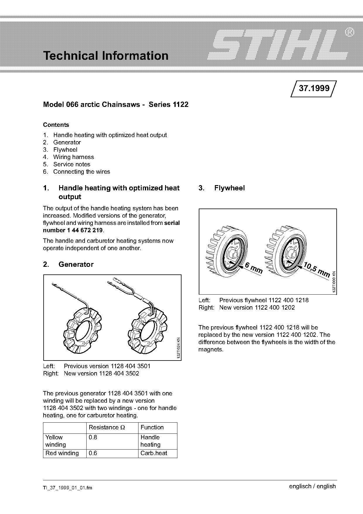
Text of page 1 — search, copy, screen readers
Technical Information

                                                                                                       37.1999
Model 066 arctic Chainsaws - Series 1122

Contents
1.   Handle heating with optimized heat output
2.   Generator
3.   Flywheel
4.   Wiring harness
5.   Service notes
6.   Connecting the wires

1.    Handle heating with optimized heat                         3.   Flywheel
      output
The output of the handle heating system has been
increased. Modified versions of the generator,
flywheel and wiring harness are installed from serial
number 1 44 672 219.
The handle and carburetor heating systems now
operate independent of one another.

2.    Generator                                                                   6m                    10,
                                                                                                            5m
                                                                                      m
                                                                                                                m

                                                                                                                    132TI000 KN
                                                                 Left: Previous flywheel 1122 400 1218
                                                                 Right: New version 1122 400 1202

                                                                 The previous flywheel 1122 400 1218 will be
                                                                 replaced by the new version 1122 400 1202. The
                                                   132TI024 KN

                                                                 difference between the flywheels is the width of the
                                                                 magnets.

Left: Previous version 1128 404 3501
Right: New version 1128 404 3502

The previous generator 1128 404 3501 with one
winding will be replaced by a new version
1128 404 3502 with two windings - one for handle
heating, one for carburetor heating.

                 Resistance Ω        Function
Yellow           0.8                 Handle
winding                              heating
Red winding      0.6                 Carb.heat

TI_37_1999_01_01.fm                                                                                englisch / english
Page 2 of 3
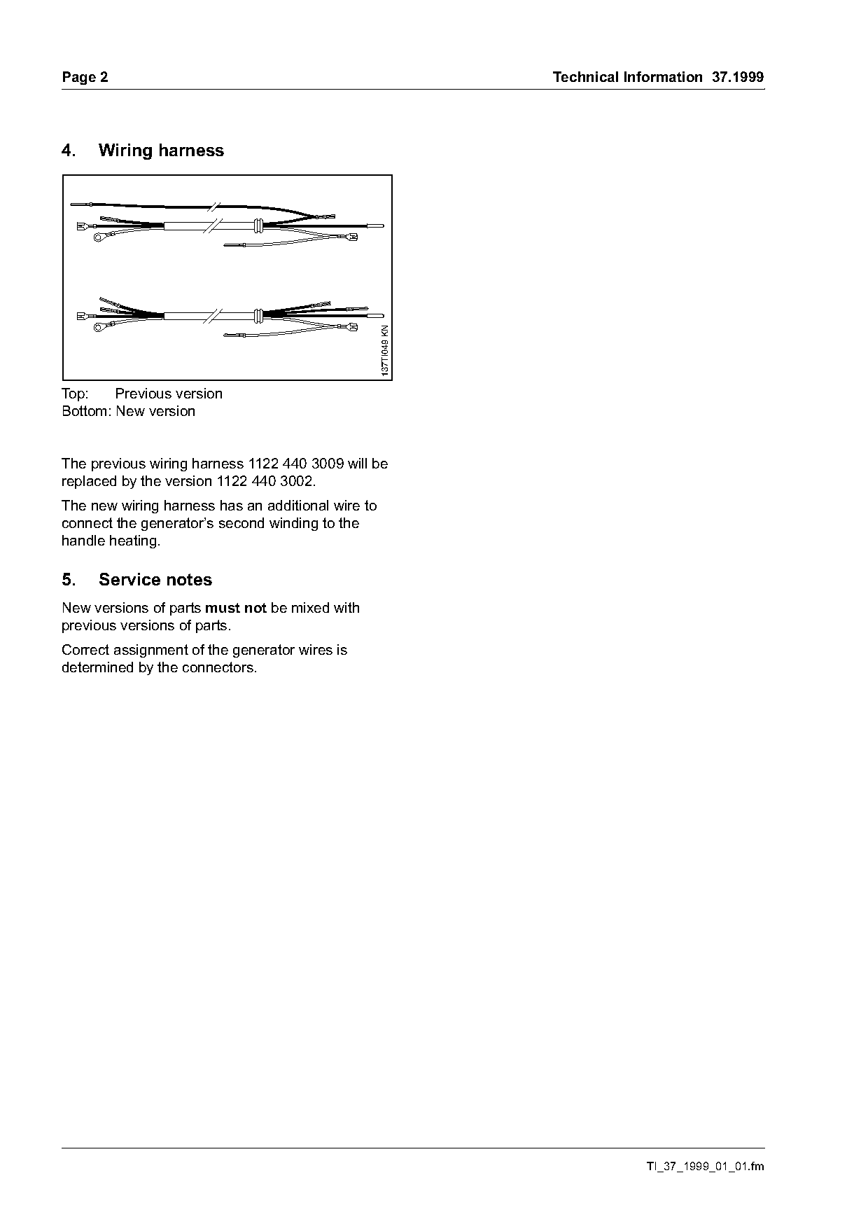
Text of page 2 — search, copy, screen readers
Page 2                                                           Technical Information 37.1999

4.   Wiring harness

                                                   137TI049 KN
Top:    Previous version
Bottom: New version

The previous wiring harness 1122 440 3009 will be
replaced by the version 1122 440 3002.
The new wiring harness has an additional wire to
connect the generator’s second winding to the
handle heating.

5.   Service notes
New versions of parts must not be mixed with
previous versions of parts.
Correct assignment of the generator wires is
determined by the connectors.

                                                                             TI_37_1999_01_01.fm
Page 3 of 3
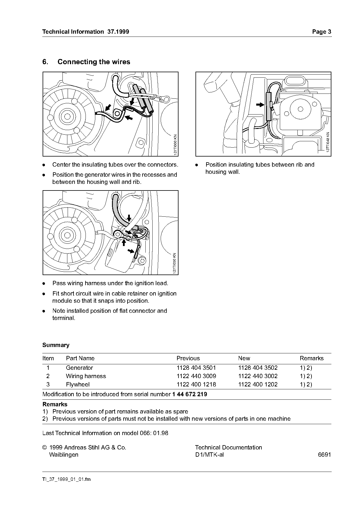
Text of page 3 — search, copy, screen readers
Technical Information 37.1999                                                                                          Page 3

6.        Connecting the wires

                                                                                                                             137TI048 KN
                                                           137TI000 KN
.       Center the insulating tubes over the connectors.                  .    Position insulating tubes between rib and
.       Position the generator wires in the recesses and                       housing wall.
        between the housing wall and rib.
                                                          137TI050 KN

.       Pass wiring harness under the ignition lead.
.       Fit short circuit wire in cable retainer on ignition
        module so that it snaps into position.
.       Note installed position of flat connector and
        terminal.

Summary

Item         Part Name                                              Previous               New                    Remarks
    1        Generator                                              1128 404 3501          1128 404 3502          1) 2)
    2        Wiring harness                                         1122 440 3009          1122 440 3002          1) 2)
    3        Flywheel                                               1122 400 1218          1122 400 1202          1) 2)
Modification to be introduced from serial number 1 44 672 219
Remarks
1) Previous version of part remains available as spare
2) Previous versions of parts must not be installed with new versions of parts in one machine

Last Technical Information on model 066: 01.98

© 1999 Andreas Stihl AG & Co.                                             Technical Documentation
  Waiblingen                                                              D1/MTK-al                                        6691

TI_37_1999_01_01.fm
Most of these PDFs embed fonts with a shifted character map, so the text above was recovered rather than copied — read it as a faithful but imperfect transcription, and treat the page image above each block as the authority where the two disagree — the figures exist only there, because they are vector drawings that text extraction cannot keep.