Technical Information · issue 42 of 1999
Cutter bars; Bump guard; ElastoStart
Model HS 75 and HS 80 Hedge Trimmers - Series 4226
IssueTI 42/1999
Part changes (1)
| Was | Becomes | What the bulletin says |
|---|---|---|
| 0000 190 3400 | 0000 190 3403 | ElastoStart (starter rope) ElastoStart 0000 190 3400 will be replaced by ElastoStart 0000 190 3403 to achieve a further improvement in operation. |
Full text
Page 1 of 4
Text of page 1 — search, copy, screen readers
Technical Information

                                                                                                       42.1999
Model HS 75 and HS 80 Hedge Trimmers - Series 4226

Contents
1. Cutter bars
2. Bump guard (special accessory)
3. ElastoStart (starter rope)

1.    Cutter bars
The cutting blade assembly on models HS 75 and                   To comply with requests from the field, cutting blade
HS 80 will be modified to further improve service-               lengths will also be quoted in inches in future. For
friendliness.                                                    assignments see the summary.
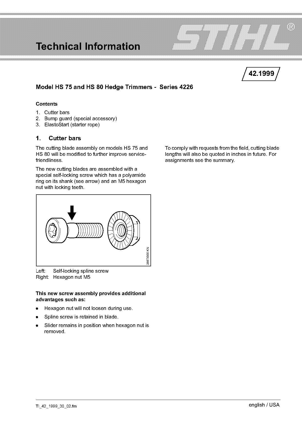
The new cutting blades are assembled with a
special self-locking screw which has a polyamide
ring on its shank (see arrow) and an M5 hexagon
nut with locking teeth.
                                                   366TI000 KN

Left: Self-locking spline screw
Right: Hexagon nut M5

This new screw assembly provides additional
advantages such as:
.    Hexagon nut will not loosen during use.
.    Spline screw is retained in blade.
.    Slider remains in position when hexagon nut is
     removed.

TI_42_1999_30_02.fm                                                                                    english / USA
Page 2 of 4
Text of page 2 — search, copy, screen readers
Page 2                                                             Technical Information 42.1999


                                                                                        2
         6

                                                                                        7
                                                                                        5
         11


                                                                                                  366TI025 KN
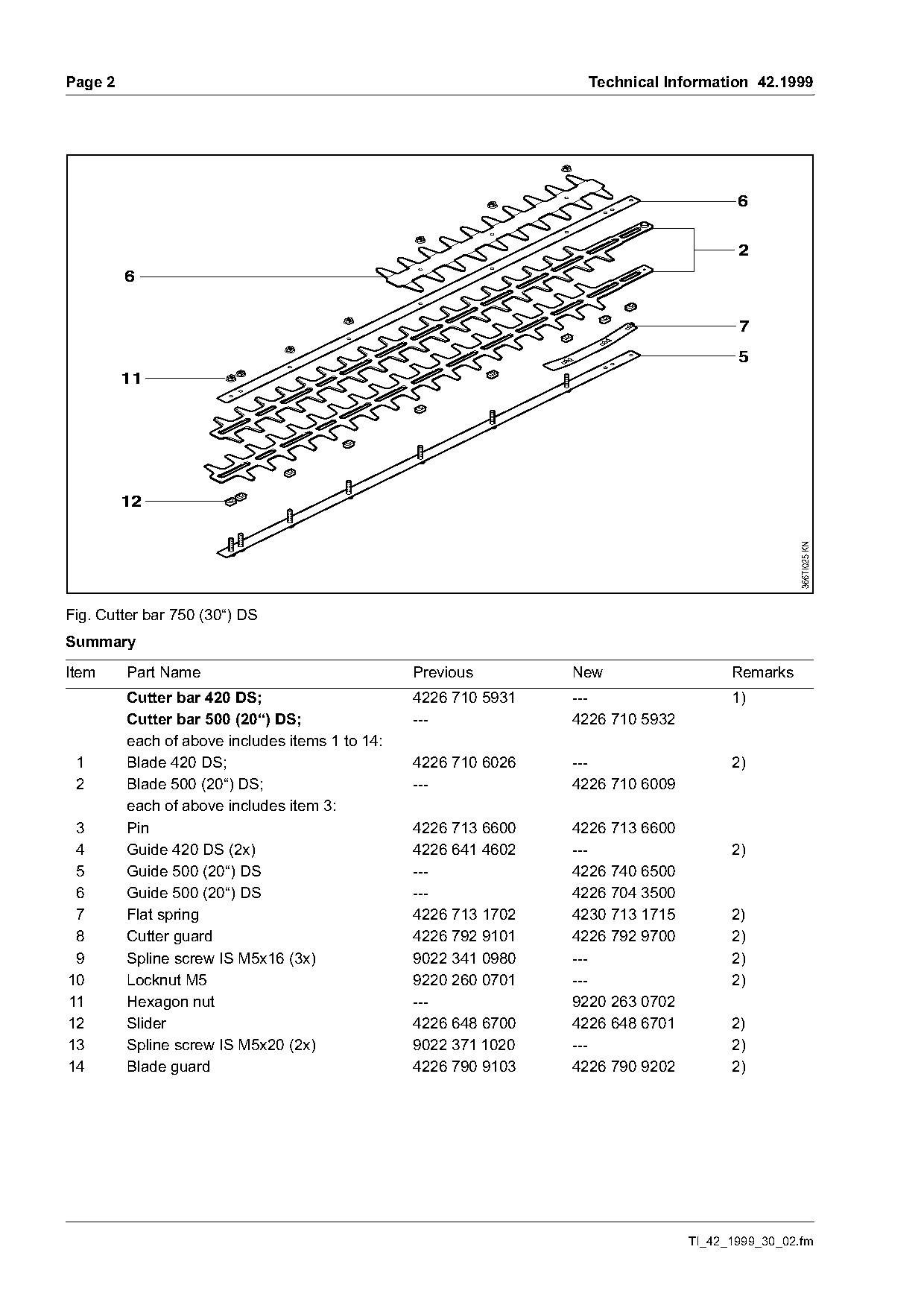
Fig. Cutter bar 750 (30“) DS
Summary

Item     Part Name                               Previous        New                   Remarks
         Cutter bar 420 DS;                      4226 710 5931   ---                   1)
         Cutter bar 500 (20“) DS;                ---             4226 710 5932
         each of above includes items 1 to 14:
 1       Blade 420 DS;                           4226 710 6026   ---                   2)
 2       Blade 500 (20“) DS;                     ---             4226 710 6009
         each of above includes item 3:
 3       Pin                                     4226 713 6600   4226 713 6600
 4       Guide 420 DS (2x)                       4226 641 4602   ---                   2)
 5       Guide 500 (20“) DS                      ---             4226 740 6500
 6       Guide 500 (20“) DS                      ---             4226 704 3500
 7       Flat spring                             4226 713 1702   4230 713 1715         2)
 8       Cutter guard                            4226 792 9101   4226 792 9700         2)
 9       Spline screw IS M5x16 (3x)              9022 341 0980   ---                   2)
10       Locknut M5                              9220 260 0701   ---                   2)
11       Hexagon nut                             ---             9220 263 0702
12       Slider                                  4226 648 6700   4226 648 6701         2)
13       Spline screw IS M5x20 (2x)              9022 371 1020   ---                   2)
14       Blade guard                             4226 790 9103   4226 790 9202         2)

                                                                                 TI_42_1999_30_02.fm
Page 3 of 4
Text of page 3 — search, copy, screen readers
Technical Information 42.1999                                                          Page 3

Item     Part Name                                Previous        New             Remarks
         Cutter bar 550 DS;                       4226 710 5901   ---             1)
         Cutter bar 600 (24“) DS;                 ---             4226 710 5903
         each of above includes items 1 to 14:
 1       Blade 550 DS;                            4226 710 6020   ---             2)
 2       Blade 600 (24“) DS;                      ---             4226 710 6019
         each of above includes item 3:
 3       Pin                                      4226 713 6600   4226 713 6600
 4       Guide 550 DS (2x)                        4226 641 4600   ---             2)
 5       Guide 600 (24“) DS                       ---             4226 740 6501
 6       Guide 600 (24“) DS                       ---             4226 704 3501
 7       Flat spring                              4226 713 1700   4230 713 1715   2)
 8       Cutter guard                             4226 792 9101   4226 792 9700   2)
 9       Spline screw IS M5x16 (4x)               9022 341 0980   ---             2)
10       Locknut M5                               9220 260 0701   ---             2)
11       Hexagon nut                              ---             9220 263 0702
12       Slider                                   4226 648 6700   4226 648 6701   2)
13       Spline screw IS M5x20 (2x)               9022 371 1020   ---             2)
14       Blade guard                              4226 790 9100   4226 790 9200   2)

         Cutter bar 700 DS;                       4226 710 5941   ---             1)
         Cutter bar 750 (30“) DS;                 ---             4226 710 5942
         each of above includes items 1 to 14:
 1       Blade 700 DS;                            4226 710 6023   ---             2)
 2       Blade 750 (30“) DS;                      ---             4226 710 6031
         each of above includes item 3:
 3       Pin                                      4226 713 6600   4226 713 6600
 4       Guide 700 DS (2x)                        4226 641 4601   ---             2)
 5       Guide 750 (30“) DS                       ---             4226 740 6502
 6       Guide 750 (30“) DS                       ---             4226 704 3502
 7       Flat spring                              4226 713 1701   4230 713 1715   2)
 8       Cutter guard                             4226 792 9101   4226 792 9700   2)
 9       Spline screw IS M5x16 (5x)               9022 341 0980   ---             2)
10       Locknut M5                               9220 260 0701   ---             2)
11       Hexagon nut                              ---             9220 263 0702
12       Slider                                   4226 648 6700   4226 648 6701
13       Spline screw IS M5x20 (2x)               9022 371 1020   ---             2)
14       Blade guard                              4226 790 9104   4226 790 9203   2)

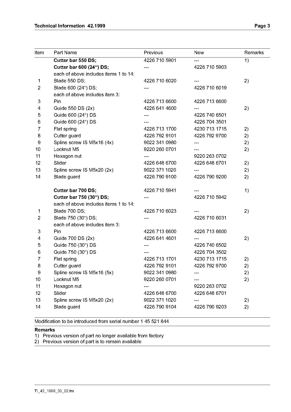
Modification to be introduced from serial number 1 45 521 844
Remarks
1) Previous version of part no longer available from factory
2) Previous version of part is to remain available

TI_42_1999_30_02.fm
Page 4 of 4
Text of page 4 — search, copy, screen readers
Page 4                                                                               Technical Information 42.1999

2.     Bump guard (special accessory)
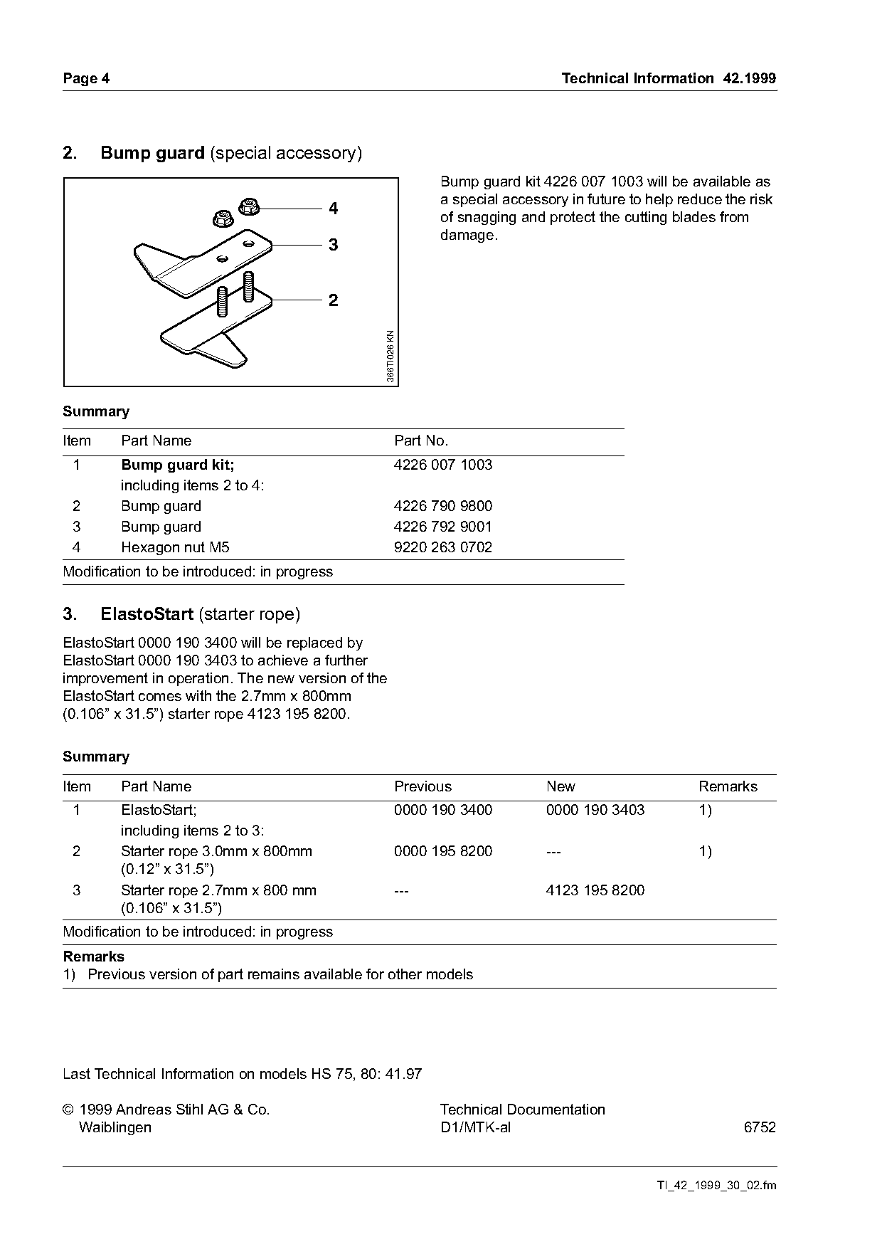
                                                               Bump guard kit 4226 007 1003 will be available as
                                                               a special accessory in future to help reduce the risk
                                         4                     of snagging and protect the cutting blades from
                                                               damage.
                                         3


                                                366TI026 KN

Summary

Item     Part Name                                       Part No.
 1       Bump guard kit;                                 4226 007 1003
         including items 2 to 4:
 2       Bump guard                                      4226 790 9800
 3       Bump guard                                      4226 792 9001
 4       Hexagon nut M5                                  9220 263 0702
Modification to be introduced: in progress

3.     ElastoStart (starter rope)
ElastoStart 0000 190 3400 will be replaced by
ElastoStart 0000 190 3403 to achieve a further
improvement in operation. The new version of the
ElastoStart comes with the 2.7mm x 800mm
(0.106” x 31.5”) starter rope 4123 195 8200.

Summary

Item     Part Name                                       Previous              New                      Remarks
 1       ElastoStart;                                    0000 190 3400         0000 190 3403            1)
         including items 2 to 3:
 2       Starter rope 3.0mm x 800mm                      0000 195 8200         ---                      1)
         (0.12” x 31.5”)
 3       Starter rope 2.7mm x 800 mm                     ---                   4123 195 8200
         (0.106” x 31.5”)
Modification to be introduced: in progress
Remarks
1) Previous version of part remains available for other models

Last Technical Information on models HS 75, 80: 41.97

© 1999 Andreas Stihl AG & Co.                                  Technical Documentation
  Waiblingen                                                   D1/MTK-al                                       6752

                                                                                                 TI_42_1999_30_02.fm
Most of these PDFs embed fonts with a shifted character map, so the text above was recovered rather than copied — read it as a faithful but imperfect transcription, and treat the page image above each block as the authority where the two disagree — the figures exist only there, because they are vector drawings that text extraction cannot keep.