Technical Information · issue 7 of 2000
New KW 85 PowerSweep
IssueTI 7/2000
Full text
Page 1 of 6
Text of page 1 — search, copy, screen readers
Technical Information

                                                                                         07.2000
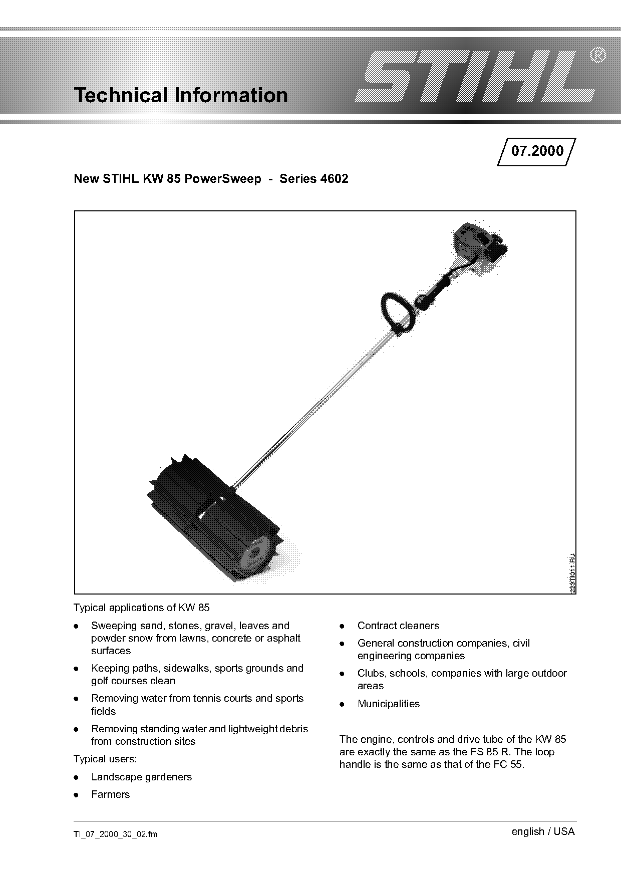
New STIHL KW 85 PowerSweep - Series 4602

Typical applications of KW 85
.   Sweeping sand, stones, gravel, leaves and        .   Contract cleaners
    powder snow from lawns, concrete or asphalt
                                                     .   General construction companies, civil
    surfaces
                                                         engineering companies
.   Keeping paths, sidewalks, sports grounds and     .   Clubs, schools, companies with large outdoor
    golf courses clean                                   areas
.   Removing water from tennis courts and sports
                                                     .   Municipalities
    fields
.   Removing standing water and lightweight debris
    from construction sites                          The engine, controls and drive tube of the KW 85
                                                     are exactly the same as the FS 85 R. The loop
Typical users:
                                                     handle is the same as that of the FC 55.
.   Landscape gardeners
.   Farmers

TI_07_2000_30_02.fm                                                                       english / USA
Page 2 of 6
Text of page 2 — search, copy, screen readers
Page 2                                                                                     Technical Information 07.2000

Contents
1.    Technical Description
2.    Specifications
3.    Accessories for User
4.    Special Servicing Tools
5.    Repairs
6.    Spare Parts

1.      Technical Description

1.1     Carburetor                                                     1.4   Sweeper drum assemblies
.     All position diaphragm carburetor with integral
      fuel pump
.     Only one adjusting screw (LD)                                               3                  6            3
.     Full-load fixed jet
.     Manual fuel pump
.     Balanced idle system (BIS)

1.2     Drive tube

                                                                                                                            223TI009 AM
Straight tube with rigid drive shaft supported in a                                              7
lubricated liner.

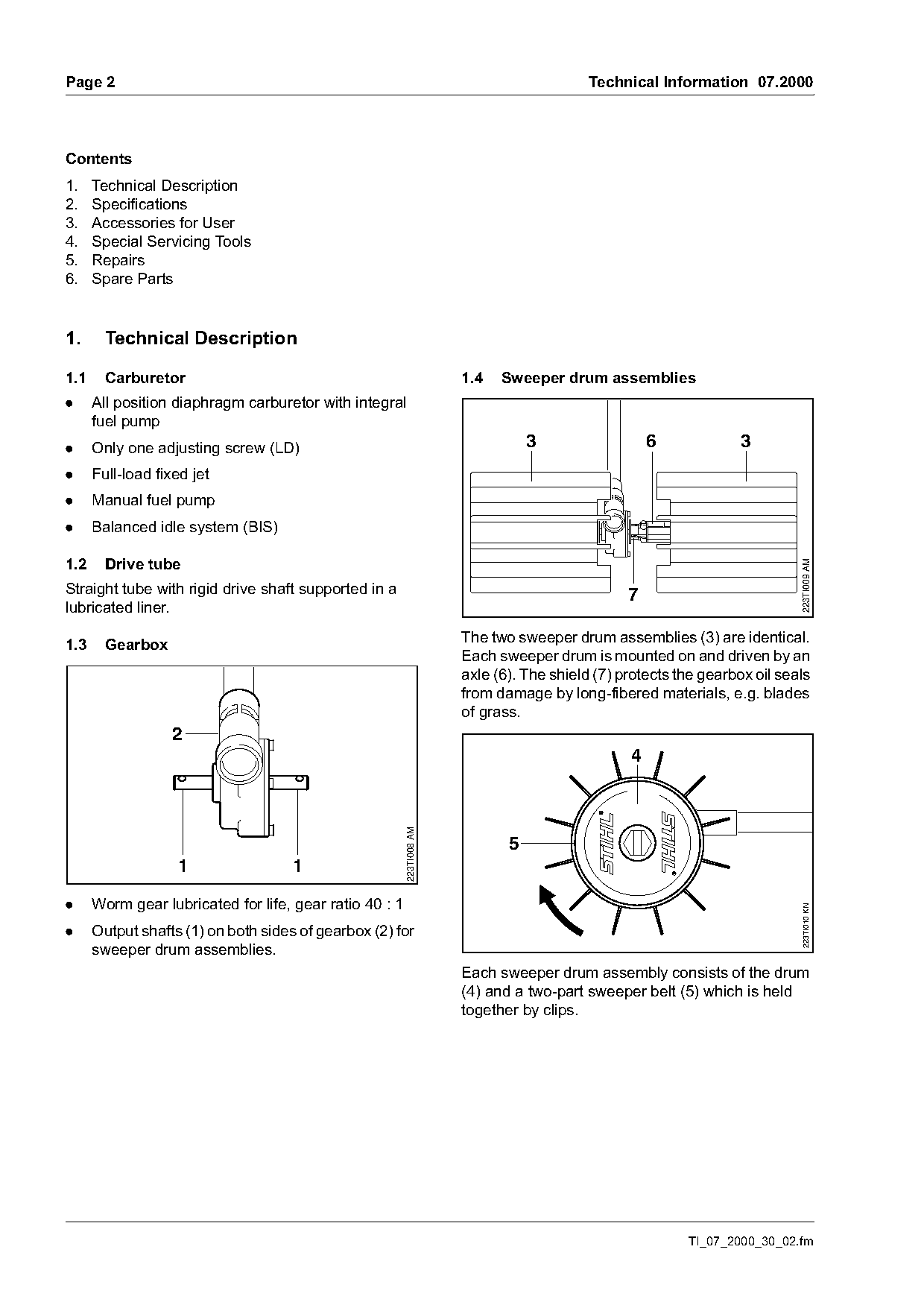
1.3     Gearbox                                                        The two sweeper drum assemblies (3) are identical.
                                                                       Each sweeper drum is mounted on and driven by an
                                                                       axle (6). The shield (7) protects the gearbox oil seals
                                                                       from damage by long-fibered materials, e.g. blades
                                                                       of grass.
                  2
                                                                                                 4
                                                         223TI008 AM

                                                                              5
                    1                1

.     Worm gear lubricated for life, gear ratio 40 : 1
                                                                                                                             223TI010 KN

.     Output shafts (1) on both sides of gearbox (2) for
      sweeper drum assemblies.
                                                                       Each sweeper drum assembly consists of the drum
                                                                       (4) and a two-part sweeper belt (5) which is held
                                                                       together by clips.

                                                                                                          TI_07_2000_30_02.fm
Page 3 of 6
Text of page 3 — search, copy, screen readers
Technical Information 07.2000                                                                      Page 3

2.    Specifications

2.1   Powerhead                                      2.4   Fuel System
Single cylinder two-stroke                           Fuel tank capacity:       0.44 l (14.9 oz)
engine                                               Fuel mix:                 Branded regular grade
Displacement:                  25.4 cm3                                        gasoline (89 octane
Bore:                          34 mm                                           minimum) and brand-
Stroke:                        28 mm                                           name two-stroke engine
                                                                               oil
Engine power to ISO 8893:      0.95 kW (1.3 bhp)
                               at 8,500 rpm          Mix ratio:                50:1 with STIHL 50:1 two-
                                                                               stroke engine oil
Idle speed                     2,800 rpm
Cut-off speed range without    9,700 up to
                                                     2.5   Ignition System
sweeper drums (electronic      11,300 rpm
speed governor)                                      Ignition module with integral electronic speed
                                                     governor
Rewind starter:                Single pawl system;
                               Elastostart grip      3.    Accessories for User
Starter rope:                  3 mm dia., 800 mm
                               long (31.5 in)
Clutch:
- Diameter:                    66.5 mm
- Clutch engages at:           4,000 rpm

2.2   Weight
Unit with sweeper drums        19.6 lbs (8.9 kg)

                                                                                                         223TI012 KN
2.3   Idle speed screw LD
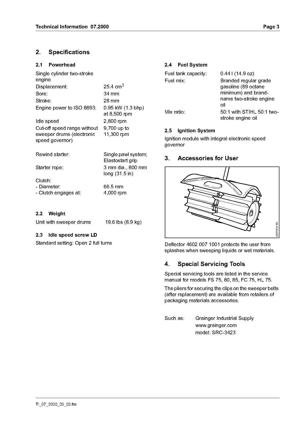
Standard setting: Open 2 full turns                  Deflector 4602 007 1001 protects the user from
                                                     splashes when sweeping liquids or wet materials.

                                                     4.    Special Servicing Tools
                                                     Special servicing tools are listed in the service
                                                     manual for models FS 75, 80, 85, FC 75, HL 75.
                                                     The pliers for securing the clips on the sweeper belts
                                                     (after replacement) are available from retailers of
                                                     packaging materials accessories.

                                                     Such as:      Grainger Industrial Supply
                                                                   www.grainger.com
                                                                   model: SRC-3423

TI_07_2000_30_02.fm
Page 4 of 6
Text of page 4 — search, copy, screen readers
Page 4                                                                                 Technical Information 07.2000

5.        Repairs
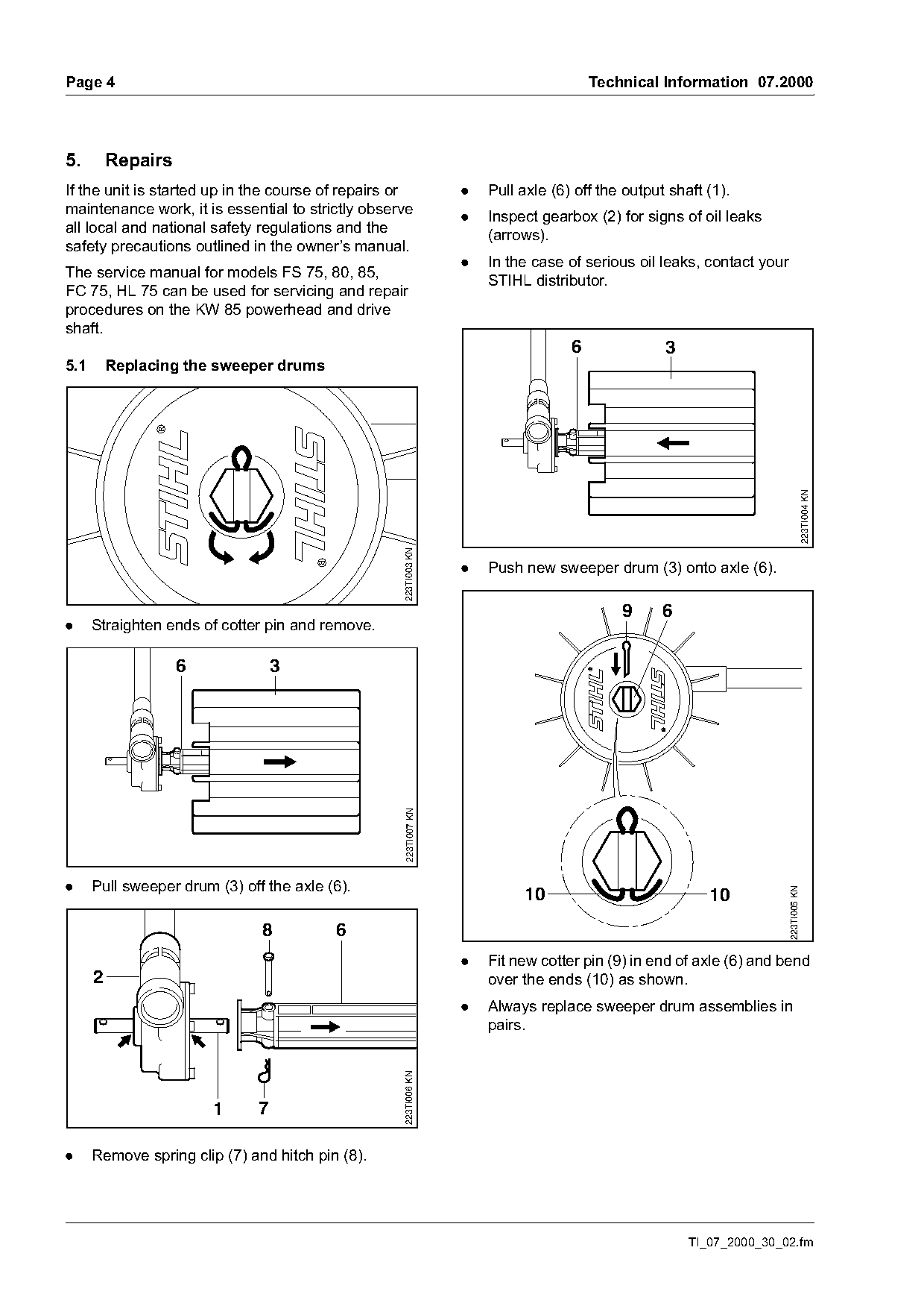
If the unit is started up in the course of repairs or             .   Pull axle (6) off the output shaft (1).
maintenance work, it is essential to strictly observe             .   Inspect gearbox (2) for signs of oil leaks
all local and national safety regulations and the                     (arrows).
safety precautions outlined in the owner’s manual.
                                                                  .   In the case of serious oil leaks, contact your
The service manual for models FS 75, 80, 85,
                                                                      STIHL distributor.
FC 75, HL 75 can be used for servicing and repair
procedures on the KW 85 powerhead and drive
shaft.
                                                                                   6              3
5.1       Replacing the sweeper drums

                                                                                                                                     223TI004 KN
                                                   223TI003 KN

                                                                  .   Push new sweeper drum (3) onto axle (6).

                                                                                           9      6
.     Straighten ends of cotter pin and remove.

                    6              3
                                                    223TI007 KN

.     Pull sweeper drum (3) off the axle (6).
                                                                                                                       223TI005 KN

                                                                           10                            10
                               8          6
                                                                  .   Fit new cotter pin (9) in end of axle (6) and bend
      2                                                               over the ends (10) as shown.
                                                                  .   Always replace sweeper drum assemblies in
                                                                      pairs.
                                                   223TI006 KN

                        1      7

.     Remove spring clip (7) and hitch pin (8).

                                                                                                      TI_07_2000_30_02.fm
Page 5 of 6
Text of page 5 — search, copy, screen readers
Technical Information 07.2000                                                                                            Page 5

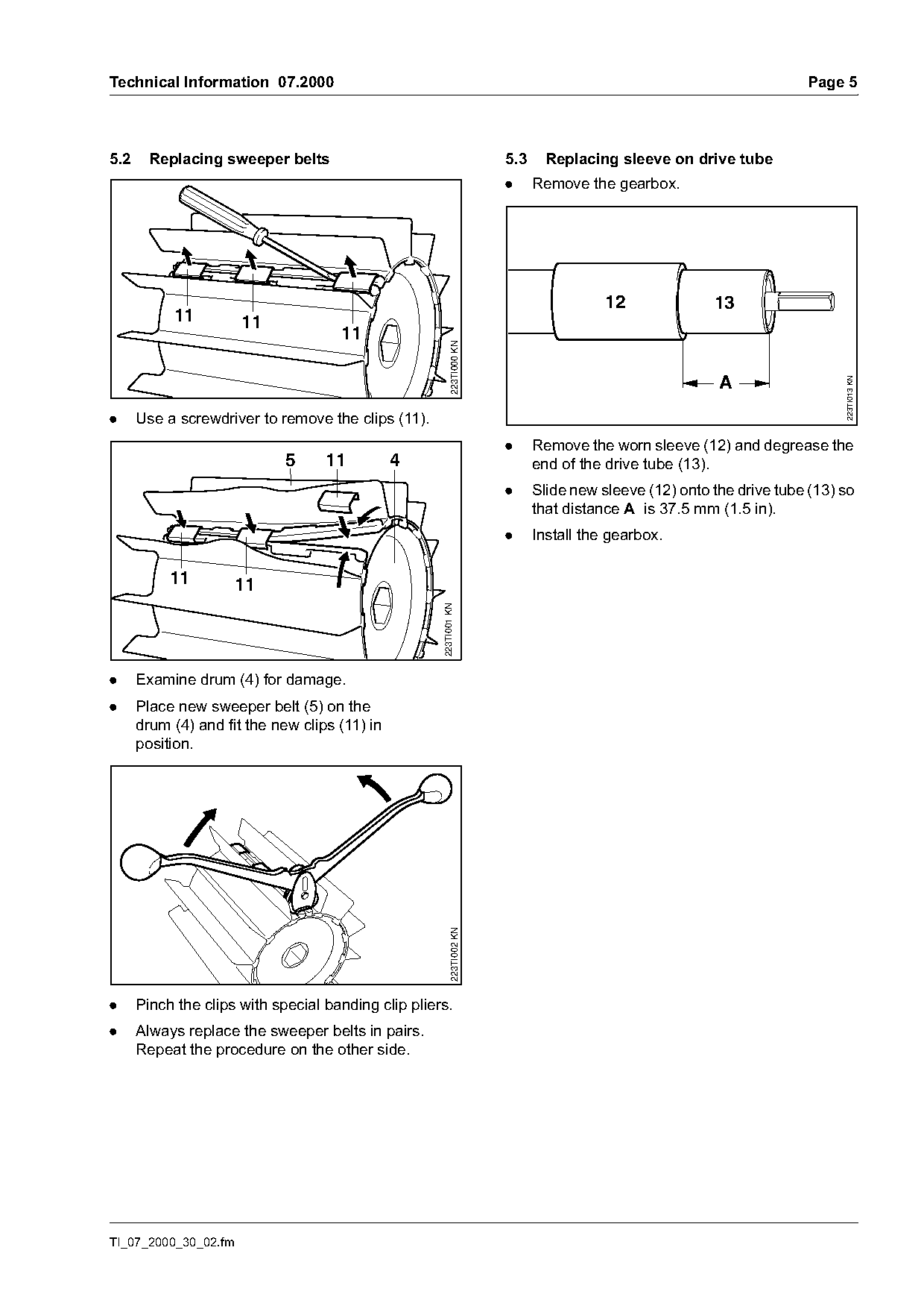
5.2     Replacing sweeper belts                                           5.3     Replacing sleeve on drive tube
                                                                          .     Remove the gearbox.

                                                                                           12              13
           11         11
                                     11

                                                            223TI000 KN
                                                                                                            A

                                                                                                                               223TI013 KN
.     Use a screwdriver to remove the clips (11).
                                                                          .     Remove the worn sleeve (12) and degrease the
                             5     11          4                                end of the drive tube (13).
                                                                          .     Slide new sleeve (12) onto the drive tube (13) so
                                                                                that distance A is 37.5 mm (1.5 in).
                                                                          .     Install the gearbox.

           11         11
                                                     223TI001 KN

.     Examine drum (4) for damage.
.     Place new sweeper belt (5) on the
      drum (4) and fit the new clips (11) in
      position.
                                                            223TI002 KN

.     Pinch the clips with special banding clip pliers.
.     Always replace the sweeper belts in pairs.
      Repeat the procedure on the other side.

TI_07_2000_30_02.fm
Page 6 of 6
Text of page 6 — search, copy, screen readers
Page 6                                                                  Technical Information 07.2000

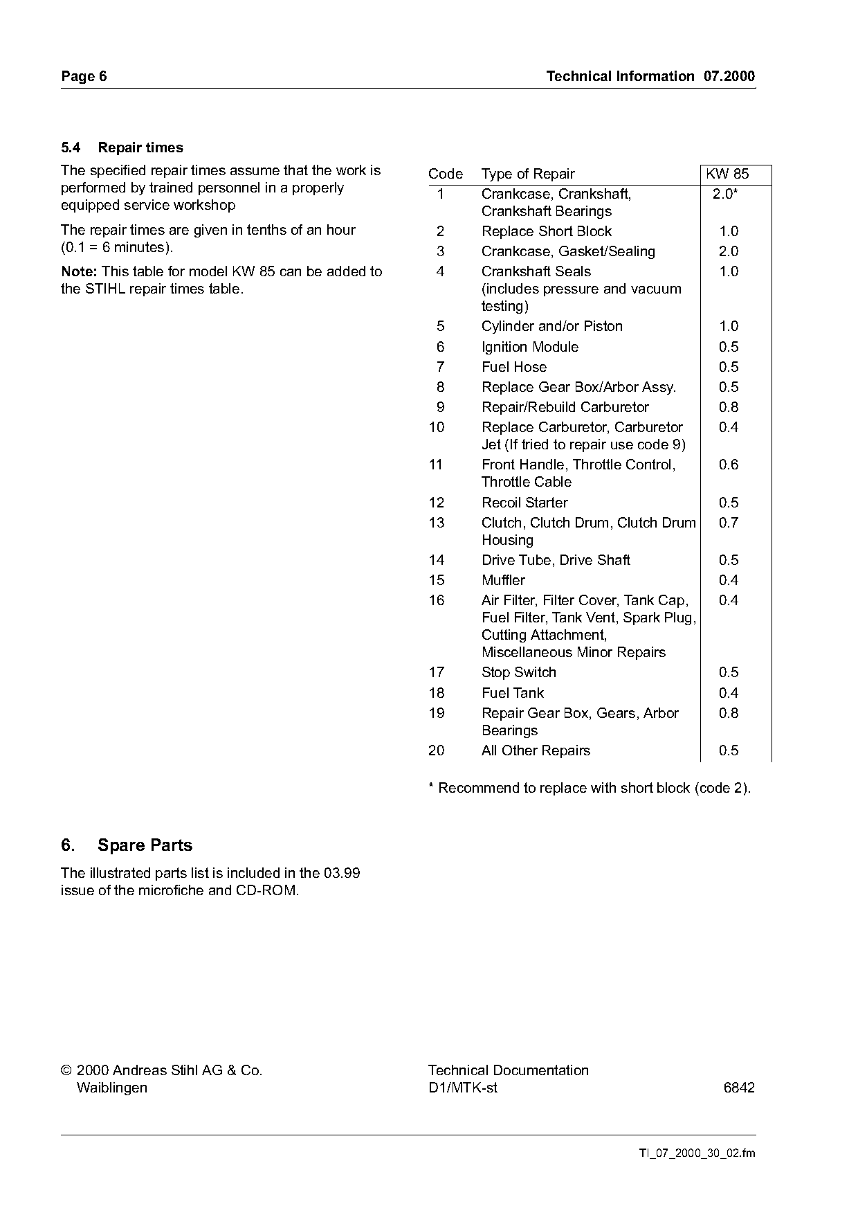
5.4   Repair times
The specified repair times assume that the work is    Code    Type of Repair                      KW 85
performed by trained personnel in a properly           1      Crankcase, Crankshaft,               2.0*
equipped service workshop                                     Crankshaft Bearings
The repair times are given in tenths of an hour        2      Replace Short Block                   1.0
(0.1 = 6 minutes).                                     3      Crankcase, Gasket/Sealing             2.0
Note: This table for model KW 85 can be added to       4      Crankshaft Seals                      1.0
the STIHL repair times table.                                 (includes pressure and vacuum
                                                              testing)
                                                       5      Cylinder and/or Piston                1.0
                                                       6      Ignition Module                       0.5
                                                       7      Fuel Hose                             0.5
                                                       8      Replace Gear Box/Arbor Assy.          0.5
                                                       9      Repair/Rebuild Carburetor             0.8
                                                      10      Replace Carburetor, Carburetor        0.4
                                                              Jet (If tried to repair use code 9)
                                                      11      Front Handle, Throttle Control,       0.6
                                                              Throttle Cable
                                                      12      Recoil Starter                        0.5
                                                      13      Clutch, Clutch Drum, Clutch Drum      0.7
                                                              Housing
                                                      14      Drive Tube, Drive Shaft               0.5
                                                      15      Muffler                               0.4
                                                      16      Air Filter, Filter Cover, Tank Cap,   0.4
                                                              Fuel Filter, Tank Vent, Spark Plug,
                                                              Cutting Attachment,
                                                              Miscellaneous Minor Repairs
                                                      17      Stop Switch                           0.5
                                                      18      Fuel Tank                             0.4
                                                      19      Repair Gear Box, Gears, Arbor         0.8
                                                              Bearings
                                                      20      All Other Repairs                     0.5

                                                      * Recommend to replace with short block (code 2).

6.    Spare Parts
The illustrated parts list is included in the 03.99
issue of the microfiche and CD-ROM.

© 2000 Andreas Stihl AG & Co.                         Technical Documentation
  Waiblingen                                          D1/MTK-st                                    6842

                                                                                      TI_07_2000_30_02.fm
Most of these PDFs embed fonts with a shifted character map, so the text above was recovered rather than copied — read it as a faithful but imperfect transcription, and treat the page image above each block as the authority where the two disagree — the figures exist only there, because they are vector drawings that text extraction cannot keep.