Technical Information · issue 11 of 2000
Tank housing; Front handle with stiffener
Model 044, 046 Chainsaws - Series 1128
Full text
Page 1 of 5
Text of page 1 — search, copy, screen readers
Technical Information

                                                                                                          11.2000
Model 044, 046 Chainsaws - Series 1128

Contents
1. Tank housing
   1.1 Tank vent
   1.2 Backfitting older machines
   1.3 Summary
2. Front handle with stiffener
   2.1 Which replacement front handle is needed
        for machines with heated handles?
   2.2 Summary

1.    Tank housing
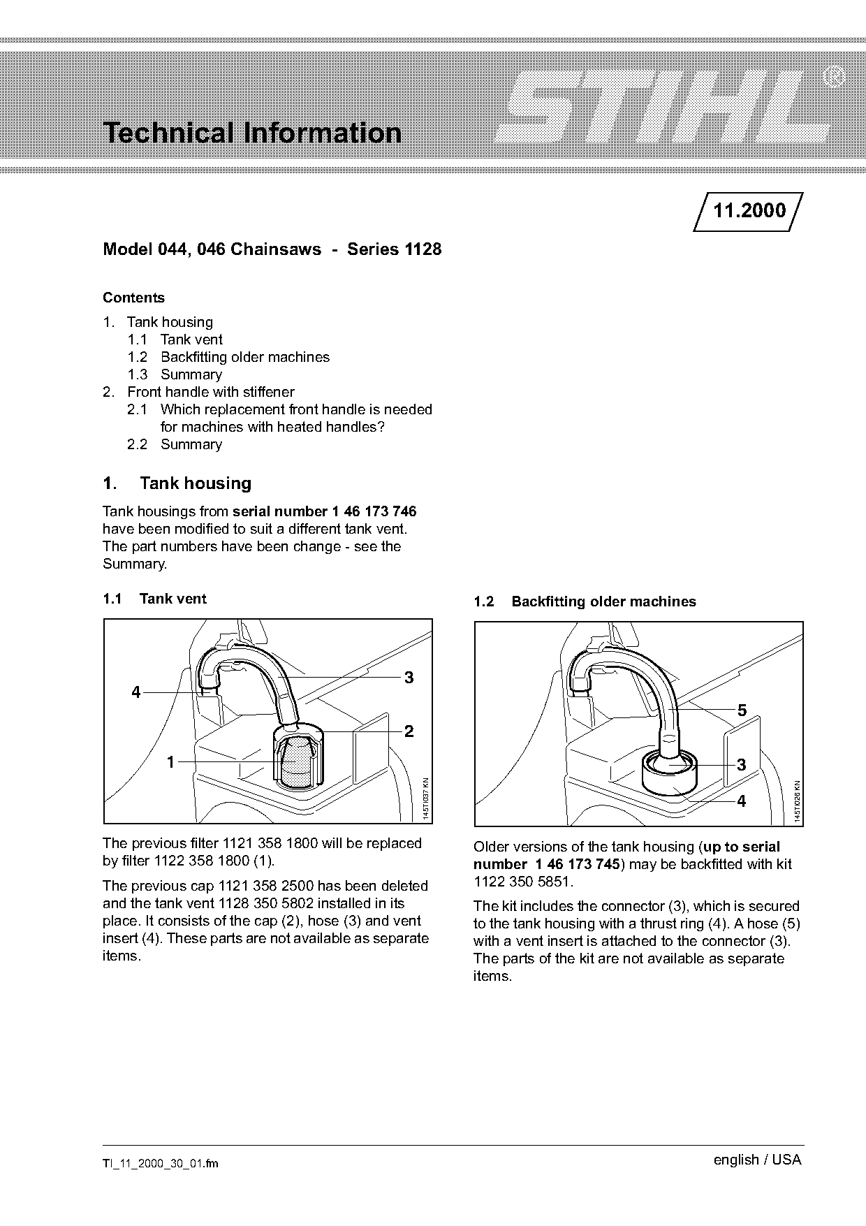
Tank housings from serial number 1 46 173 746
have been modified to suit a different tank vent.
The part numbers have been change - see the
Summary.

1.1   Tank vent                                                    1.2   Backfitting older machines

                                                3
      4
                                                                                                              5
                                                2
           1                                                                                                  3
                                                     145TI037 KN

                                                                                                                        145TI026 KN
                                                                                                              4

The previous filter 1121 358 1800 will be replaced                 Older versions of the tank housing (up to serial
by filter 1122 358 1800 (1).                                       number 1 46 173 745) may be backfitted with kit
The previous cap 1121 358 2500 has been deleted                    1122 350 5851.
and the tank vent 1128 350 5802 installed in its                   The kit includes the connector (3), which is secured
place. It consists of the cap (2), hose (3) and vent               to the tank housing with a thrust ring (4). A hose (5)
insert (4). These parts are not available as separate              with a vent insert is attached to the connector (3).
items.                                                             The parts of the kit are not available as separate
                                                                   items.

TI_11_2000_30_01.fm                                                                                       english / USA
Page 2 of 5
Text of page 2 — search, copy, screen readers
Page 2                                                                                 Technical Information 11.2000

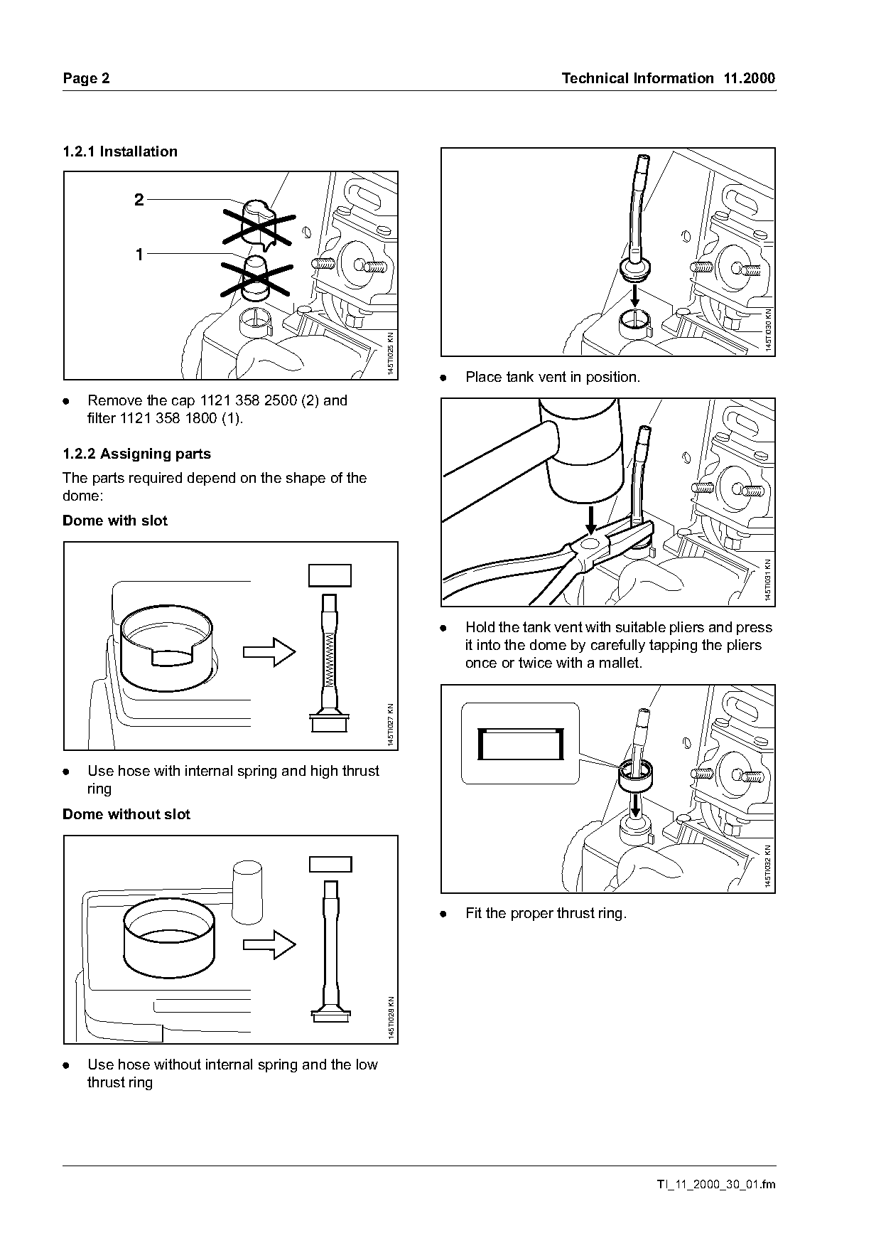
1.2.1 Installation


                                                                                                                        145TI030 KN
                                                    145TI025 KN
                                                                   .   Place tank vent in position.
.   Remove the cap 1121 358 2500 (2) and
    filter 1121 358 1800 (1).

1.2.2 Assigning parts
The parts required depend on the shape of the
dome:
Dome with slot

                                                                                                                       145TI031 KN
                                                                   .   Hold the tank vent with suitable pliers and press
                                                                       it into the dome by carefully tapping the pliers
                                                                       once or twice with a mallet.
                                                    145TI027 KN

.   Use hose with internal spring and high thrust
    ring
Dome without slot
                                                                                                                       145TI032 KN

                                                                   .   Fit the proper thrust ring.
                                                     145TI028 KN

.   Use hose without internal spring and the low
    thrust ring

                                                                                                      TI_11_2000_30_01.fm
Page 3 of 5
Text of page 3 — search, copy, screen readers
Technical Information 11.2000                                                                          Page 3

                                                         145TI033 KN
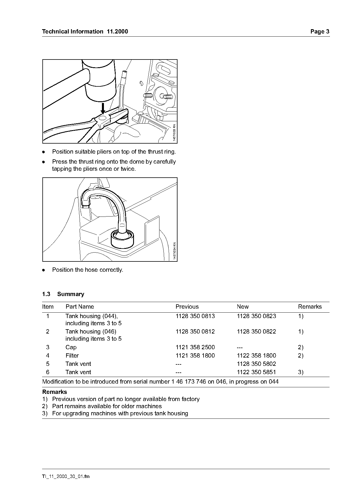
.       Position suitable pliers on top of the thrust ring.
.       Press the thrust ring onto the dome by carefully
        tapping the pliers once or twice.
                                                          145TI034 KN

.       Position the hose correctly.

1.3       Summary

Item         Part Name                                            Previous        New             Remarks
    1        Tank housing (044),                                  1128 350 0813   1128 350 0823   1)
             including items 3 to 5
    2        Tank housing (046)                                   1128 350 0812   1128 350 0822   1)
             including items 3 to 5
    3        Cap                                                  1121 358 2500   ---             2)
    4        Filter                                               1121 358 1800   1122 358 1800   2)
    5        Tank vent                                            ---             1128 350 5802
    6        Tank vent                                            ---             1122 350 5851   3)
Modification to be introduced from serial number 1 46 173 746 on 046, in progress on 044
Remarks
1) Previous version of part no longer available from factory
2) Part remains available for older machines
3) For upgrading machines with previous tank housing

TI_11_2000_30_01.fm
Page 4 of 5
Text of page 4 — search, copy, screen readers
Page 4                                                                           Technical Information 11.2000

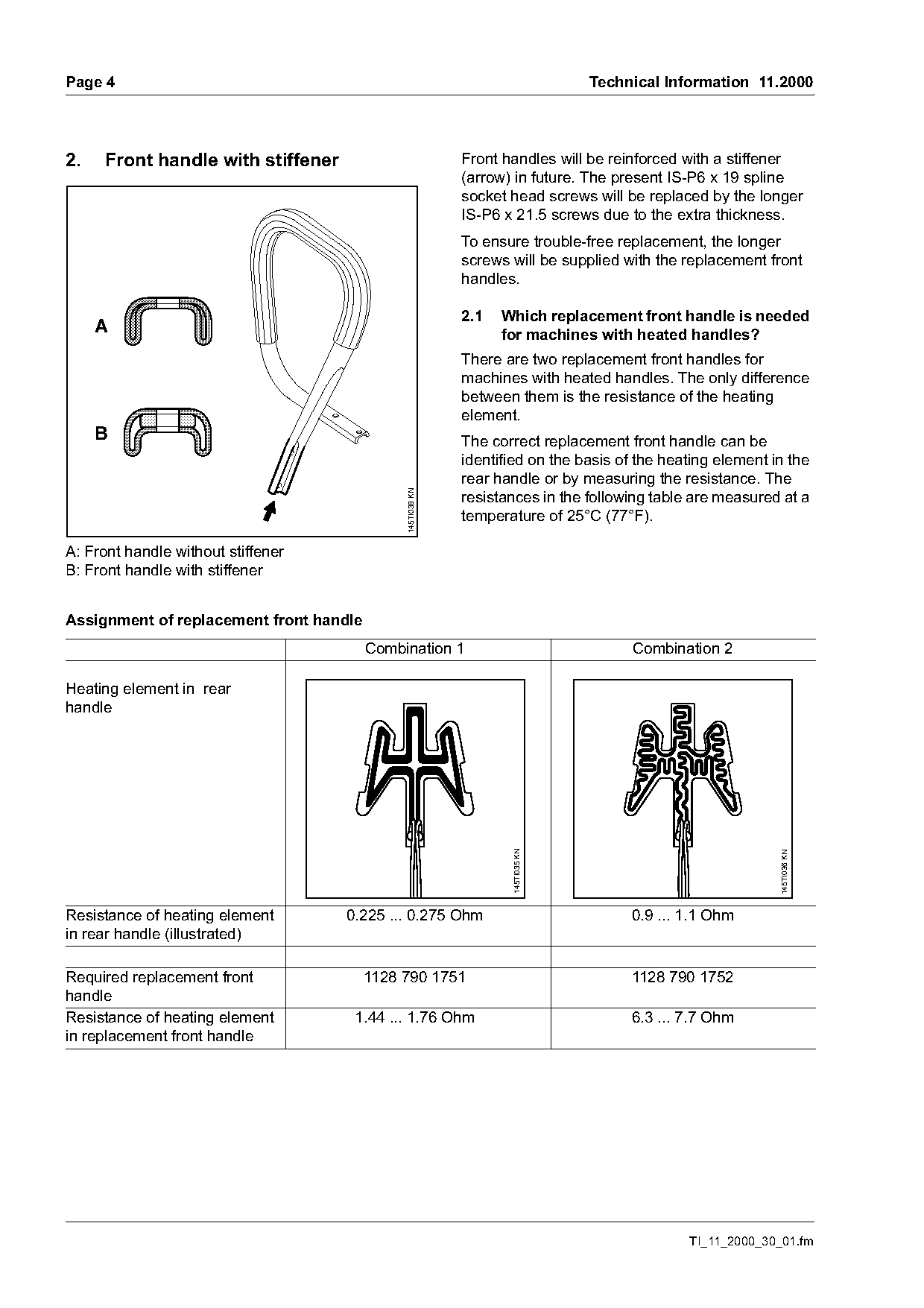
2.   Front handle with stiffener                            Front handles will be reinforced with a stiffener
                                                            (arrow) in future. The present IS-P6 x 19 spline
                                                            socket head screws will be replaced by the longer
                                                            IS-P6 x 21.5 screws due to the extra thickness.
                                                            To ensure trouble-free replacement, the longer
                                                            screws will be supplied with the replacement front
                                                            handles.

                                                            2.1   Which replacement front handle is needed
     A                                                            for machines with heated handles?
                                                            There are two replacement front handles for
                                                            machines with heated handles. The only difference
                                                            between them is the resistance of the heating
                                                            element.
     B                                                      The correct replacement front handle can be
                                                            identified on the basis of the heating element in the
                                                            rear handle or by measuring the resistance. The
                                              145TI038 KN

                                                            resistances in the following table are measured at a
                                                            temperature of 25°C (77°F).

A: Front handle without stiffener
B: Front handle with stiffener

Assignment of replacement front handle
                                         Combination 1                                Combination 2

Heating element in rear
handle
                                                                   145TI035 KN

                                                                                                            145TI036 KN

Resistance of heating element       0.225 ... 0.275 Ohm                               0.9 ... 1.1 Ohm
in rear handle (illustrated)

Required replacement front               1128 790 1751                                1128 790 1752
handle
Resistance of heating element        1.44 ... 1.76 Ohm                                6.3 ... 7.7 Ohm
in replacement front handle

                                                                                              TI_11_2000_30_01.fm
Page 5 of 5
Text of page 5 — search, copy, screen readers
Technical Information 11.2000                                                               Page 5

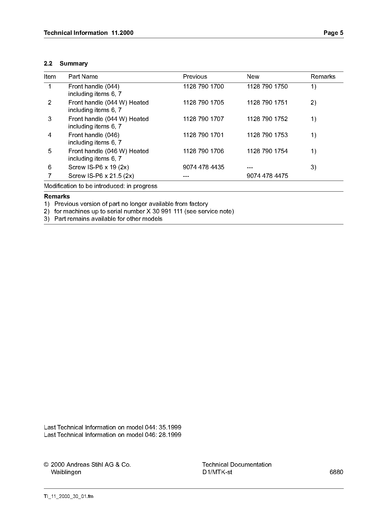
2.2    Summary

Item     Part Name                                 Previous            New             Remarks
 1       Front handle (044)                        1128 790 1700       1128 790 1750   1)
         including items 6, 7
 2       Front handle (044 W) Heated               1128 790 1705       1128 790 1751   2)
         including items 6, 7
 3       Front handle (044 W) Heated               1128 790 1707       1128 790 1752   1)
         including items 6, 7
 4       Front handle (046)                        1128 790 1701       1128 790 1753   1)
         including items 6, 7
 5       Front handle (046 W) Heated               1128 790 1706       1128 790 1754   1)
         including items 6, 7
 6       Screw IS-P6 x 19 (2x)                     9074 478 4435       ---             3)
 7       Screw IS-P6 x 21.5 (2x)                   ---                 9074 478 4475
Modification to be introduced: in progress
Remarks
1) Previous version of part no longer available from factory
2) for machines up to serial number X 30 991 111 (see service note)
3) Part remains available for other models

Last Technical Information on model 044: 35.1999
Last Technical Information on model 046: 28.1999

© 2000 Andreas Stihl AG & Co.                            Technical Documentation
  Waiblingen                                             D1/MTK-st                           6880

TI_11_2000_30_01.fm
Most of these PDFs embed fonts with a shifted character map, so the text above was recovered rather than copied — read it as a faithful but imperfect transcription, and treat the page image above each block as the authority where the two disagree — the figures exist only there, because they are vector drawings that text extraction cannot keep.